Table of Contents
Advertisement
Quick Links
Advertisement
Table of Contents

Related Manuals for Minka-Aire CONTRACTOR


Summary of Contents for Minka-Aire CONTRACTOR
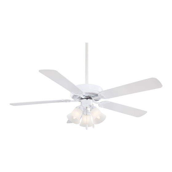
- Page 1 CONTRACTOR INSTRUCTION MANUAL WARRANTY CERTIFICATE...
- Page 2 Manual design and all elements of manual design are protected by U.S. Federal and/or State Law, including Patent, Trademark and/or Copyright laws.
- Page 3 (excluding wall controls and electrical components), to the original purchaser or user. * The warranty is voided with the use of any non- Minka-Aire®electrical devices, E.g., wall controls or electrical dimmer switches, etc… * The warranty is void once the original purchaser or user ceases to own the fan or the fan is moved from its original point of installation.
- Page 4 To obtain warranty service during the warranty period, the purchaser should return the fan with the sales receipt to the original place of purchase. The authorized Minka-Aire® dealer, at its sole discretion, will either repair or replace the fan after verifying the legitimacy of the warranty claim.
-
Page 5: Table Of Contents
CONTENTS SAFETY RULES..................ATTACHING THE FAN BLADES............PACKAGE CONTENTS..............LIGHT KIT INSTALLATION ..............INSTALLING THE FAN..............OPERATING YOUR FAN................. HANGING THE FAN................. CARE OF YOUR FAN................ELECTRICAL CONNECTIONS............TROUBLESHOOTING................FINISHING THE INSTALLATION..........SPECIFICATIONS..................1151 W. Bradford Court, Corona, CA 92882 For Customer Assistance Call: 1-800-307-3267... -
Page 6: Safety Rules
SAFETY RULES 1. Before you begin installing the fan, shut power off at the circuit breaker of the fuse box. 2. Be cautious! Be cautious! Read all instructions and safety information before installing your new fan. Review accompanying assembly diagrams. 3. - Page 7 ATTENTION: ATTENTION: The Energy Policy Act of 2005 requires this fan to be equipped with a 190 watt limiting device. If lamping exceeds 190 watts, the ceiling fan's light kit will shut off automatically. NOTE: NOTE: The important safeguards and instructions appearing in this manual are not meant to cover all possible conditions and situations that may occur.
-
Page 8: Package Contents
PACKAGE CONTENTS Unpack your fan and check the contents. You should have the following items: A. Mounting hardware: 1. Fan blades (5) #10 x 1.5" Wood screws (2 PCs.) 2. Hanger bracket #8 x 3/4" Machine screws (2 PCs.) Lock washers (2 PCs.) 3. -
Page 9: Installing The Fan
To hang your fan where there is an existing fixture but no ceiling joist, you may need to install FACING BRACKET OUTLET BOX UPSIDE ® FIG. 3 FIG. 4 a hanger bar as shown in Fig. 4 (available at your Minka-Aire dealer). -
Page 10: Hanging The Fan
HANGING THE FAN WARNING: WARNING: All of the parts, hardware and components such as the Step 3. Remove the Hanger Ball from the Downrod Assembly by loosening hanger bracket and hanger ball have been provided for your safety and the Set Screw and removing the Cross Pin. (Fig. 7) the proper installation of your new ceiling fan. - Page 11 DOWNROD OUTLET BOX CROSS PIN DOWNROD CANOPY SET SCREWS LOCK PIN HITCH HANGER SET SCREW REGISTRATION SUPPLY SET SCREWS BALL SLOT WIRES DOWNROD HANGER BRACKET Fig. 5 Fig. 6 Fig. 7 Fig. 8 Fig. 10 HITCH PIN LOCK PIN Fig. 9...
-
Page 12: Electrical Connections
(Fig. 11) Step 3. Figure 12 & 13 Illustrate the wiring connections using optional wall ® unit. (Available at your Minka-Aire Retailer.) NOTE: NOTE: If a light kit is not included with your fan, one can be purchased at your Fig. - Page 13 FAN CONTROLLED BY PULL CHAIN, LIGHT KIT CONTROLLED BY WALL SWITCH. FAN CONTROLLED BY WALL CONTROL, LIGHT KIT CONTROLLED BY LIGHT SWITCH. HOUSE WIRE SUPPLY HOUSE WIRE SUPPLY WHITE (NEUTRAL) GREEN (GROUND) WHITE (NEUTRAL) GREEN (GROUND) BLACK (HOT) BLACK (HOT) CEILING CEILING LIGHT SWITCH...
-
Page 14: Finishing The Installation
FINISHING THE INSTALLATION Outlet Box Hanger Step 1. Remove 1 of the 2 screws from the bottom of the hanger bracket and loosen the other one Bracket half a turn from the screw head. Screw Step 2. Slide the canopy up towards the hanger bracket and place the key hole on the canopy over the screw on the hanger bracket, turn canopy until it locks in place at the narrow section of the key holes. -
Page 15: Attaching The Fan Blades
ATTACHING THE FAN BLADES Step 1. Attach the fan blades to the blade holders using the screws and fiber washers provided, tighten screws securely. (Fig. 15) SCREWS Step 2. Remove rubber stops from motor. Align FIBER WASHERS motor holes to blade holders and secure with screws provided, tighten screws securely. -
Page 16: Light Kit Installation
LIGHT KIT INSTALLATION REMEMBER: REMEMBER: To disconnect the power. The fan blades must be already attached to the fan. ATTENTION: ATTENTION: The Energy Policy Act of 2005 requires this fan to be equipped with a 190 watt limiting device. If lamping exceeds 190 watts, the ceiling fan's light kit will shut off automatically. Step 1. - Page 17 Step 2. Mount the glass shades to the light kit by unscrewing partway the thumb screws on the glass holders, inserting the glass, then gently tightening the thumb screws by hand evenly to the glass. DO NOT OVER TIGHTEN. DO NOT OVER TIGHTEN. (Fig. 18) Repeat process with other glass shades. Step 3.
-
Page 18: Operating Your Fan
OPERATING YOUR FAN Restore power to ceiling fan and test for proper operation. Speed settings for warm or cool weather depend on factors such as the room size. Ceiling height, number of fans, etc. The Reverse switch is located on the switch cup. Slide the switch to the Down for warm weather operation. Slide the switch to the Up for cool weather operation. - Page 19 WINTER OPERATION SUMMER OPERATION Fig. 19 Fig. 20...
-
Page 20: Care Of Your Fan
CARE OF YOUR FAN Here are some suggestions to help maintain your fan. 4. Use a lint free lightly damp cloth or duster to remove dust from the blades. 1. Because of the fan's natural movement some connections may become loose. Check the support connections, brackets and blade 5. -
Page 21: Troubleshooting
TROUBLESHOOTING SYMPTOM SYMPTOM Fan will not start Fan Sounds Noisy SOLUTION SOLUTION Check fuses or circuit breakers. Allow a 24-hour "break-in" period. Most noises as sociated with a new fan go away during this time. Check line wire connections to fan and switch wire connections in switch housing. - Page 22 SYMPTOM SYMPTOM Fan Wobble Lights shut off and will not come back on. SOLUTION SOLUTION Check that all blade and blade holder screws are secured. This unit is equipped with a wattage limiting device. Lamping in excess of 190 watts will disable your ceiling fan’s light kit. To reset your light If a Balancing kit is provided follow the instructions included with kit you must turn the power off and re lamp, keeping the wattage the balancing kit to help correct any excessive wobble.
-
Page 23: Specifications
SPECIFICATIONS These are typical readings. Your actual fan may vary. Fan Size Speed Volts Amps Watts N.W. G.W. C.F. They do not include amps and wattage used by the 0.20 1300 light(s). 52" 7.18 8.17 1.565' Medium 0.36 2800 High 0.54 4800 For any additional information about your...
Need help?
Do you have a question about the CONTRACTOR and is the answer not in the manual?
Questions and answers