Vivotek ND8401 User Manual
Network video recorder
Hide thumbs
Also See for ND8401:
- Installation manual (12 pages) ,
- Quick installation manual (11 pages) ,
- User manual (9 pages)

Subscribe to Our Youtube Channel
Related Manuals for Vivotek ND8401


Summary of Contents for Vivotek ND8401
- Page 1 VIVOTEK ND8401 Network Video Recorder User’s Manual VAST inside • HD Local Display • Full Integration with VIVOTEK Cameras Rev. 1.6.1.11 Rev. 1.0 Rev. 1.2 User's Manual - 1...
-
Page 2: Table Of Contents
VIVOTEK Table of Contents Revision History ..............................7 Chapter One Hardware Installation and Initial Configuration ..................9 Introducing ND8401 Network Video Recorder ....................... 9 Special Features ............................. 9 Physical Description ............................10 Hardware Installation ............................11 Network Deployment ............................14 Initial Configuration ............................... - Page 3 VIVOTEK Dual / Multiple Streams .......................... 52 Fisheye Display Modes .......................... 52 Refresh ..............................57 Streaming Server ........................... 57 Get Public IP ............................57 Camera Settings ............................ 58 Remove Live Video from the Video Monitoring Window ................58 How to Change the VAST LiveClient Layout ......................59 Changing the Layout of the Live Video Monitoring Window ................
- Page 4 VIVOTEK Edit Camera List ............................91 Edit Time Frame List ............................. 92 Add New Time Frames ........................... 93 Recording Settings ..........................94 The Concept of Repeat Frequency ....................... 95 Repeat Frequency: Daily Setting ......................96 Repeat Frequency: Weekly Setting (Day-based) ................... 99 Repeat Frequency: Monthly Setting (Day-based) ................
- Page 5 VIVOTEK General Settings ............................134 System Settings ........................... 134 Event Settings ............................135 Rotation Settings ..........................135 Display Settings ........................... 136 Joystick Settings ............................138 Enable Joystick ............................ 138 Proxy Settings ............................. 142 How to Use PiP (Picture-in-Picture) ........................143 Enable PiP ..............................
- Page 6 VIVOTEK Event Category- All Events ........................172 Event Category- All Motion Events....................... 172 Event Category- All IVA events ......................173 Event Category- All DI Events ......................173 Event Category- Named DI Events ...................... 174 Start Event Search ............................175 Backup the Event Videos ..........................176 How to Search for a Bookmark ..........................
-
Page 7: Revision History
Network Camera and ensure proper operations. For creative and professional developers, the URL Commands of the Network Camera section serves as a helpful reference to customizing existing homepages or integrating with the current web server. Package Contents ■ ND8401 ■ Power cord ■ Software CD ■ Warranty Card ■... - Page 8 VIVOTEK NOTE: The operating system and VAST server are installed on an IDE flash mounted on the main board. There is no need to install software. Symbols and Statements in this Document INFORMATION: provides important messages or advices that might help prevent inconvenient or problem situations.
-
Page 9: Chapter One Hardware Installation And Initial Configuration
ND8401 the easiest NVR to use yet. When connecting ND8401 to more than one of the same model of VI- VOTEK camera, the “Shepherd” program can be used to duplicate the configuration to multiple cameras. -
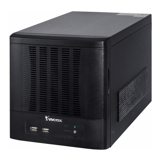
Page 10: Physical Description
VIVOTEK Physical Description Disk 1 Front View Disk 2 Disk 3 Disk 4 HDD LED Power button & LED Reset button USB ports Rear View Fan exhaust outlet Power Switch Power Socket LAN - WAN RS-232 (reserved) Line In Line Out... -
Page 11: Hardware Installation
VIVOTEK IMPORTANT: For a RAID volume configuration, it is recommended you use hard drives of the same model featuring the same capacity and rotation speed, even running the same version of firmware. Hardware Installation SATA hard disk(s) are user-supplied. The network video recorder can readily accommodate most of the off-the-shelf SATA hard drives. - Page 12 VIVOTEK IMPORTANT: Avoid touching the hard drive's circuit board or connector pins. Doing so can damage the hard drive by electro-static discharge. 5. Install drive tray by pushing it into drive bay. when it is almost fully inserted, close the bezel.
- Page 13 VIVOTEK Interface Connections 1 & 2. Connect CAT5 or better-quality Ethernet cables to cameras via a local, switched net- work, or clients through the Internet. Refer to next page for more information. 3. Connect the DB15 VGA port to a monitor (with resolutions up to 1920x1080).
-
Page 14: Network Deployment
VIVOTEK Network Deployment 1. Connect network cameras to the NVR’s LAN ports. 2. If you want to access NVR over the Internet, connect the NVR to the Internet via the WAN port. A web console can be established from a remote PC by keying http://<public IP>:3454 in a browser’s URL address field. -
Page 15: Initial Configuration
VIVOTEK Initial Configuration 1. The system power on self test and OS initialization takes about 2 minutes to complete. Once your NVR is started, you will be prompted by the Setup Wizard. You should then begin the initial setup. The system is booted from an embedded IDE flash. No software installation is required. - Page 16 VIVOTEK 4-3. Connect your WAN port to a router or AP with the routing capability and then to a DSL or Cable modem. 16 - User's Manual...
- Page 17 VIVOTEK 5. On the Disk page, Select disk drives by clicking the checkboxes in front of disk drives.Select Build single disk, Build RAID0, RAID1, RAID5, RAID10 or other option from the Disk configuration pull-down menu. Click Apply and wait for a few minutes for the configuration to take effect.
-
Page 18: Ready To Use
VIVOTEK Ready to Use 1. You will then be at the Control Center screen. Double-click on the LiveClient or Playback buttons to configure live viewing and recording settings. 2. Open the LiveClient utility to change live view layout, camera streaming frame rate, and other options. - Page 19 VIVOTEK 3-2. Click on the Search button. 3-3. Select cameras by clicking their checkboxes. 3-4. Click OK, return to the previous window, and click the Insert button. 4. It is important to ensure that the live viewing and recording configuration does not...
- Page 20 VIVOTEK In terms of local display, the default stream 1 for live view can be configured with a Make resolution up to Full HD 30fps. Stream 1 is also a source for continuous recording. sure your cameras' stream 1 resolution does not exceed 1080P at 30fps.
-
Page 21: Nvr Desktop Elements
Import/ Export The Import/ Export utility helps preserve current system configuration or reload a previously-saved configuration. Installation The IW2 utility offers a glimpse of VIVOTEK cameras and the access to them Wizard 2 in a local area network. Shepherd You can use Shepherd to quickly duplicate individual camera configuration (system, video streams, network, security, etc.) to multiple cameras. -
Page 22: Menu Bar
VIVOTEK Upgrade The Upgrade provides access to NVR system updates. File Manager The File Manager helps locate particular system or video data when the need arises, say, for retrieving forensic evidences. Keyboard If a keyboard is not available, use this virtual keyboard for entering data. -
Page 23: Chapter Two Nvr Liveclient Configuration
VIVOTEK Chapter Two NVR LiveClient Configuration Centralized management site for all the logged in clients An NVR can also be managed using a separately-installed LiveClient on a remote PC (rev. 1.7.x or later). Local 1080P HD display ... -
Page 24: Vast Liveclient Functionality
VIVOTEK VAST LiveClient Functionality Server function control User account management Recording storage management Recording schedule management Recorded data backup and automated schedule Event trigger management Flexible video live view layout A screen for a maximum of 8 channels for simultaneous monitoring ... -
Page 25: Vast Server
VIVOTEK VAST Server Activating the VAST Server VAST Server is a service program that will run automatically when your NVR system starts. The VAST server manages video recording, live view monitoring, and other related surveillance functions. How to Stop/Reboot the Server Please follow the steps below to stop/reboot the server: 1. -
Page 26: Liveclient Configuration
VIVOTEK LiveClient Configuration Opening the LiveClient Interface and Logging in VAST LiveClient allows you to monitor live video from cameras managed by the NVR; it is also the main access to the server's functional control. Double-click on the LiveClient shortcut on the desktop to open the LiveClient utility: 1. -
Page 27: Liveclient User Interface
VIVOTEK LiveClient User Interface A. Menu bar B. Quick access bar C. Hierarchical management tree D. Camera control panel (PTZ / Two way audio / Instant Playback control panel) E. Live view window F. Status panel G. Event window Menu Bar... -
Page 28: Quick Access Bar
Some buttons will be disabled if the selected devices do not support the related functions. Live Video Monitoring Window The "VIVOTEK" logo is displayed where no camera has been assigned to a video cell. The red frame ( ) represents the current selection. -
Page 29: Hierarchical Management Tree
Layout list Icon Description A station (The NVR running the VAST Server) VIVOTEK fixed network camera Red dot signifies that the camera is recording. VIVOTEK PTZ network camera Red dot signifies that the camera is recording. VIVOTEK dome network camera Red dot signifies that the camera is recording. -
Page 30: Camera Control Panel
PTZ option(s) will appear on the drop-down list. For detailed camera control settings, please refer to the user's manual of VIVOTEK network camera . Click System > Enable Click On Image to use the mouse for the control of the PTZ and e-PTZ functions in the ... -
Page 31: Two Way Audio Control Panel
VIVOTEK Two Way Audio Control Panel The two way audio function allows the user to remotely communicate with people nearby the network camera. Selected device that can use the two way audio function Click to play sound from the camera... -
Page 32: Event Window
VIVOTEK Event Window Click View > Event Window to insert a window showing the real-time information for event triggers. If you want to hide this window, deselect this option on the menu bar. Event Window The default event window is fixed on the bottom of the LiveClient. -
Page 33: Instant Playback (On Remote Liveclient)
VIVOTEK Instant Playback (on Remote LiveClient) Instant Playback is available on a remote LiveClient console. Check View > Instant Playback to open the window on the panel. The entries are the short recordings made from triggered events. Uncheck this item if you want to hide this window. - Page 34 VIVOTEK Prerequisites for Instant Replay: 1. The function is enabled by default, only available on a LiveClient installed on a PC. 2. There must be recorded videos of the immediate past. If the video streams from a camera were not recorded, you can not retrieve videos using the Instant Replay function.
-
Page 35: Audio Control
VIVOTEK To change the default Replay settings, open the Configuration > Client Settings > General Settings menu. Audio Control The audio function will be enabled if the device is equipped with an internal or external microphone. For detailed audio control settings, please refer to page 138. -
Page 36: How To Manage Devices (Cameras)
Connection Settings. If the camera is on the LAN, you can click Search Camera to detect all VIVOTEK network cameras on the LAN. A Camera List window will pop up and show a list of detected cameras on the LAN. - Page 37 VIVOTEK 2010/12/10 17:08:56 NOTE: If you want to use "HTTPS Port", please enable the HTTPs settings on the configuration page of a web console with a Network Camera. Refer to the camera's User Manual for details. The characteristics of each protocol are shown in the following table: ...
- Page 38 > Audio and Video to activate "Time Shift Cache Stream" on the camera and select a stream source. This will help record complete pre-event recording. Note that some of VIVOTEK's latest cameras have this function enabled by default. No configuration option is needed on the camera.
- Page 39 VIVOTEK 2010/12/10 17:08:56 f. The device will automatically be assigned to the default Storage Group. Deselect the item if you want to cancel this setting. g. When all settings are completed, click Insert to add the device to the station. The device will be displayed under the Camera List on the left.
-
Page 40: Enable Svc
VIVOTEK Enable SVC If the camera to-be-added supports the latest SVC (Scalable Video Coding) feature, select the SVC checkbox to enable the related control. The SVC feature enables streaming of videos for multiple clients from one single set of layered IP packets. Designed for saving bandwidth and CPU load on client stations, the frame rate of a video stream appearing through a view cell can be individually adjusted. - Page 41 Maximum Minimum NOTE: The SVC feature only applies to video streams using VIVOTEK's proprietary SVC compression format. It is not applicable to MPEG-4 streams. Please refer to Configuration -> Media -> Video for individaul stream settings. User's Manual - 41...
- Page 42 VIVOTEK If you have multiple SVC-enabled cameras, you can enable a collective setting via the Adjust SVC level button on the tool bar. The frame rate selected here will then apply to all view cells on the VAST LiveClient console.
-
Page 43: Update Devices
VIVOTEK Update Devices Please follow the steps below to update a device via Camera Management window: a. Click Configuration > Camera Management > Update Camera on the menu bar (or right-click the device/station, then select Camera Management > Update Camera). -
Page 44: Delete Devices From The Station
VIVOTEK Delete Devices from the Station Delete a device: Right-click the device on the device tree, then select Delete. A dialog box will pop up. Click Yes to delete the device along with the recorded data; click No to delete the device but retain the recorded data;... -
Page 45: Batch Insert Cameras
VIVOTEK Batch Insert Cameras Batch insert is a very useful function that allows user to search, filter, and import a row of devices that are in the same LAN to an NVR station. Basic settings can also be applied to those inserted devices simultaneously. - Page 46 VIVOTEK IP with prefix: Key in in the prefix of the IP address to narrow down the list. Model with prefix: The user can type in the prefix of the model name or the complete model name of ...
- Page 47 VIVOTEK e. When the list is filtered, you can select the cameras one by one or check Select All to add them to the batch insert list. Then click OK to finish searching. f. The selected cameras will be shown on the batch insert camera list with the camera information and the connection status.
- Page 48 VIVOTEK g. At the bottom of the window, there is a field for you to alter the camera settings including Connection Settings and Recording Settings. You can apply the new settings to each camera on the list, or click Apply to All to apply the same configurations to all the cameras. For more information about Connection Settings and Recording Settings, please refer to Insert Device on page 36 for detailed information.
-
Page 49: Camera Configuration
VIVOTEK Camera Configuration The Camera Configuration function group provides immediate access to the video streaming and other settings without the need to open a web console. The function group is accessed by selecting a camera on the device tree, and right-click to select Camera Management > Camera Configuration. - Page 50 VIVOTEK Video This tabbed window privides access to the selection of the live view stream, its compression codec, frame size, max. frame rate, and video quality. Note that the Constant Bit Rate methodology can be used to ensure that the size of video stream does not exceed a preferred threshold, regardless of the complexity or the changes of pixels in the image.
- Page 51 VIVOTEK Remote Focus For cameras supporting the remote focus feature, such as the FD8362E that comes with a motorized lens, this window provides finetune buttons and full-range scan fucntion to help reach the best image fo- cus. NTP Settings ...
-
Page 52: View Live Videos
VIVOTEK View Live Videos You should double-click on the target device or drag-and-drop the target device from the hierarchical management tree window to a video cell. Mega-Pixel Network Camera Dual / Multiple Streams For multiple-stream devices, you can right-click on the focused view cell to select a stream. The NVR system automatically selects a video stream depending on the size of the current layout and view window. - Page 53 VIVOTEK Fisheye Display Modes: below are conceptual drawings for different display modes. (Single Original) Display mode: (Single Regional) Display mode: An Original oval view covers the A Regional view crops a portion of the hemisphere hemisphere taken by the fisheye as a region of interest.
- Page 54 VIVOTEK (2 Panoramic) Display mode: Two dewarped rectangular views are placed one on top of another each showing 180 degree of panoramic view. The 2P view looks like the upper view shows the front of hemisphere, and the lower view the rear half of the hemisphere.
- Page 55 VIVOTEK PTZ Mouse Control The "Mount type" setting also determines the display modes available to your fisheye cameras. Please refer to fisheye camera's User Manual for more information. A highly versatile mouse control is implemented with fisheye cameras. The same control takes effect on a browser management session, on the LiveClient utility, and even on a video playback screen.
- Page 56 VIVOTEK Below are the conceptual drawings for other display modes: 1P3R (One Panoramic & 3 Regional) Display mode: Panoramic View Regional View #1 Regional View #2 Regional View #3 (Quad Regional) Display mode: 4RPro (4 Regional Proactive) Display mode: Regional View #2...
-
Page 57: Refresh
VIVOTEK NOTE: For Fisheye video playback and recording concerns, refer to page 131 and page 167. Refresh Right-click the device, then click Refresh, the camera information will be refreshed from the server. Streaming Server Right-click the station or the device and click Output Streaming URL. A .txt file with streaming URL will pop up. -
Page 58: Camera Settings
VIVOTEK Camera Settings Right-click the device, then click Camera Settings to open a brower's session to the camera. Remove Live Video from the Video Monitoring Window There are two ways to remove a live video from the video cell: Method 1. Right-click the video cell and select Remove. -
Page 59: How To Change The Vast Liveclient Layout
VIVOTEK How to Change the VAST LiveClient Layout Changing the Layout of the Live Video Monitoring Window The NVR's LiveClient supports up to 16 simultaneous video viewing on a single monitor and allows you to change the layout of the live video monitoring window based on the number of inserted devices. -
Page 60: Rotating Video Pages
VIVOTEK For example, under the 3 x 3 layout mode, you can switch among the pages by clicking the quick access bar. To arrange the content of each page, manually drag-and-drop cameras from the hierarchical device tree to the video cells on each page. - Page 61 VIVOTEK d. Back to the monitoring window, the new layout will appear under the device tree as shown below. You can save up to 10 layouts. e. To change to another layout, double-click the layout options on the hierarchical management tree, or click Layout >...
-
Page 62: Maximize The Live Video Monitoring Window
VIVOTEK Maximize the Live Video Monitoring Window Single View: to maxmize a video cell to the entire live video window Double-click the video cell, or right-click the video cell and select Single View. The focused video will occupy the entire playback window as shown below. - Page 63 VIVOTEK Full Screen: Maximize the live video monitoring window to the entire screen Click Full Screen on the quick access bar or right-click the video cell and select Full Screen. In addition, you can also click View > Full Screen on the menu bar to maximize the live video monitoring window.
-
Page 64: How To Manage Stations
VIVOTEK How to Manage Stations A standard VAST Server allows you to construct a hierarchical management system by adding more sub-stations to the root station. The NVR system can be included into a hierarchy managed by a dominating VAST server. The NVR system itself can not manage other sub- stations. -
Page 65: How To Manage User Accounts
VIVOTEK How to Manage User Accounts VAST on NVR allows users to apply multiple user accounts to a station with five levels of user roles: Administrator > Power User > User > Operator > Guest. Each role has different permissions listed as shown below. Moreover, Administrators have the highest privileges, while Power Users can only add/edit users as Power Users, Users, Operators, and Guests. - Page 66 VIVOTEK Privileges \ User Roles Administrator Power User User Operator Guest Description Add, remove and rename Modify Directories directories Delete camera from the Delete Camera station PTZ control for PTZ PTZ Control cameras and speed domes in LiveClient Control the digital output or...
-
Page 67: Manage A User Account
VIVOTEK Manage a User Account Add a New User Account a. Select the station from the hierarchical management tree. b. Click Configuration > User Management on the menu bar (or right-click the station, then select User Management). c. The User Management window will pop up. The user accounts under the station will be displayed under the left User List tree. -
Page 68: Permission Of The User Account
VIVOTEK Permission of the User Account Administrator is granted with all access privileges, while other user roles' permission is limited. If you want to modify the permission, please login as the Administrator to configure the settings. f. Select a User account from the User List tree. -
Page 69: Delete The User Account
VIVOTEK NOTE: If you want to remove access permission mentioned above from the account, the user will not be able to operate some functions listed in the following warning dialog. j. When completed, click Update to enable the new settings. -
Page 70: How To Set Up Association Management
VIVOTEK How to Set up Association Management The LiveClient supports association management which allows the user to configure relative event trigger notifications of the connected network devices. (E.g., DI/DO status on the management tree, motion detection windows appearing in the video cell, or the event list in the... - Page 71 VIVOTEK NOTE: To manually enable DI/DO settings, please right-click the video cell and select Set DO to enable (Trigger) or disable (Normal) the digital output of the linked device. Before you configure the DI/DO Settings for VAST, please enable DI/DO configurations on your network device ...
-
Page 72: How To Set Up Event Management
(events). LiveClient can correspond with cameras' input and respond with associated reactions, such as sending notifications, telling cameras to move to preset locations, etc. Record on local VIVOTEK Network Cameras Camera Status, Motion, Move to preset DI/DO, Video loss, locations Tampering, PIR, Temperature... -
Page 73: Event Management
VIVOTEK Event Management Please follow the steps below to configure event management: a. Select the station from the hierarchical management tree. b. Click Configuration > Event Management on the menu bar (or right-click the station and select Event Management). c. The Event Management window will pop up. Click New to set up a new event. When you finish the general settings, click Next to set up trigger source settings. - Page 74 VIVOTEK e. The Device List window will prompt. Select one or more devices and set the Notification Type. Depending on the trigger source, the Notification Type will be different. Then click OK to close the window. f. The trigger source(s) will be listed on the window as shown below.
- Page 75 VIVOTEK Start to record on: The sever will start to record video from selected camera(s) when an event is triggered. j. Click Add Camera to select the target camera(s). k. The selected camera(s) will be listed on the left window below. When completed, click OK at the bottom to enable the setting.
- Page 76 VIVOTEK GSM Short Message: The sever will send a short message to a GSM cell phone when an event is triggered. A GSM modem is necessary. q. Please enter the Phone Number and open GSM Settings window to set related information if necessary.
- Page 77 VIVOTEK Client Notification: This function allows a notification video cell to prompt when an event is triggered. You can select the size of the video cell, and select how long the view cell will stay on top of the screen.
- Page 78 VIVOTEK t. When you finish schedule settings, click Next to review the detailed information of the new event settings. 78 - User's Manual...
- Page 79 VIVOTEK u. Following is the detailed information of the new event setting. You can click Back to modify the event setting or click Finish to close the window. v. Following is an example of an enabled event. You can click New to set up more events or click Close to exit the window.
-
Page 80: How To Configure The Station General Settings
VIVOTEK How to Configure the Station General Settings Select the target station from the hierarchical management tree, then click Configuration > Station Settings > General Settings on the menu bar (or right-click the station on the hierarchical management tree and select Station Settings > General Settings). The Station General Settings window will pop up. -
Page 81: Reboot Settings
VIVOTEK Reboot Settings You can schedule a system reboot every day at a specific time in a day or in days within a week. Select the checkbox and select a time from the pull-down list. Click OK when the configuration is done. -
Page 82: How To Configure Station Network Settings
VIVOTEK How to Configure Station Network Settings Select the target station from the hierarchical management tree, then click Configuration > Station Settings > Network Settings on the menu bar (or right-click the station on the hierarchical management tree and select Station Settings > Network Settings). The Network Settings window will pop up. -
Page 83: How To Edit Recording Stoage
VIVOTEK How to Edit Recording Stoage By default, all devices (cameras) are assigned to the default recording storage. You can manually remove a device from the default recording storage. However, only those devices which belong to a recording storage can produce recorded media files. -
Page 84: Default Storage Group Settings
VIVOTEK Default Storage Group Settings The following example shows the default storage group settings. You can click Rename to modify the group name or click Delete to remove the default settings. d. The default recording path is E:\Recording. The total space and free space of the disk is shown on the right for reference. - Page 85 VIVOTEK e. Add Local Path: Click to add another recording path on your local computer. A Select Path dialog will pop up as shown below. When all settings are complete, click OK to enable the settings, or click Cancel to discard the settings.
- Page 86 VIVOTEK g. To modify the settings of a path, select the path from the list, then click Change settings to modify. h. To delete a path, select the path from the list and click Delete path. A warning dialog box will pop up as shown below.
-
Page 87: Add New Storage Group(S)
VIVOTEK Add New Storage Group(s) If you want to add a new storage group, click Add to give a name to the new storage group, which will be displayed on the drop-down list. The following is an example of storage group list. -
Page 88: How To Edit Recording Schedules
VIVOTEK How to Edit Recording Schedules After editing recording storage settings, you can begin to edit recording schedules for the devices in a storage group. By default, all devices are assigned to the default recording schedule (Please refer to the default time frame settings on page 92). Therefore, once you insert a device to the station, the VAST Server will begin to record live video according to the default recording schedule. -
Page 89: Edit Schedule List
VIVOTEK Edit Schedule List Please follow the steps below to set up the recording schedules: a. Select the VAST station from the hierarchical device tree. b. Click Configuration > Station Settings > Recording Schedule Settings on the menu bar (or right- click the station and select Station Settings >... -
Page 90: Load/Save Schedule Templates
VIVOTEK Load/Save Schedule Templates g. If you have a schedule template with time frame settings, you can upload it to facilitate the scheduling process. Click Load Template, and a Load File dialog box will pop up. Select the template file and click Open to load. -
Page 91: Edit Camera List
VIVOTEK Edit Camera List Please follow the steps below to assign a device to a recording schedule: a. Select a recording schedule on the schedule drop-down list. b. By default, all devices under the station are assigned to the Default Schedule. -
Page 92: Edit Time Frame List
VIVOTEK Edit Time Frame List Default Time Frame: Weekly (Day-based), Mon.~Sun., 24-hour, continuous recording Click Edit to open the Default Time Frame settings page as shown below. 92 - User's Manual... -
Page 93: Add New Time Frames
VIVOTEK Add New Time Frames Please follow the steps below to add new time frames to a schedule: a. Select a recording schedule from the drop-down list. b. Click Add to open the Time Frame Settings window. c. Enter a name for the new time frame. -
Page 94: Recording Settings
VIVOTEK h. If you want to add additional time frames to the schedule, repeat the steps above. i. Close the window when you finish the time frame settings. j. Back to the Recording Schedule Settings window, the new time frame will be displayed on the Time Frame List. -
Page 95: The Concept Of Repeat Frequency
VIVOTEK NOTE: The following diagrams show the frame rate variations using two different recording modes: 1. Continuous recording + Activity adaptive recording (helps save bandwidth and storage) Bandwidth Time I frame ---> Full frame rate ---> I frame Continuous Recording 2. -
Page 96: Repeat Frequency: Daily Setting
VIVOTEK Repeat Frequency: Daily Setting To set up daily repeat frequency, please configure the following items: Daily time segments, applicable period of time, and repeat time interval. Daily time segments *You can drag the daily timeline bar for more Daily timeline control bar than one time segment per day. - Page 97 VIVOTEK 2. Fill in the precise Start Time and End Time: a. Directly enter the value in the Start Time and End Time fields, then click Add. b. The corresponding red timeline bar will automatically appear as shown below. Delete time segments: Choose either step 1 or step 2 to set up 1.
- Page 98 VIVOTEK Set up applicable period of time For repeat frequencies, you can set up the applicable date and period of time for the time frame. a. Specify the start date and time in the Start field. A calendar date selector will appear when you click on the drop-down list of date.
-
Page 99: Repeat Frequency: Weekly Setting (Day-Based)
VIVOTEK Repeat Frequency: Weekly Setting (Day-based) To set up Weekly (Day-based) repeat frequency, please configure the following items: Daily time segments, applicable days within a week, applicable period of time, and repeat time interval. Daily Time segments Daily timeline control bar (24h) - Page 100 VIVOTEK Repeat Frequency: Weekly Setting (Periods in a week) To set up Weekly (Periods in a week) repeat frequency, please configure the following items: Time segments within a week, applicable period of time, and repeat time interval. Weekly timeline control bar...
- Page 101 VIVOTEK 2. Fill in a precise Start Time and End Time: a. Directly select a day and enter the value in the Start Time and End Time fields, then click Add. b. The corresponding red timeline bars will automatically appear as shown below.
-
Page 102: Repeat Frequency: Monthly Setting (Day-Based)
VIVOTEK Repeat Frequency: Monthly Setting (Day-based) To set up Monthly (Day-based) repeat frequency, please configure the following items: Daily time segments, applicable date(s) of a month/ day(s) of a week, applicable period of time, and repeat time interval. Daily time segments... - Page 103 VIVOTEK Repeat by date(s) of a month: Select date(s) from the calendar, and it will be displayed on the right blank as shown below. The following example refers to the 1 day of a month. Repeat by day(s) of a week: Select day(s) from the calendar, and it will be displayed on the right blank as shown below.
-
Page 104: Repeat Frequency: Yearly Setting (Day-Based)
VIVOTEK Repeat Frequency: Yearly Setting (Day-based) To set up Yearly (Day-based) repeat frequency, please configure the following items: Daily time segments, applicable date(s) of a year/ day(s) of a week, applicable period of time, and repeat time interval. Daily time segments... - Page 105 VIVOTEK Repeat by date(s) of a year: Select date(s) from the calendar, and it will be displayed on the right blank as shown below. The following example refers to the 1 day of a year. Repeat by day(s) of a week: Select day(s) from the calendar, and it will be displayed on the right blank as shown below.
-
Page 106: How To Manually Begin /Stop Recording
VIVOTEK How to Manually Begin /Stop Recording By default, all devices are assigned to the default recording storage and default recording schedule. Therefore, once you included a camera into the NVR's configuration, the VAST Server will begin to record live video according to the default recording schedule. Please refer to How to Edit Recording Schedules on page 88. -
Page 107: How To Edit Scheduled Backup Settings
VIVOTEK How to Edit Scheduled Backup Settings VAST LiveClient supports scheduled backup which allows the user to back up the recorded data in another disk. Please follow the steps below to enable scheduled backup settings: a. Select the target station from the device tree. -
Page 108: Setup Backup Schedule
VIVOTEK Setup Backup Schedule f. Fill in a desired time and click >> to add the backup time. Please note that the backup time interval must not be shorter than 1 hour. For example, 23:40 and 00:15 are not allowed to exist simultaneously. -
Page 109: How To Configure Station Server Settings
Select a DDNS provider from the provider drop-down list. VIVOTEK offers 2bthere.net (Safe100. net), a free dynamic domain name service, to VIVOTEK customers. Please refer to the user's manual of VIVOTEK's network camera for detailed DDNS settings. User's Manual - 109... -
Page 110: Network Storage Server Settings
VIVOTEK Network Storage Server Settings The VAST Server allows user to set up network storage path(s) for recorded files. Please follow the steps below to add a new network storage path. a. Click Add to open the Network Host Window. -
Page 111: Smtp Settings
VIVOTEK SMTP Settings VAST Server allows user to set up SMTP Server to send mail alert when event triggers. For more information about how to set up event management, please refer to page 72. Please follow the steps below to configure the SMTP Server: a. -
Page 112: How To Use The Talk Panel
VIVOTEK How to Use the Talk Panel VAST LiveClient supports the two way audio function which allows the user to communicate with people around the network camera. Please enable the two way audio function on the camera side. Below is a conceptual drawing of the two way audio function:... - Page 113 VIVOTEK An icon with the camera name will be displayed in the Talk Panel. Click to play sound from the camera Remove all cameras Click to talk from the Talk Panel Select sound from the file list Click to play the selected...
-
Page 114: Remove A Camera From The Talk Panel
VIVOTEK Remove a Camera from the Talk Panel Remove a camera Drag a camera from the Talk Panel and drop to the hierarchical management tree window as shown below. The camera icon will disappear. Remove all cameras Click , all cameras in the Talk Panel will be removed. -
Page 115: How To Configure E-Map Settings
VIVOTEK How to Configure E-map Settings VAST LiveClient supports intuitive E-map function which allows users to upload E-maps for overall devices management. Click System > E-map to open E-map Settings Page: Upload an E-map Click to search for E-map(s) to upload. -
Page 116: E-Map Settings Page (View Mode)
VIVOTEK E-map Settings Page (View Mode) Double-click an E-map on the tree, it will be displayed on the E-map window as shown below. There are two operation modes of E-map settings page: "View Mode" and "Edit Mode". The following is the "View Mode" illustration. -
Page 117: Quick Access Bar
VIVOTEK Quick Access Bar Icon Function Description Zoom in Zoom in the E-map Zoom out Zoom out the E-map Default size Adjust the E-map to default size Upload Upload E-map to the login station View Mode Click to switch to view mode... -
Page 118: E-Map Settings Page (Edit Mode)
VIVOTEK E-map Settings Page (Edit Mode) A. Menu bar B. Quick access bar C. E-map list tree D. Device tree E. Map preview F. E-map window G. Status panel Right-click the E-map, you can delete an existing E-map. 118 - User's Manual... -
Page 119: Device Management
VIVOTEK Device Management Please follow the steps below to edit an uploaded E-map. a. Double-click the E-map you want to edit, it will be displayed on the E-map window. b. Use Quick Access Bar to adjust the size of the E-map. In edit mode, you can also use your mouse to drag the position of the E-map and zoom in or zoom out the E-map. -
Page 120: Live View Dialog Settings
VIVOTEK Live View Dialog Settings Click System > E-map Settings to open the E-map Settings dialog, then you can choose to Open Live View Dialog or to Send to Single View when you double-click the device deployed on the E-map. -
Page 121: E-Map Link
VIVOTEK NOTE: The live view dialog also supports click on image, PTZ, and e-PTZ as long as the connected camera also supports and has enabled these functions. To enable those function on E-map, please check the item "Enable click on image" on the menu bar of LiveClient as shown below. Then an icon will appear in the live view dialog for you to control the cameras. - Page 122 VIVOTEK d. Right-click the blue frame to Resize or Delete it. Click Resize, some nodes will appear around the blue frame. Then You can drag the nodes to move the position, rotate the direction, adjust the size, and change the shape.
- Page 123 VIVOTEK h. Test the web links. Click on the Quick Access Bar to switch to view mode. Double-click the blue frame on Map1, it will automatically switch to map2. Then double-click the blue frame on Map2, it will automatically switch to map3.
-
Page 124: How To Configure Client Settings
VIVOTEK How to Configure Client Settings In Client Settings, you can configure Snapshot Settings, Recording Settings, View Settings, General Settings, Joystick Settings, Proxy Settings, and PiP Settings. Snapshot Settings Please follow the steps below to configure snapshot settings: a. Click Configuration > Client Settings > Snapshot Settings on the menu bar to open the Snapshot Settings window. -
Page 125: Taking A Snapshot
VIVOTEK If you uncheck Generate a file name automatically, the Save file dialog box will pop up when you take a snapshot. The file name prefix will automatically be displayed in the Save File dialog box. Taking a Snapshot Please follow the steps below to take a snapshot of the live video stream: a. -
Page 126: Recording Settings
VIVOTEK Recording Settings The VAST Server allows you to record the live video in EXE, 3GP, or AVI format to your storage folder. Type 1: Record to EXE Record video as an EXE file. The EXE is not only a media file but also a built-in media player. When user execute the EXE, the media file will be played automatically. -
Page 127: Type 3: Record To Avi
VIVOTEK d. If you check "Record with only standard codec", the video from old models (VIVOTEK 6000-series products) using H.263 codec will not be recorded. f. Click OK to enable the settings. Type 3: Record to AVI Record video as an AVI file, which uses the popular codecs pre-installed in the Windows OS. Please note that the speed may be slower due to the need of decoding the video/audio and re-encoding both into a compatible codec. - Page 128 VIVOTEK d. Select the frame rate/ per second. e. To modify the video compression settings, click Video Compression Setting to open the AVI Video Compression Setting window. Select the desired video compression algorithm, compression quality, key frame intervals, and data rate in the corresponding fields.
- Page 129 VIVOTEK Record an EXE/3GP/AVI File Please follow the steps below to record an EXE/3GP/AVI file of a live video stream: a. Select a video cell or a device from the heirarchical management tree which you want to record to media file.
-
Page 130: Built-In Media Player--Exe
Below is the icon of footages saved as EXE files. Double-click on it, the recorded video will be played automatically as shown below. If you installed LiveClient on your PC, you may also open the built-in Media Player (VMSMediaPlayer.exe) in the default location: C:\Program Files (x86)\VIVOTEK Inc\VAST\ Client\LiveClient. - Page 131 VIVOTEK The function menu of the built-in media player are displayed as shown below: The built-in player is able to playback 3GP files. The built-in player is able to save 3GP files as EXE files. The built-in player is able to save EXE files as 3GP files.
-
Page 132: View Settings
VIVOTEK View Settings This section allows you to set the display mode of a video cell, including Display Location, Date and time Format, Video Display Mode, and Font Settings. When you change the settings, the sample window will change accordingly for you to preview the settings. -
Page 133: Date And Time Format
VIVOTEK Date and Time Format Same as local computer: Select this option and then the date and time format will synchronize with the local computer. Specify: Select a desired format for the date and time from the drop-down list. -
Page 134: General Settings
VAST VAST Client Server 1 manages 2 sub-stations VAST VAST Server 2-2 Server 2-1 VIVOTEK IP Camera VIVOTEK IP Camera ST7501 VAST ST7501 ST7501 Server 3-1 Server 3-2 Server 3-3 Server 3-4... -
Page 135: Event Settings
VIVOTEK Event Settings Enable live event notification: Select this option to activate real-time event notification. For example: the event notification of DI/O status on the hierarchical management tree, the event list in the event window, motion detection windows in video window, or the event notification on E-map settings page, etc. -
Page 136: Display Settings
VIVOTEK Display Settings WARNING: Please do not disable the Auto stream size option. Disabling Auto stream size can cause a performance problem with the system. Today's megapixel cameras produce high resolution videos that, if not properly processed, can overstress the system. - Page 137 VIVOTEK Enable Instant Replay on video cell (on a LiveClient installed to a PC): When enabled, a small Replay icon will be available on each view cell. One pre-condition is that the video stream must be currenly being recorded to the NVR sysm.
-
Page 138: Joystick Settings
VIVOTEK Joystick Settings This section explains how to remotely control the network cameras using a USB joystick. Enable Joystick Connect to the USB plug of the joystick to a USB port on your computer. Supported by the plug-in in the main page (Microsoft’s DirectX), once the plug-in in the main page is loaded, it will automatically detect if... - Page 139 VIVOTEK Buttons Configuration In Button Configuration window, the left column shows the actions you can assign, and the right column shows the functional buttons and assigned actions. The number of buttons may differ from different joysticks. Please follow the steps below to configure your joystick buttons: a.
- Page 140 VIVOTEK c. The Assigned Action will appear beside Button 1 in the right column as shown in the following diagram. Note that a button can only be assigned with an action. If you want to modify the settings, select the action on the list and click Clear Selected.
- Page 141 VIVOTEK e. Click OK to save the settings or click Cancel to discard the settings. NOTE: If you want to assign Preset actions to your joystick, the preset locations should be set up in advance. If your joystick is not working properly, it may need to be calibrated. Click Calibrate to open the Game Controllers ...
-
Page 142: Proxy Settings
VIVOTEK PTZ/ E-PTZ Function In addition to using the PTZ control panel, you may also control the rotation handle on the joystick with ease. Pan/Tilt: Move the rotation handle of the joystick; you can pan the camera to the desire position. There will be blue line displaying the moving direction in the center of the video image as the diagram 1 below. -
Page 143: How To Use Pip (Picture-In-Picture)
VIVOTEK How to Use PiP (Picture-in-Picture) PiP (Picture-in-Picture) is an intuitive function for user to simultaneously view a Global View and ROI (Region of Interest) for live monitoring. The digital zoom in function can only focus on the interested area and represent the details of megapixel video. Moreover, the multi-touch mode is a very user-friendly interface for digital zoom in. -
Page 144: Roi (Region Of Interest)
VIVOTEK ROI (Region of Interest) The ROI frame can be resized and moved in any direction across the global view window. The working theory is similar to the e-PTZ function. Digital Zoom In Through digital zoom in, the live view window will be filled with the zoomed in ROI image. The maximum magnification of the ROI frame is 16x zooming. -
Page 145: How To Configure Video Enhancement
VIVOTEK How to Configure Video Enhancement IMPORTANT: The Video Enhancement function consumes considerable system resources. It is not recommended to exert this function on multiple view cells. The LiveClient allows you to enable post-image enhancement and defog for video live view. - Page 146 VIVOTEK 2013/01/08 12:20:22 g. Back to the main page, a “VE” text string will also appear at the bottom right of the video cell and the new profile will also appear and be selected on the popup menu as shown below.
-
Page 147: Defog
VIVOTEK Defog This function allows you to configure post-image defog. Apply a Preset Defog Profile Please follow the steps below to set post-image defog settings: a. Select the target video cell. b. Click Configuration > Video Enhancement > Defog or right-click the video cell and select Video Enhancement >... -
Page 148: Create A New Defog Profile
VIVOTEK d. The string of the selected profile will be selected as shown below. A “VE” text string will also appear at the bottom right of the video cell. Click to create a new profile, edit or delete a customized profile... - Page 149 VIVOTEK 2013/01/13 12:20:22 f. Adjust the values of Block Size, Strength, and Threshold. You can preview the image from the right window. A “VE (Video Enhancement)” text string will also appear at the bottom right of the preview window. Block Size: Brush diameter from thick to thin (Value 1~5)
-
Page 150: How To Search For A Device On The Hierarchical Device Tree
VIVOTEK How to Search for a Device on the Hierarchical Device Tree This function allows you to conveniently search for an inserted device, which is useful when many devices have been inserted. Please follow the steps below to find a device on the camera list: a. -
Page 151: How To Lock Liveclient For Security Concerns
VIVOTEK How to Lock LiveClient for Security Concerns If you are away from your computer, for security reasons, we suggest you lock the program. When LiveClient is locked, the user must fill in the correct password to unlock and access the program again. -
Page 152: Lauch Playback
VIVOTEK Lauch Playback Click on Launch Playback to directly open the Playback utility. Note that the LiveClient utility is still running in the background when you return to the Control Center. Second View This function is only available on a LiveClient running a PC that has 2 monitors. Clicking the button opens the second live view window enabling the display of more camera views. -
Page 153: Chapter Three Nvr Playback Configuration
VIVOTEK Chapter Three NVR Playback Configuration Activating VAST Playback and Logging in to a Server VAST Playback allows you to search and playback recorded media data from the NVR system. Once you insert a device into the hierarchical device tree on the LiveClient, it is automatically listed on the device tree on the Playback utility. - Page 154 VIVOTEK NOTE: If your network environment need to set up proxy, click More >> to extend the login window, then click Proxy Setting to open the dialog. Then enter related information to link to your proxy server. Available functions of the VAST Playback program will be enabled according to the role of your login account. For ...
-
Page 155: Vast Playback User Interface
VIVOTEK VAST Playback User Interface A. Menu bar B. Quick access bar C. Query panel (Browsing / Time search /Event search / Log viewer) D. Status panel E. Recorded video playback window F. Playback control panel G. Video clips list... -
Page 156: Quick Access Bar
Some buttons will be disabled if the selected device does not support those functions. Recorded Video Playback Window The "VIVOTEK" wallpaper is in place if no camera has been assigned to the video cell. The red frame ( ) represents the focused cell. -
Page 157: Query Panel-- Browsing Page
VIVOTEK Query Panel-- Browsing Page Root Station Name (IP address) Dates with recorded Devices listed video clips under the NVR station Local Database Synchronous Playback Click to enable synchronous playback for multiple channels Icon Description NVR Station list including server and local database A station (NVR that has a running VAST Server) The camera that exists on the hierarchical device tree of LiveClient. -
Page 158: Query Panel--Time Search Page
VIVOTEK Query Panel--Time Search Page Select station(s)/ device(s) that you want to search for recorded files Specify search period of time Click to start to search, the results will be shown on the video clips list NOTE: The Time Zone setting is automatically synchronized with that on the NVR station. -
Page 159: Audio Control
VIVOTEK Audio Control The audio function will be enabled if the device is equipped with an internal or external microphone. Please follow the steps below to adjust the volume or turn the audio on/off for a video stream: To turn off the audio (Mute Mode) ... -
Page 160: How To Change The Playback Layout
How to Change the Playback Layout Changing the Layout of the Recorded Video Playback Window VIVOTEK VAST Playback supports up to 16-CH simultaneous recorded video playback on a single monitor and allows you to change the layout of the recorded live video playback window based on the number of inserted devices. -
Page 161: Maximize The Recorded Video Playback Window
VIVOTEK Maximize the Recorded Video Playback Window Single View: to maxmize a video cell to the entire video playback window Double-click the video cell, or right-click the video cell and selec Single View. The selected video will expand to fill the entire Playback window as shown below. - Page 162 VIVOTEK Full Screen: to maxmize the video playback window to the entire screen Click Full Screen on the quick access bar or right-click the video cell and select Full Screen. In addition, you can also click View > Full Screen on the menu bar to maximize the recorded video playback window.
-
Page 163: How To Backup Recorded Video
VIVOTEK How to Backup Recorded Video In addition to the Schedule Backup function of VAST LiveClient introduced on page 61, the Playback utility can back up recorded video clips from the local database. Please open the Browsing page and follow the steps below to backup recorded video: a. - Page 164 VIVOTEK To backup part of the recorded video of the day: Select the date and choose the video clip(s) from video clip window. Then right-click the selected option(s) and click Backup. Note: Use the combination of the Shift key and left mouse click to select multiple video clips.
- Page 165 VIVOTEK How to View Backup Files The VAST Playback also allows users to playback backup files, including Schedule Backup by VAST LiveClient and Recorded Data Backup by VAST Playback. Please follow the steps below to view backup files: a. Right-click Local DB and click Add.
- Page 166 VIVOTEK NOTE: 1. The Backup function does not take place between the NVR system and a PC running the Playback utility. 2. If you want to playback the backup files from the local database, you can also click Working Offline in the Login Window without the account information.
- Page 167 VIVOTEK Model-specific Functions (FE Series Fisheye) The VAST Playback program offers model-specific functions through a right-click menu. For example, if you playback a video clip made from an FE8171V or FE8172 series fisheye camera, a right-click on the playback screen will bring up the Display mode options. You can even exert mouse control while playing a recorded video.
- Page 168 VIVOTEK To configure the SVC-related feature: 1. Right-click on the playback window of an SVC-enabled camera. Select SVC fps adjust bar. 2. A slide bar will appear above the view cell. Click and drag the slide bar. A numeric indicator will display the current selection.
-
Page 169: How To Search For A Video Clip Taken At A Specific Time
VIVOTEK How to Search for a Video Clip Taken at a Specific Time Please follow the steps below to use Time Search function: a. Open the Time Search page. b. Select the target station(s)/device(s) that you want to search for video clips. -
Page 170: How To Add A Bookmark
VIVOTEK How to Add a Bookmark Bookmark is a convenient tagging function that allow your to pinpoint and extract a 20-second video clip from out of a video recording. When you see somehting of your interest while browsing through a recorded video, 1. -
Page 171: How To Search For Events
VIVOTEK How to Search for Events The VAST Playback program offers users an intuitive event search engine for retrieving video clips from the database of recorded videos based on different search criteria such as motion, IVA, or DI events. Please follow the steps below to search for recorded events: a. -
Page 172: Select Event Category
VIVOTEK Select Event Category The following introduces the event search categories: All Events, All Motion Events, All IVA events, All DI Events, Named DI Events, PIR, Tampering, and Tamperature. You can also add or remove customized events from the list. -
Page 173: Event Category- All Iva Events
VIVOTEK Event Category- All IVA events If you select the All IVA events category, all detected IVA events will be included in the search. Cameras with embedded intelligent video content analysis are capable of detecting IVA events such as moving objects, loitering, and tamper detection. -
Page 174: Event Category- Named Di Events
VIVOTEK Event Category- Named DI Events This category allows you to select only Named DI Events--the DI device which you have renamed in the LiveClient. Please refer to Association Management on page 70 for more information about how to rename DI device. -
Page 175: Start Event Search
VIVOTEK Start Event Search After you specify all of the search criteria mentioned above, select or deselect the Display in new result list checkbox and click Search to begin event search. If Display in new result list is unchecked, all search results will be displayed on the original event list ... -
Page 176: Backup The Event Videos
VIVOTEK Backup the Event Videos Please follow the steps below to backup the evnet videos on the results list: a. Select the video clips you want to backup. You can select more than one video clip using the Shift key. -
Page 177: How To Search For A Bookmark
VIVOTEK How to Search for a Bookmark Please follow the steps below to use Bookmark Search function: a. Click on the tabbed menu to open the Bookmark Search page. b. Select the cameras which have video clips you have placed bookmarks on. -
Page 178: How To Search Logs
VIVOTEK How to Search Logs The VAST Playback program offers a convenient log engine for searching all local logs based on different search criteria such as log category, log type, and log level. The search results will be displayed in the log viewer window along with the detailed log history. -
Page 179: Select Log Category/Log Type/Log Level
VIVOTEK Select Log Category/Log Type/Log Level The following table shows the breakdown of log category, level, and type. The search results will be different according to your selections. Log Categories Log Levels Log Types Login / Logout Insert User Update User Name... -
Page 180: Search All Local Logs
VIVOTEK Log Categories Log Levels Log Types Camera Disconnected from the Server / Camera Connected to the Server Camera Recording Start / Camera Recording Stop Event Log High Start Scheduled Backup / Stop Scheduled Backup Event Trigger Search All Local Logs... -
Page 181: Search Login Activities
VIVOTEK Search Login Activities This function allows you to search the operations the user performed during the login period of time. You can search for login activities on the Local Logs or Login History page. Search Login Activities on the Local Logs page: ... - Page 182 VIVOTEK d. The search results of the login activities will be displayed on the Login Activities page as shown below. NOTE: When you select All in the Log Level field, the search results will include all log levels. If you select Low in the Log Level field and select Including above level as shown in the picture below, the search results will include all levels of logs.
-
Page 183: How To Configure Client Settings
VIVOTEK How to Configure Client Settings On Client Settings, you can configure Snapshot Settings, Export Settings, View Settings, Proxy Settings, and General Settings. It allows you to save snapshots and media files on the local computer. Snapshot Settings When you play a recorded video, VAST Playback also allows you to take snapshots. For detailed information about Snapshot Settings, please refer to page 124. - Page 184 Exporting Status. d. When the backup is complete, you will see an information dialog. The exported data will be restored in the preset storage folder on your local computer (C:\Program Files\VIVOTEK Inc\VAST\Client\ Playback\Export). Note that the local computer has a Playback instance that is separately installed. If you are running Playback on the NVR, you can backup to the local disks or USB devices.
-
Page 185: View Settings
VIVOTEK View Settings This section allows you to set up the display mode of video cell. For detailed information about View Settings, please refer to page 132. Proxy Settings Please refer to page 142 for detailed illustration. General Settings System Settings Please refer to page 134 for detailed information. -
Page 186: How To Lock Vast Playback For Security Concerns
VIVOTEK How to Lock VAST Playback for Security Concerns If you happen to be away from your computer, for security reasons, we suggest you lock the program. When VAST Playback is locked, the user must enter the correct password to unlock and access the program again. -
Page 187: Chapter Four Auxiliary Utilities
Import/ Export The Import/ Export utility helps preserve current system configuration or reload a previously-saved configuration. Installation The IW2 utility offers a glimpse of VIVOTEK cameras and the access to them Wizard 2 in a local area network. Shepherd You can use shepherd to quickly duplicate individual camera configuration (system, video streams, network, security, etc.) to multiple cameras. -
Page 188: Service
VIVOTEK Service Chances are you may need to stop and restart the embedded VAST server. On occasions such as stopping a recording task, server reported errors, or after you update the software components of the VAST server, you can manually stop and then restart the service. - Page 189 VIVOTEK To import a previously saved configuration: a. Click Import previous settings. b. Use the browse button to locate a configuration bin file. c. Click open. A message prompt will appear warning you about the replacement of current settings. The process may take several minutes to complete. Click Close to finish the process. Your system should now be in sync with the imported configuration.
-
Page 190: Installation Wizard 2
VIVOTEK Installation Wizard 2 This is the same utility that comes with every VIVOTEK's network camera. You can use it to scan the local network for all VIVOTEK's network camers, NVR systems, and video servers. Please refer to cameras' software CD for its operation manual. -
Page 191: Shepherd
Unfold menu items and select the items you wish to duplicate to other cameras. e. Click Export. A Paramters ini file will be created into the D:\VIVOTEK Inc\Shepherd folder. f. Click to open the Import tabbed menu. Use the Browse button to open the Parameters file. - Page 192 VIVOTEK i. A warning message will remind you of the IP address. If you configured a static IP on the source camera, it is recommended to change it to the automatic IP address setting. j. A progress bar will appear on the screen.
-
Page 193: Upgrade
Upgrade Software upgrade packages will be released on VIVOTEK's support website. You can download these files, and double-click the Upgrade shortcut to open the utility. Please consult VIVOTEK's technical support and the release note before applying upgrades. Locate the upgrade package and click open. The upgrade process should be completed within minutes. -
Page 194: File Manager
VIVOTEK File Manager The File Manager provides access to the file browser window of the embedded operating system. By default, the recorded video files should be recorded to the E: volume, and you can use the Export EXE and other similar functions in the Playback utility to extract video clips to the E: volume. -
Page 195: Disk Status
VIVOTEK Disk Status Click on the tabbed menu on the desktop to enter the Disk Status window. The first information is the Logical volume working status. The second window displays the working status of individual disk drives, including model name, capacity, S.M.A.R.T., state, and temperature. Note that if a hard drive is stated as an ArrayMember, the physical drive has already been included into a logical, multi-drive configuration such as RAID0 or RAID1. -
Page 196: Network Status
VIVOTEK You may perform Quick Test or Complete Test to acquire the current integrity status. The test utility then polls the hard drives for statuses of the key attributes of its working conditions. The Quick test checks the electrical and mechanical performance as well as the read performance of the disk. -
Page 197: System Status
VIVOTEK System Status System Status states the current working status and system time. User's Manual - 197... -
Page 198: Appendix A Rebuilding A Raid Volume
VIVOTEK Appendix A Rebuilding a RAID Volume If a drive fails, the failure will be indicated by the system fault LED or the Disk Status panel. If a disk drive fails in a RAID5 volume, first locate the faulty drive in the Disk Status panel, remove the faulty drive with a drive of the same capacity and rotation speed. - Page 199 VIVOTEK Once you replace the faulty drive with a new one, an automatic rebuild will begin, and its progress will be indicated by a status bar as shown below. The process will take hours depending on the sizes of your disk drives, e.g., 8 hours if using 2TB drives in a RAID5 volume.
-
Page 200: Appendix B Onvif Support
VIVOTEK Appendix B ONVIF Support Prerequisites: 1. You may connect cameras made by other manufacturers to the system as long as their firmware supports the ONVIF. You may upgrade their firmware if the newer firmware supports ONVIF. 2. The supported ONVIF revision is 2.2. - Page 201 VIVOTEK 6. Visual indication on user interface: A camera on the device tree A camera recording to the system On the insert camera window, an ONVIF brand option is added. User's Manual - 201...
-
Page 202: Technical Specifications
ND8401, AUN 100091110G ND8401, Mexico 100091200G ND8401, EU 100091120G All speci cations are subject to change without notice. Copyright © VIVOTEK INC. All rights reserved. Distributed by: Ver 1.3 VIVOTEK INC. VIVOTEK USA VIVOTEK Europe 6F, No.192, Lien-Cheng Rd., Chung-Ho,...
Need help?
Do you have a question about the ND8401 and is the answer not in the manual?
Questions and answers