Vivotek ND8401 Installation Manual
Vast inside hd local display full integration with vivotek cameras
Hide thumbs
Also See for ND8401:
- User manual (202 pages) ,
- Quick installation manual (11 pages) ,
- Specification (2 pages)
Table of Contents
Advertisement
Quick Links
Download this manual
See also:
User Manual
Advertisement
Table of Contents

Related Manuals for Vivotek ND8401


Summary of Contents for Vivotek ND8401
- Page 1 ND8401 Network Video Recorder Quick Installation Guide Русский Česky Svenska Nederlands 繁中 簡中 日本語 Türkçe English Français Español Deutsch Português Italiano Polski Indonesia Dansk...
-
Page 2: Package Contents
Do not attempt to remove or uninstall the software on the mounted IDE flash. Nor should you open the chassis. Doing so will void our warranty. Package Contents ND8401 Power Cord Software CD Quick Installation Guide Screws and Bezel Keys... -
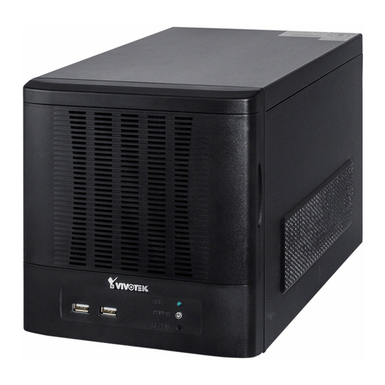
Page 3: Physical Description
Physical Description Front View Disk 1 Disk 2 Disk 3 Disk 4 HDD LED Power button & LED Rear View Reset button USB ports Fan exhaust outlet Power Switch Power Socket LAN - WAN RS-232 (reserved) Line In Line Out MIC In USB combo eSATA IMPORTANT:... -
Page 4: Hardware Installation
Hardware Installation SATA hard disk(s) are user-supplied. The network video recorder can readily accommodate most of the off-the-shelf SATA hard drives. 1. Open the front panel. 2. Use the included bezel key to unlock the bezel lock. 3. Open the drive tray bezel by flipping the bezel latch to the side. The bezel lever will spring open, and you can then remove the drive tray. - Page 5 IMPORTANT: Avoid touching the hard drive's circuit board or connector pins. Doing so can damage the hard drive by electro-static discharge. 5. Install drive tray by pushing it into drive bay. When it is almost fully inserted, close the bezel. The bezel will secure the back-end connection to the backplane. Bezel Lever 6.
- Page 6 Interface Connections 1 & 2. Connect CAT5 or better-quality Ethernet cables to cameras via a local, switched network, or clients through the Internet. Refer to next page for more information. 3. Connect the DB15 VGA port to a monitor (with resolutions up to 1920x1080). 4.
-
Page 7: Network Deployment
Network Deployment 1. Connect network cameras to the NVR’s LAN ports. 2. If you want to access NVR over the Internet, connect the NVR to the Internet via the WAN port. A web console can be established from a remote PC by keying http://<public IP>:3454 in a browser’s URL address field. -
Page 8: Initial Configuration
Initial Configuration 1. Once your NVR is started, you will be prompted by the Setup Wizard. You should then begin the initial setup. The system is booted from an embedded IDE flash. No software installation is required. NOTE: You must install at least one hard drive for the initial configuration. -
Page 9: Ready To Use
6. On the Camera page, all cameras connected through the local network should appear on a Camera list after a brief search. You can manually assign IP addresses by clicking on the cameras' address field. You can also select the "Assign IP addresses to all cameras" checkbox and let NVR assign IPs to cameras. - Page 10 3. 3-1. By default, the Batch Insert Cameras window will prompt for you to recruit cameras into your configuration. 3-3. Select cameras by clicking their checkboxes. 3-4. Click OK, return to the previous window, and click the Insert button. 3-2. Click on the Search button. 4.
- Page 11 P/N:625020401G Rev. 1.1 All specifications are subject to change without notice. Copyright 2013 VIVOTEK INC. All rights reserved. VIVOTEK INC. VIVOTEK USA, INC. 6F, No.192, Lien-Cheng Rd., Chung-Ho, New Taipei City, 235, Taiwan, R.O.C. 2050 Ringwood Avenue, San Jose, CA 95131 |T: +886-2-82455282| F: +886-2-82455532| E: sales@vivotek.com...
Need help?
Do you have a question about the ND8401 and is the answer not in the manual?
Questions and answers