2N NetStar Hardware Manual
Digital communication system
Hide thumbs
Also See for NetStar:
- Manual (282 pages) ,
- Assistant manual (91 pages) ,
- User manual (60 pages)
Table of Contents
Advertisement
Quick Links
Advertisement
Table of Contents

Related Manuals for 2N NetStar


Summary of Contents for 2N NetStar
- Page 1 ® NetStar Communication System Hardware manual Version 4.3.x www.2n.cz ...
- Page 2 Declaration of Conformity see the CD-ROM (if enclosed) or our website at www.2n.cz. The 2N TELEKOMUNIKACE a.s. is the holder of the ISO 9001:2009 certificate. All development, production and distribution processes of the company are managed by this standard and guarantee a high quality, technical level and professional aspect of all our products.
-
Page 3: Table Of Contents
Content 1. System Installation ....... . . 4 1.1 Select of the Installation part . . . . . . . . . . . . . . . . . . . . . . . . . . . . . . . . . . . . . . . 6 ... -
Page 4: System Installation
CAT 3 or CAT 5 patch panel. If the infrastructure is already ready the switchboard installation site is usually given and can not be further changes. The interface must however be adjusted for the connection via RJ 45 8/8 plugs. ® TELEKOMUNIKACE a.s., www.2n.cz... - Page 5 Caution In the areas with very poor GSM signal level or high number of GSM gates the use of internal (takes the position of a line card) or external GSM splitter is advantageous. ® TELEKOMUNIKACE a.s., www.2n.cz...
-
Page 6: Select Of The Installation Part
Note In the areas with very poor GSM signal level or high number of GSM gates the use of internal (takes the position of a line card) or external GSM splitter is advantageous. ® TELEKOMUNIKACE a.s., www.2n.cz... -
Page 7: Unwrapping And Control
The installation set, electronic documentation on a CD and warranty certificate are a part of the delivery. The remaining components such as telephone units and other terminals or additional appliances are delivered separately. ® TELEKOMUNIKACE a.s., www.2n.cz... -
Page 8: Installation
1.3 Installation Here is what you can find in this section: System Connection System Installation ® TELEKOMUNIKACE a.s., www.2n.cz... -
Page 9: System Connection
For this purpose an organizer, which at the same time will ensure a better manipulation with the wiring, can be used. For a shelf installation the system is equipped with 4 stands that create a gap between the shelf and the module body to ensure sufficient system ventilation. ® TELEKOMUNIKACE a.s., www.2n.cz... - Page 10 If you do not use the additional system grounding, the over voltage protection integrated in the line cards will not work. ® Netstar communication system was designed as digital appliance (TDM circle switching) with sufficiently powerful processor and LAN connection with integrated VoIP telephony. ® TELEKOMUNIKACE a.s., www.2n.cz...
-
Page 11: Terms And Symbols
Useful information for quick and efficient functionality. Note Routines or advice for efficient use of the device. Future Functions, Innovations grey-marked text in this document designates the functions that are under preparation or development at present. ® TELEKOMUNIKACE a.s., www.2n.cz... -
Page 12: Technical Specifications
2.5 CPU Card - Extension module 2.6 SWITCH card 2.7 PRI Card 2.8 BRI Card 2.9 DVL Card 2.10 DIGITAL COMBO Card 2.11 4ASL/4AVL Card 2.12 AVL Card 2.13 GSM Card 2.14 UMTS card 2.15 Audio Card_IO_Relay 2.16 IP Card ® TELEKOMUNIKACE a.s., www.2n.cz... -
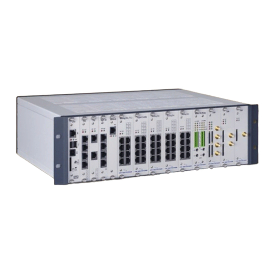
Page 13: Basic Module
2.1 Basic Module Here is what you can find in this section: Basic Module Basic Module Pro ® TELEKOMUNIKACE a.s., www.2n.cz... - Page 14 The Basic Module Lite represents a business alternative of the basic module equipped with an CPU card, Switch X card that does not enable the connection of extension modules and one AVL card. Ord. no. 101034 2N NETSTAR BASIC rack basic module 8x AVL Ord. no. 101014 2N NETSTAR BASIC module 8x ASL ®...
- Page 15 Basic Module Profi is a business alternative of the basic module equipped with a CPU card, Switch card that enables the connection of up to 4 extension modules. Ord. no. 101031 2N NETSTAR PRO rack basic module (empty) Ord. no. 101011 2N NETSTAR PRO basic module (empty) ®...
-
Page 16: Extension Module
The extension module is equipped with an 8-bit CPU, which controls up to 11 analogue line cards. The following cards are supported: AVL, ASL, GSM and AUDIORELE. Ord. no. 101036 2N NETSTAR PRO rack extender analogue only Ord. no. 101016 2N NETSTAR PRO extender analogue only ®... -
Page 17: Position And Port Numbering
The card ports are assigned the addresses from left to the right and from top to the bottom. The addresses start with 1. For the purpose of better orientation the PRI, GSM and Audio/IO/Relay cards have the serial numbers of the ports printed on their front side. ® TELEKOMUNIKACE a.s., www.2n.cz... -
Page 18: Cpu Card
The card is an inseparable part of the basic module. It contains all necessary interfaces needed for the communication with the system. It is only installed in the basic module, always in the position with the 0 HW address. ® TELEKOMUNIKACE a.s., www.2n.cz... - Page 19 MMC 4.0 and MMC Plus 13 pins Buses – 1–bit (MMC) and 4–bit (MMC4.0 and MMC+) Power supply – 3,3V Reading speed – up to 22, Mb/s Writing speed – up to 18 Mb/s Maximum recommended capacity – 4 GB ® TELEKOMUNIKACE a.s., www.2n.cz...
- Page 20 After the switching into the ON position, the card drivers are launched and their power supply is switched on – no need for the re-launching of the entire system and starting of all processes. ® TELEKOMUNIKACE a.s., www.2n.cz...
-
Page 21: Cpu Card - Extension Module
CPU card is 160 cm (wiring supplied as a part of the extender package) Total interface throughput between SWITCH card and extension module CPU card is available 31 channels (and 1 for signaling) total extension module throughput is 88 calls ® TELEKOMUNIKACE a.s., www.2n.cz... -
Page 22: Switch Card
It is only used in the basic module and is always installed in the position with 5 as the HW address. The set-up of the Jumpers on the board determines the NT or TE port type NT port set-up For NT port the pins 1–3, 2–4, 5–7, 6–8 should be connected ® TELEKOMUNIKACE a.s., www.2n.cz... - Page 23 Total interface capacity – 124 calls Ratio capacity of the interface – 4x 31 calls Maximum capacity per 1 extender 88 calls 1x PRI interface Interface type – S0 without power supply / NT–TE Protocol – DSS1 – EURO ISDN ® TELEKOMUNIKACE a.s., www.2n.cz...
- Page 24 PRI = on PRI = on PRI = on PRI = Position 4 0,1,2,3 Switch The card ports are marked blue, the Switch buses are marked red. The CPU card and the SWITCH card are filled 1:1. ® TELEKOMUNIKACE a.s., www.2n.cz...
- Page 25 If more than 3 ports are occupied on the card or cards in the positions 2, 3 and 4, the PRI cards must be equipped with another ZARLING connection field. This ensures that the call channels of all ports are connected to the basic connection field of the SWITCH card. ® TELEKOMUNIKACE a.s., www.2n.cz...
-
Page 26: Pri Card
The card is installed into the position 1, 2 and 3 of the basic module, in between the CPU and SWITCH cards. The set-up of the Jumpers on the board determines the NT or TE port type NT port set-up For NT port the pins 1–3, 2–4, 5–7, 6–8 should be connected ® TELEKOMUNIKACE a.s., www.2n.cz... - Page 27 Protocol – DSS1 – EURO ISDN Connection – RJ45 with LED control lamp TE modus Pin1, Pin2 = reception couple Pin4, Pin5 = broadcasting couple NT modus Pin1, Pin2 = broadcasting couple Pin4, Pin5 = reception couple ® TELEKOMUNIKACE a.s., www.2n.cz...
- Page 28 LED control lamp – port not allowed by the licence NO LIGHT – port allowed by the licence, the line is not connected GREEN – communication interface connected to the 2nd layer ® TELEKOMUNIKACE a.s., www.2n.cz...
-
Page 29: Bri Card
The NS Admin programming tool uses these port settings during the HW activation.. The set-up of the Jumpers on the board determines the NT or TE port type Pins 1–2, 3–4, 5–6, 7–8 and power supply pins to be connected ® TELEKOMUNIKACE a.s., www.2n.cz... - Page 30 Connect pins 1–3, 2–4, 5–7, 6–8 and do not connect the power supply pins Attention: On the positions with the HW addresses 5, 9 and 13 the ports 0 and 1 always have the NT configuration. ® TELEKOMUNIKACE a.s., www.2n.cz...
- Page 31 *Protocol * – DSS1 – EURO ISDN Connection RJ45 TE modus Pin3, Pin6 = reception couple Pin4, Pin5 = broadcasting couple NT modus Pin3, Pin6 = broadcasting couple Pin4, Pin5 = reception couple Obj. no. 1011118 2N NETSTAR module 8x BRI ® TELEKOMUNIKACE a.s., www.2n.cz...
-
Page 32: Dvl Card
After the technical deficiency was repaired, the power supply source will start to feed power into the ports again. The card is only installed into the position of the line card of the basic module. ® TELEKOMUNIKACE a.s., www.2n.cz... - Page 33 8x DVL port Interface type Upn (NT–U), LAP–S with power supply 48V Protocol Cornet II Connection RJ45 Pin4, Pin5 broadcasting/ reception Obj. no. 1011128 2N NETSTAR module 8x DVL ® TELEKOMUNIKACE a.s., www.2n.cz...
-
Page 34: Digital Combo Card
The card is installed into the line card position of the basic module. The set-up of the Jumpers on the board determines the NT or TE port type Pins 1–2, 3–4, 5–6, 7–8 and power supply pins to be connected ® TELEKOMUNIKACE a.s., www.2n.cz... - Page 35 S0 (TE–S/T, LT–S ) without power supply Protocol – DSS1 – EURO ISDN Connection – RJ45 – four conductors Pin3, Pin6 = broadcasting couple Pin4, Pin5 = reception couple Obj. no. 1011124 2N NETSTAR module 4x BRI/4x DVL ® TELEKOMUNIKACE a.s., www.2n.cz...
-
Page 36: 4Asl/4Avl Card
1999/5/ES Directive to the AVL ports. The card can be installed into any line position of the basic or the extension modules. ® TELEKOMUNIKACE a.s., www.2n.cz... - Page 37 Interface type – analogue with power supply –60V Signalisation – reverse polarity, CLIP broadcasting – FSK, DTMF Connection – RJ45 – two–wire Pin4, Pin5 = a/b wires Obj. no. 1011224 2N NETSTAR module 4xCO / 4x ASL ® TELEKOMUNIKACE a.s., www.2n.cz...
-
Page 38: Avl Card
Support of status signalisation, for pulse signalisation a constant polarity reverse is generated. The card is installed into any line position of the basic or the extension modules. Obj. no. 1011218 2N NETSTAR module 8x ASL ® TELEKOMUNIKACE a.s., www.2n.cz... - Page 39 8x ASL port Interface type – U analogue with power supply – 60V Signalisation – reverse polarity, CLIP broadcasting – FSK, DTMF Connection – RJ45 – two–wire Pin4 = GND, 0V Pin5 = –60V ® TELEKOMUNIKACE a.s., www.2n.cz...
-
Page 40: Gsm Card
1x SIM for 1 GSM module is supported The card is installed into any line position of the basic or the extension modules. GSM module Module type – SIEMENS TC35i, SIEMENS MC39 SIM card type – SIM small 3V ® TELEKOMUNIKACE a.s., www.2n.cz... -
Page 41: Umts Card
1x SIM for 1 UMTS module is supported The card is installed into any line position of the basic or the extension modules. UMTS module Module type – SIERRA WIRELESS MC8795V SIM card type – SIM small 3V ® TELEKOMUNIKACE a.s., www.2n.cz... -
Page 42: Audio Card_Io_Relay
Pin1 (middle ring) = Right channel Pin2 (front ring) = Left channel Input resistance: 160–380 kOhm (type 270kOhm) Input voltage range: max + -2,223V AC Output resistance: type 0.25Ohm Output voltage range: max + -2,223V AC ® TELEKOMUNIKACE a.s., www.2n.cz... - Page 43 ® TELEKOMUNIKACE a.s., www.2n.cz...
- Page 44 ® TELEKOMUNIKACE a.s., www.2n.cz...
- Page 45 ® TELEKOMUNIKACE a.s., www.2n.cz...
-
Page 46: Ip Card
The VoIP card can be supplies in several HW configurations. 4, 8, 16, 24 or 32 voice channels. (IEEE 802.3) Ethernet 10/100 FullDuplex The card is installed into the position 1, 2 and 3 of the basic module, in between the CPU and SWITCH cards. ® TELEKOMUNIKACE a.s., www.2n.cz... -
Page 47: Power Source
Such maintenance works may only be executed while the system is not connected to the power supply network!!! Here is what you can find in this section: 3.1 Power Supply Connection 3.2 System Grouping 3.3 Power supply backup ® TELEKOMUNIKACE a.s., www.2n.cz... -
Page 48: Power Supply Connection
If necessary, the cable may easily be disconnected from the switch–board. In case of the switch–board installation outside the 19" rack the power supply cable may be conducted to a power outlet either freely or through a cable ledge. ® TELEKOMUNIKACE a.s., www.2n.cz... -
Page 49: System Grouping
The conductor should be attached to the system using the earthed connector (on the backside of the system panel, marked with the grounding symbol) that is to be fixed properly. The grounding should be connected prior to the connection of any other wiring!!! ® TELEKOMUNIKACE a.s., www.2n.cz... - Page 50 1500 mm. The ends of the conductor are equipped with a 4 mm diameter eyelet, one end of the basic module conductor has an 8 mm diameter eyelet. Grounding conductor of the extension unit Grounding conductor of the basic unit ® TELEKOMUNIKACE a.s., www.2n.cz...
-
Page 51: Power Supply Backup
UPS – 1600W / 2200VA Number of cases Backup time 240 min 150 min 100 min 70 min 50 min NSVL8 , NSCOVL FXS – MINIMUM SERIAL RESISTOR <= 20 Table 1: NSVL8 , NSCOVL – FXS ® TELEKOMUNIKACE a.s., www.2n.cz... - Page 52 COVL – 7320F3 SL PACKAGE Table 2: CO – FXO ® TELEKOMUNIKACE a.s., www.2n.cz...
- Page 53 Table 3: COVL – FXO Itsp=max I ® TELEKOMUNIKACE a.s., www.2n.cz...
- Page 54 ® TELEKOMUNIKACE a.s., www.2n.cz...
-
Page 55: Technical Parameters
Signály: USB -A Transmission speed: 1,5 Mb/s Interface type: 2xUSB v1.1 R232 Signals: Pin1= TxD-, Pin2= TxD+, Pin3aPin4= GND, Pin5= RxD+, Pin6= RxD- Transmission speed: 115200 Bd Interface type: RS 232C / 115200Bd,8bit ,parity=none, stop bit=1 ® TELEKOMUNIKACE a.s., www.2n.cz... -
Page 56: Isdn Bri
ISDN BRI S0 TE: Interface type – S0 (TE–S/T, LT–S ) – for connection to VTS Protocol: DSS1 EURO ISDN with power supply Interface configuration: P–MP (point – several points) – supports MSN, P–P (point – point) – supports DDI Connection: 4-wires Connection type: RJ 45 ® TELEKOMUNIKACE a.s., www.2n.cz... -
Page 57: Isdn Pri
Specifications of the pulse selection reception: Pulse duration: 30 ms to 70ms Interruption duration: 30 ms to 70ms FLASH detection FLASH broadcasting specifications: 100 ms FLASH reception specifications: 80 ms...150 ms (Preset values, can not be changed) ® TELEKOMUNIKACE a.s., www.2n.cz... - Page 58 The product may only be used in compliance with the User's Manual and for purposes, for which the product was designed and manufactured. After the product lifetime was terminated please dispose the product or its parts in compliance with the valid environmental protection regulations. ® TELEKOMUNIKACE a.s., www.2n.cz...
- Page 59 2N TELEKOMUNIKACE a.s. Modřanská 621, 143 01 Prague 4, Czech Republic Phone: +420 261 301 500, Fax: +420 261 301 599 E-mail: sales@2n.cz Web: www.2n.cz ® TELEKOMUNIKACE a.s., www.2n.cz...
Need help?
Do you have a question about the NetStar and is the answer not in the manual?
Questions and answers