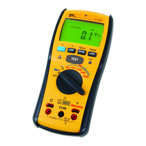
IDEAL 61-797 Manual
Digital multimeter
Hide thumbs
Also See for 61-797:
- Instruction manual (56 pages) ,
- Manual (2 pages) ,
- Instruction manual (30 pages)
Table of Contents
Advertisement
Advertisement
Table of Contents

Subscribe to Our Youtube Channel
Related Manuals for IDEAL 61-797


Summary of Contents for IDEAL 61-797
- Page 1 #61-797 Digital Multimeter - 1 -...
-
Page 2: Table Of Contents
TABLE OF CONTENTS 1.Introduction Precautions and Safety Information Symbols Safety 2.Specifications General Specifications Electrical Specifications Required Equipment 3.Basic Maintenance Battery and Fuse Replacement 4. Performance Tests 5. Calibration Procedure - 2 -... - Page 3 1. Introduction Warning To avoid shock or injury, do not perform the verification tests or calibration procedures described in the manual unless you are qualified to do so. The information provided in this document is for the use of qualified personnel only. Caution The meter contain parts that can be damaged by static discharge.
-
Page 4: Safety
SAFETY Review the following safety precautions to avoid injury and prevent damage to this product or products connected to it. To avoid potential hazards, use the product only as specified. CAUTION: These statements identify conditions or practices that could result in damage to the equipment or other property. -
Page 5: Specifications
2. Specifications General Specifications Maximum voltage applied to any terminal : 600 V ac rms or dc. Display : 4000 counts. Polarity Indication : Automatic, positive implied, negative indicated. Overrange Indication : OL Batteries Life : Resistance Measurements : Tester can perform at least 2600 earth-bond resistance measurements with new alkaline batteries at room temperature. - Page 6 Accessories : Battery (installed), Test leads and user manual. Power Requirements : 1.5V x 4 IEC LR6 or AA size. Pollution degree : 2 EMC : EN 61326-1 Shock vibration : Sinusoidal vibration per MIL-T- 28800E (5 ~ 55 Hz, 3g maximum). Drop Protection : 4 feet drop to hardwood on concrete floor.
-
Page 7: Electrical Specifications
Electrical Specifications Accuracy is ±(% reading + number of digits) at 23°C ± 5°C < 80%RH. Voltage Measurement Start measuring voltage : ≧ AC 0.6V. Over voltage protection : 600V rms or ac. Input Impedance : 3MΩ // less than 100pF. CMRR / NMRR : (Common Mode Rejection Ratio) (Normal Mode Rejection Ratio) VAC : CMRR >... - Page 8 Earth-bond resistance Measurement *<1.00Ω add 3dgt Open Circuit Test Voltage : >4.0V,<8V Short Circuit Current : >200.0mA Live Circuit Detection: if≧2V ac/dc at inputs, test inhibited. Insulation resistance Measurement Test Voltage vs. Maximum resistance range : 50V/50.0MΩ,100V/100.0MΩ,250V/250.0MΩ,500V/500MΩ and 1000V/20.0GΩ. Test Voltage vs. Minimum resistance (with test current=1mA) : 50V/50kΩ,100V/100kΩ,250V/250kΩ,500V/500kΩ...
-
Page 9: Required Equipment
Required Equipment Required equipment is listed in Table B. If the recommended models are not available, equipment with equivalent specifications may be used. Repairs or servicing should be performed only by qualified personnel. Table 2-1 Recommended Model Equipment Required Characteristics Calibrator Fluke 5700 or Wavetek AC Voltage Range: 0 - 600 V... -
Page 10: Basic Maintenance
3. Basic Maintenance To avoid shock, remove the test leads and any input signals before opening the case or replacing the battery. Battery and Fuse Replacement Refer to the following figure to replace fuse and the batteries: - 10 -... -
Page 11: Performance Tests
4. Performance Tests The following performance tests verify the complete operability of the Meter and check the accuracy of each Meter function against the Meter’s specifications. Accuracy specifications are valid for a period of one year after calibration, when measured at an operating temperature of 18°C to 28°C and a maximum of 80% relative humidity. - Page 12 function Calibrator Reading Output Low limit High limit LPF ACV 2V ,50Hz 1.5V 2.5V 54V ,50Hz 52.7V 55.3V 66V ,50Hz 64.5V 67.5V 300V,50Hz 295.0V 305.0V 600V,50Hz 590.5V 609.5V 2V ,400Hz 1.4V 2.6V 54V ,400Hz 50.8V 57.2V 66V ,400Hz 62.2V 69.8V 300V,400Hz 284.5V 315.5V...
- Page 13 Table 4-3 Testing the Insulation Function function Reading Applied Low limit High limit 18GΩ 15.9GΩ 20.1GΩ 1000V 4GΩ 3875MΩ 4125MΩ 400MΩ 387.5 MΩ 412.5 MΩ 40MΩ 39.35 MΩ 40.65 MΩ 4MΩ 3.935 MΩ 4.065 MΩ 1MΩ 0.980 MΩ 1.020 MΩ 500kΩ...
-
Page 14: Calibration Procedure
5. Calibration Procedure Enter Calibration mode:Press and hold the TEST button, and simultaneously turn the UUT on, wait until the display shows “8888”. Release the TEST button, and press the button as following sequence to enter the calibration mode: BLUE=>COMP=>STORE=>LOCK=>STORE=>COMP=>STORE=>LOCK STORE button: Press once to save the calibration value, and “SAVE”... - Page 15 Table 5-2 Calibration steps for Earth-bond) function Ω( Switch position: Ω/->0<- Input Terminal: +: COM / -:gnd(remote probe pin) Adjustment Step Standard value Press button 360.0mA, 0Hz Waiting for reading stable , press STORE button Check the reading, and press COMP button 36.00mA, 0Hz Same as above.
- Page 16 Table 5-3 Calibration steps for Earth-bond) function Ω( Switch position: Ω/->0<- Input Terminal: +:Ω input/ -:COM Adjustment Step Standard value Press button 0.560V, 0Hz Waiting for reading stable , press STORE button 3.600V, 0Hz Same as above. Check the reading, and press COMP button 1.800V, 50Hz Waiting for reading stable , press STORE button...
- Page 17 Table 5-5 Calibration steps for Battery voltage Switch position :100V insulation Input Terminal:+: Battery + Terminal / -: Battery – Terminal Adjustment Step Standard value * Press button 5.00V Waiting for reading stable , press STORE button Check the reading. Remove batteries from UUT battery compartment.
Need help?
Do you have a question about the 61-797 and is the answer not in the manual?
Questions and answers