Table of Contents
Advertisement
EU Declaration of Conformity
REC650
Declaration
®
Relion
650 series
Switchsync™ PWC600 Version 1.2
Technical Manual
Directives
Application of
the objects
Harmonized
Standards
Authorization
© Hitachi Energy 2021. All rights reserved.
We Hitachi Energy Sweden AB, SE-721 59 Västerås, Sweden, declare
under our sole responsibility that the family of apparatus:
Bay Control
to which this declaration relates is in conformity with the following relevant
Union harmonization legislations:
2014/30/EU
EMC Directive
Official Journal of the EU (L96, 29/03/2014, p. 79-106)
2014/35/EU
Low Voltage Directive
Official Journal of the EU (L96, 29/03/2014, p. 357-374)
The product is intended for use in the industrial environment and to protect high
voltage or high-power apparatus, and thus normally used in a harsh
electromagnetic environment near high voltage apparatus.
References to the relevant harmonized standards or other technical
specifications to which conformity is declared:
EN 60255-26: 2013
EN 60255-27: 2014
Signed for and on
behalf of:
Document identity
1MRK 000 612-66
Revision
Type: REC650, Ver. 1.0
acc. to Product Guide
1MRK 511211-BEN
Electromagnetic compatibility requirements
Product safety requirements
Marko Kovacic (PM)
1/1
C
Date
Advertisement
Table of Contents

Related Manuals for Hitachi Switchsync PWC600


Summarization of Contents
Introduction
This manual
Provides basic instructions for installing and using Switchsync PWC600, covering engineering, installation, commissioning, and operation.
Intended audience
Addresses system engineers and installation/commissioning personnel using technical data for engineering, installation, and service.
Product documentation set
Details the documentation set for Switchsync PWC600, including user manual, communication protocol manual, and cyber security guidelines.
Related documents
Lists documents related to Switchsync PWC600 with their respective identity numbers.
Document revision history
Provides the history of document revisions, including document revision/date and product version.
Symbols and conventions
Explains symbols used in the manual, including caution, information, and tip icons.
Document conventions
Details conventions used in the manual, such as abbreviations, navigation, menu paths, messages, and parameter names.
Available functions
Control and monitoring functions
Lists control and monitoring functions available in Switchsync PWC600, categorized by IEC 61850 or function name.
Station communication
Details the station communication functions, including protocols like IEC61850-8-1, GOOSE, and Ethernet.
Basic IED functions
Covers essential IED functions such as self-supervision, time synchronization, and parameter setting.
Analog inputs
Introduction
Explains the importance of proper analog input channel setup for controlled switching operations and IED configuration.
Operation principle
Describes the directionality convention for current and power, defining forward and reverse directions.
Settings
Details the non-group settings for AISVBAS, TRM_4I_6U, and MU1_4I_4U, including parameters for phase angle, CT/VT ratings, and synchronization mode.
Binary inputs and outputs
Binary inputs
Describes binary inputs, their function, and the provision of optically isolated inputs with digital filters for eliminating bouncing and oscillations.
Debounce filter
Explains the debounce filter's role in eliminating bounces and short disturbances on a binary input using a time counter.
Oscillation filter
Details the oscillation filter used to reduce disturbance from electromagnetic fields, especially for long wiring in substations.
Settings
Provides settings for binary inputs, including parameters for debounce time, oscillation count, and threshold voltage.
Local HMI
Local HMI elements
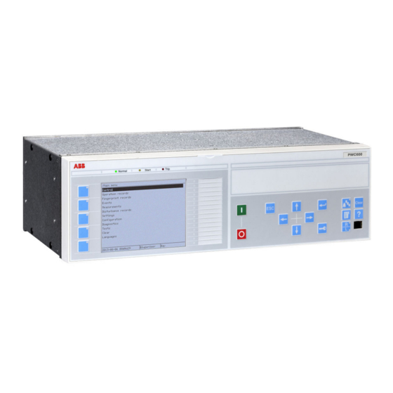
Describes the elements of the Local Human-Machine Interface (LHMI), including display, buttons, LED indicators, and communication port.
Display
Details the LHMI display, a graphical monochrome display with 320 x 240 pixels, divided into four basic areas.
LEDs
Explains the LHMI status LEDs (Ready, Start, Trip) and programmable alarm LEDs, indicating states with colors and pages.
Keypad
Describes the LHMI keypad with object control, navigation, and command push buttons, including function keys and RJ-45 communication port.
Local HMI screen
Details the Local HMI screen, including identification and settings for display timeout, contrast level, and default screen.
Local HMI signals
Describes local HMI signals, including identification, function block, and input/output signals.
Controlled Switching and Monitoring
Introduction
Introduces function blocks core to controlled switching, their interdependencies, and the definition of controlled switching.
Operation principle
Explains how controlled switching avoids harmful transients and increases equipment life by controlling breaker instants.
Secondary system supervision
Breaker close/trip circuit monitoring TCSSCBR
Details the TCSSCBR function for supervising the circuit breaker control circuit, detecting faults, and operating after settable times.
Control
Selector mini switch VSGGIO
Describes the VSGGIO function for acquiring external switch positions and issuing switching commands.
IEC 61850 generic communication I/O functions DPGGIO
Explains the DPGGIO function block for sending double point indications via IEC 61850 station bus, used in interlocking and reservation logics.
Point-on-wave switching control SSCPOW
Details the SSCPOW function for generating synchronized closing and opening commands to circuit breaker poles based on user settings and system voltage.
Logic
Configurable logic blocks
Provides standard and Q/T configurable logic blocks and timers for adapting IED configuration to application needs.
Boolean 16 to integer conversion B16I
Transforms a set of 16 binary signals into an integer, with the output frozen at the last value if BLOCK input is active.
Boolean 16 to integer conversion with logic node representation B16IFCVI
Transforms a set of 16 binary signals into an integer using logic node representation, freezing output at last value.
Integer to boolean 16 conversion IB16A
Transforms an integer into a set of 16 binary signals, mapping the least significant bit to OUT1.
Logical function to determine the minimum and maximum value MINMAX
Determines the maximum and minimum values out of all inputs and identifies the channel number with the minimum (MIN) and maximum (MAX) value.
Elapsed time integrator with limit transgression and overflow supervision TEIGGIO
Accumulates elapsed time for which a binary input signal has been high, with supervision of limit transgression and overflow.
Comparator for integer inputs INTCOMP
Monitors the level of integer values relative to each other or to a fixed value for monitoring, supervision, interlocking, and other logics.
Comparator for real inputs REALCOMP
Monitors the level of real value signals relative to each other or to a fixed value, used for monitoring, supervision, interlocking, and other logics.
Monitoring
Measurements
Measurement functions for power system measurement, supervision, and reporting to local HMI, PCM600, or station level via IEC 61850.
Phase current measurement CMMXU
Measures phase currents (amplitude and angle) and provides calibration for better than class 0.5 accuracy.
Phase-phase voltage measurement VMMXU
Measures phase-to-phase voltage, amplitude and angle, available on outputs with corresponding supervision level output.
Voltage sequence measurement VMSQI
Measures voltage sequence quantities, providing positive, zero, and negative sequence, amplitude and angle.
Current sequence component measurement CMSQI
Measures current sequence quantities, providing positive, zero, and negative sequence, amplitude and angle.
Phase-neutral voltage measurement VNMMXU
Measures phase-to-neutral voltage, amplitude and angle, with supervision level output.
Disturbance report
Provides complete and reliable information about disturbances, facilitating system behavior understanding and analysis.
Indications
Logs binary input signals that changed status during a disturbance, providing information via local HMI for a straightforward overview.
Event recorder
Logs selected binary input signals connected to the Disturbance recorder function, up to 150 time-tagged events per recording.
Event list
Logs up to 1000 time-tagged events in a ring-buffer, continuously updated by binary signal status changes.
Trip value recorder
Calculates magnitude and phase angle of selected analog input signals before and during the fault for disturbance evaluation.
Station communication
IEC 61850-8-1 communication protocol
Details the IED's support for the IEC 61850-8-1 protocol for operational information and controls, including Ethernet and GOOSE.
GOOSE binary receive GOOSEBINRCV
Describes the GOOSEBINRCV function used to receive 16 binary values via IEC 61850 GOOSE messages.
GOOSE function block to receive a double point value GOOSEDPRCV
Explains the GOOSEDPRCV function block for receiving double point values using IEC 61850 protocol via GOOSE.
GOOSE function block to receive an integer value GOOSEINTRCV
Describes the GOOSEINTRCV function block for receiving integer values using IEC 61850 protocol via GOOSE.
GOOSE function block to receive a measurand value GOOSEMVRCV
Details the GOOSEMVRCV function block for receiving measured (analog) values using IEC 61850 protocol via GOOSE.
GOOSE function block to receive a single point value GOOSESPRCV
Explains the GOOSESPRCV function block for receiving single point values using IEC 61850 protocol via GOOSE.
IEC 61850-9-2(LE) merging unit
Describes the IEC 61850-9-2(LE) standard for process bus, defining Merging Units (MU) for transmitting sampled values.
Redundant station bus communication
Covers redundant station bus communication using IEC 62439-3 Edition 2, employing PRP for LAN1 and LAN1B.
Activity logging parameters ACTIVLOG
Details settings for activity logging, including definition of up to 6 external log servers for system events.
Basic IED functions
Self supervision with internal event list
Explains the self-supervision functions (INTERRSIG, SELFSUPEVLST) reacting to internal system events.
Time system
Covers time synchronization sources (SNTP, IRIG-B, PPS) and real-time clock operation, including startup and power-off behavior.
Parameter setting group handling
Describes the use of four setting groups to optimize IED operation for different power system conditions.
Test mode functionality TESTMODE
Explains how to activate test mode to block functions and perform tests, with manual unblocking of functions.
Analog signal processing for controlled switching application ANSGPROC
Processes voltage and current signals for controlled switching, extracting properties like zero-crossing timestamps and amplitudes.
Change lock function CHNGLCK
Used to block further changes to IED configuration and settings after commissioning is complete, preventing inadvertent modifications.
IED identifiers TERMINALID
Allows users to identify the individual IED in the system, substation, region, or country.
Product information PRODINF
Identifies the IED and provides important pre-set settings such as IEDProdType, ProductVer, SerialNo, etc.
Primary system values PRIMVAL
Identification
Identifies the PRIMVAL function as Primary system values.
Functionality
Sets the rated system frequency and phasor rotation under Main menu /Configuration /Power system / Primary values.
Settings
Provides settings for Frequency and Phase Rotation, influencing calculations and measurements.
Signal matrix for analog inputs SMAI
Functionality
Processes analog signals, providing RMS value, phase angle, frequency, and other information for various IED functions.
Settings
Contains settings for GlobalBaseSel, DFTReference, ConnectionType, and AnalogInputType for signal processing.
Selection of 3-phase signals 3PHSELECT
Identification
Identifies the 3PHSELECT function for selecting between two three-phase analog signals.
Functionality
Connects receiver functions to one of two three-phase analog signals, allowing selection via source selector setting.
Blocking logic
Provides a BLOCKOUT output to block other application functions during re-synchronization to the respective source.
Web server WEBSERVER
Identification
Identifies the WEBSERVER function for configuring IED access via web browser.
Functionality
Enables access to the IED through a web interface (WHMI) using a web browser for configuration.
Settings
Provides settings for operation mode, session timeout, HTTPS port number, and maximum concurrent users.
Operation principle
Explains how WEBSERVER works as an interface for accepting requests and sending data via HTML files and authority system.
IED physical connections
Protective earth connections
Specifies the requirement for earthing the IED with a 16.0 mm2 flat copper cable, emphasizing short earth leads.
Inputs
Details measuring inputs for CTs/VTs and auxiliary supply voltage inputs, including connector assignments and voltage ranges.
Binary inputs
Describes precision binary inputs used for accurate detection of status changes of main or auxiliary contacts.
Outputs for controlling and signaling
Details signal output contacts (SO) for configurable conditions and power output contacts (PO) for switchgear control.
Technical data
Dimensions
Provides IED dimensions (width, height, depth) and weight box specifications.
Power supply
Details power supply specifications, including nominal voltage, variation, maximum load, ripple, and interruption time.
Energizing inputs
Covers energizing inputs, without specific details in this section.
Measuring inputs
Specifies measuring inputs for frequency, current, and voltage, including operating ranges and accuracy.
Signal outputs
Lists signal outputs, including rated voltage, contact carry, and breaking capacity for power outputs and signaling outputs.
Power outputs
Details power output relays, with and without TCS function, specifying rated voltage, contact carry, and breaking capacity.
Data communication interfaces
Describes Ethernet interfaces (100BASE-TX, 100BASE-FX) and supported protocols like IEC 61850-8-1 and HTTPS.
Enclosure class
Specifies the degree of protection for the IED front, rear, sides, top, and bottom.
Ingress protection
Details the ingress protection ratings (IP) for the IED front, rear, sides, top, and bottom.
Environmental conditions and tests
Outlines environmental conditions (temperature, humidity, altitude) and tests (cold, dry heat, damp heat).
Electromagnetic compatibility tests
Lists EMC tests including burst disturbance, electrostatic discharge, and radio frequency interference tests.
Insulation tests
Specifies dielectric tests, impulse voltage tests, and insulation resistance measurements.
Mechanical tests
Details mechanical tests such as vibration, shock, bump, and seismic tests.
Product safety
Covers product safety requirements, including LV directive and relevant standards.
EMC compliance
States compliance with EMC directive and relevant standards.
Need help?
Do you have a question about the Switchsync PWC600 and is the answer not in the manual?
Questions and answers