Bell System bellissimo Installation & Operation Manual
Video door entry system
2-72 way
Hide thumbs
Also See for bellissimo:
- Installation & operation manual (40 pages) ,
- User instructions (4 pages) ,
- Installation & operation manual (14 pages)
Table of Contents
Advertisement
Bell System (Telephones) Ltd.
issimo
bell
Video Door Entry System
2-72 Way
Installation & Operation Manual
This manual applies to the following: –
BSD8/72 2 to 72 Way Door Controller –
Version 2 Build 6 onward
BSC4 Video Controller –
Version 2 Build 4 onward
BS Colour Videophone –
Version 3
BSA Audio Phone –
Version 1
PD-098 Issue 4B
January 2015
Advertisement
Table of Contents

Related Manuals for Bell System bellissimo


Summary of Contents for Bell System bellissimo
- Page 1 Bell System (Telephones) Ltd. issimo bell Video Door Entry System 2-72 Way Installation & Operation Manual This manual applies to the following: – BSD8/72 2 to 72 Way Door Controller – Version 2 Build 6 onward BSC4 Video Controller –...
- Page 2 issimo bell 2-72 Way Video Entry System PD-098 Issue 4B Installation and Operating Manual Page 2 of 44...
-
Page 3: Table Of Contents
DIAGRAM I – OPTION DETAILS ..................36 DIAGRAM J – 2-72 WAY ADDITIONAL DDA WIRING ............ 37 DIAGRAM K – BELLISSIMO COMBINED SYSTEM CONNECTIONS ......38 DIAGRAM L – ACT PROXIMITY TO BELLISSIMO CONNECTIONS ......39 SAFETY INFORMATION AND DECLARATIONS ............42 PD-098 Issue 4B... -
Page 4: Introduction
Introduction Description A bellissimo video door entry system consists of a door panel, positioned at the entrance of a building, video telephones (videophone), placed inside of the building for the convenience of the occupants and a power supply and controller which are usually located inside an electrical cupboard. -
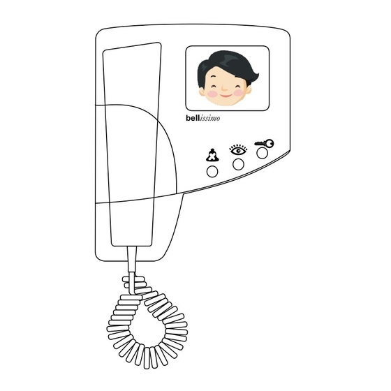
Page 5: Bellissimo Colour Videophone
issimo bell 2-72 Way Video Entry System issimo bell Colour Videophone Button Lamp Steady Flashing Mute On/Off Videophone is muted Videophone is off-hook View / Camera select Amber Call in progress Ringing Lock Green Door is open Press to release lock PD-098 Issue 4B Installation and Operating Manual Page 5 of 44... -
Page 6: Basic System Operation
issimo bell 2-72 Way Video Entry System Basic System Operation Call sequence When the call button is pressed at the entrance panel it causes the videophone to ring and the amber view lamp to flash. The videophone will continue to ring for up to 30 seconds or until the resident responds by picking up the handset. - Page 7 2-72 Way Video Entry System User Activation (CCTV Mode) User activation is a feature of the bellissimo 1 way system and is not available on multi- way systems. User activation is generally not recommended on larger systems as the conflicting demands of residents and callers can result in confusion and erroneous fault reports.
- Page 8 2-72 Way Video Entry System Multiple Entrances The bellissimo system allows multiple entrances to be catered for by the addition of a door controller and entrance panel for each entrance and additional power supplies. Gate and Block Systems Sites with two or more blocks sharing one or more site entrances are catered for with our BSSW Gate controller.
-
Page 9: Design Considerations
2-72 Way Video Entry System Design Considerations Equipment List A BS-n bellissimo Video Kit (where n is the no of ways) comprises the following: - Model No Description N x BS Videophone (N is the no of phones) 1 x BSPn Standard panel with a speech unit and camera. -
Page 10: Power Supply Requirements
The gate switch controller BSSW is wired between the block door controllers and the video controllers, so would normally be wall mounted next to a door controller. For further details see the “bellissimo and Bellcall Manual Gate and Block (PD-120)”. Separately Powered Videophones... - Page 11 issimo bell 2-72 Way Video Entry System Exact power supply requirements depend upon many factors. The number of power supplies included within a standard ‘kit’ or quotation assumes that all controllers are installed in one location and that there are no extensions. The following table gives examples of the minimum number of controllers and power supplies for a given number of entrance doors and flats.
-
Page 12: Cable Specification
(or greater) power cable as tabulated below. Cat5 cable has a known performance for the transmission of video signals, whilst telephone or alarm cables are not suitable. Bell System will be unable to offer any warranty or support for systems installed using incorrect cables. -
Page 13: Cable Distances - Colour Videophones
issimo bell 2-72 Way Video Entry System Cable Distances – Colour Videophones Video Controller to Videophone System Distance Cable Comments Single videophone per < 150m 1 x Cat5 output > 300m 1 x Cat5 2 x 1mm Single videophone + 3 <... -
Page 14: Installation & Commissioning
issimo bell 2-72 Way Video Entry System Installation & Commissioning Checklist The following checklist is a summary of what is required. Refer to the relevant pages for further details. ● Review the section headed ‘Safety Information’ on page 42. ● Ensure that ‘Design Considerations’ on page 9 have been understood. ●... - Page 15 The BSA audio phone can be used as a lower cost alternative to an extension videophone. It is styled like the bellissimo videophone. The phone is manufactured in white and grey high-impact ABS plastic that imparts high durability and compliments most wall furnishings.
-
Page 16: Commissioning
“Time clock common”. See the detailed diagram on page 36. Commissioning The major components of the bellissimo Video system are fitted with high quality pluggable screw terminal blocks. This enables all the connections to the system to be fully completed, whilst easily isolating individual pieces of equipment during testing and commissioning. -
Page 17: Bsd8/72 Door Controller Switch Settings
issimo bell 2-72 Way Video Entry System BSD8/72 Door Controller Switch Settings Talking Time/Videophone Active DIP SW1 (1-4) Talk Time On On On On 15s SW1 SW2 SW3 On On On Off 20s On On Off On 30s On On Off Off 45s On Off On On 60s On Off On Off 75s On Off Off On 90s... - Page 18 issimo bell 2-72 Way Video Entry System Lock Operate Time Dip SW2 (1-3) Lock Time On On On 3s* SW1 SW2 SW3 On On Off 4s On Off On 5s On Off Off 6s Off On On 8s Off On Off 10s Off Off On 15s Off Off Off 20s OFF ↔...
-
Page 19: Bsd8/72 Door Controller Jumper Settings
The “Video Gain” jumper on door controllers should always be set to “0” unless directed by ‘Bell System Technical Support’. This jumper is only required on some systems with very long camera to videophone cable runs well in excess of 150m. Inappropriate use of this jumper with short runs will cause picture problems. -
Page 20: Bsc4 Video Controller Settings
The “Video Gain” jumper on video controllers should always be set to “0” unless directed by Bell System Technical. This jumper is only required on some systems with very long camera to videophone cable runs well in excess of 150m. Inappropriate use of this jumper with short runs will cause picture problems. - Page 21 The use of this jumper precludes the use of Odd/Even addressing by PROG pins 1-2, if both are required contact Bell System Technical. The jumper is stored on pins 4-5. Custom Alternate Addressing Special versions of the BSC4 can be ordered to allow addressing above 6413.
-
Page 22: Bs Videophone Switch Settings
issimo bell 2-72 Way Video Entry System BS Videophone Switch Settings Mute Time Settings (1-4) Settings Mute Time On On On On Disabled¹ On On On Off 2 minutes On On Off On 5 minutes On On Off Off 10 minutes On Off On On 15 minutes On Off On Off 20 minutes OFF ↔... -
Page 23: Troubleshooting
issimo bell 2-72 Way Video Entry System Troubleshooting Common Faults A very high percentage of calls to our technical support number, regarding new installations, are resolved to faulty wiring. The reasons for these are various: - Broken cores, especially short links, sometimes broken inside the insulation! Connectors clamped onto the insulation instead of copper. - Page 24 issimo bell 2-72 Way Video Entry System BSC4 Video Controller Tests When the system is idle (no calls in progress) pressing the ‘Test’ button activates the ‘Audio On, ‘Status’ and one of the ‘Select n’ LED’s for 3S. If the system is not idle (Version 2 only) pressing the ‘Test’...
- Page 25 issimo bell 2-72 Way Video Entry System Video Problems Broken or missing Video + or Video – wire. Blank picture when: - Calling videophone or Cameras incorrectly configured refer to SW2-6 Pressing view settings on page 18 Call is from an audio only panel.
-
Page 26: Specifications
issimo bell 2-72 Way Video Entry System Specifications BSD8/72 Door controller Size BSD8: 185mm x 230mm x 42mm BSD72: 360mm x 240mm x 40mm Supply Voltage 10.8V min, 13.8V typical, 15V max Current Consumption 80mA idle @13.8V, 250mA active includes speech not cameras Model CAMBS-C Colour Camera Size 60mm x 57mm x 31mm... - Page 27 issimo bell 2-72 Way Video Entry System PS4 Power Supply Size 236mm x 105mm x 81mm Output Voltage (regulated) 13.5V d.c. min, 13.8V d.c. nom, 14.1V d.c. max Output Current 3A continuous, 4A peak (5 minutes max) Mains Supply Internal Fuse Not user replaceable Supply Voltage 230V 50Hz nominal...
-
Page 28: Diagram A - 2-72 Way Basic System Overview Cabling
issimo bell 2-72 Way Video Entry System Diagram A – 2-72 Way Basic System Overview Cabling PD-098 Issue 4B Installation and Operating Manual Page 28 of 44... -
Page 29: Diagram B - Large System Overview
issimo bell 2-72 Way Video Entry System Diagram B – Large system Overview Illustration of Power Supply Distribution Further Further Controllers Entrances 2 x 1mm² BSC4 Video Passthru Controller Cat5 Input 2 x 1mm² Cat5 Input Door BSD8 (2-8 way) Panel BSD72 (9-72 way) Output... -
Page 30: Diagram C - Bsd8 Pcb Detail
Audio Video High High Cam1 Cam2 Video Gain 4 3 2 1 0 Label BSD8/72 Test Version No Build No Status bellissimo Prog Door Controller Lock BSD8 Power Calls Exit Door Lock Door Panel Entrance Power Supply PD-098 Issue 4B... -
Page 31: Diagram D - 2-72 Way Basic System Wiring Detail
issimo bell 2-72 Way Video Entry System Diagram D – 2-72 Way Basic System Wiring Detail PD-098 Issue 4B Installation and Operating Manual Page 31 of 44... -
Page 32: Diagram E - 2-72 Way Multiple Entrance Wiring Detail
issimo bell 2-72 Way Video Entry System Diagram E – 2-72 Way Multiple Entrance Wiring Detail PD-098 Issue 4B Installation and Operating Manual Page 32 of 44... -
Page 33: Diagram F - Extension Videophone Wiring
issimo bell 2-72 Way Video Entry System Diagram F – Extension Videophone Wiring When alternate power wires are required replace Blu and W/Blu with the alternate wires. Note. For each cable run :- Only one unit must be Master (Recommend the first unit) ... -
Page 34: Diagram G - Videophone Local Power Wiring
issimo bell 2-72 Way Video Entry System Diagram G – Videophone Local Power Wiring Where more than one extension video unit is required to provide "auto display" then additional power supplies will be required Note. For each cable run :- ... -
Page 35: Diagram H - Videophone Connections
issimo bell 2-72 Way Video Entry System Diagram H – Videophone Connections Local Bell Connection This is for a standard bell push with volt free contacts, or any other volt free contact. An illuminated bell push is not catered for. Auxiliary Ring Circuit Primarily included for activating third party DDA devices the auxiliary ring output consists of a pair of volt free contacts which close while the phone is ringing. -
Page 36: Diagram I - Option Details
issimo bell 2-72 Way Video Entry System Diagram I – Option Details Camera Termination Options Cameras may be wired in either twisted pair or coax and shared with other equipment. Twisted Pair Through Connection Twisted Pair Termination From From To other Camera Camera equipment... -
Page 37: Diagram J - 2-72 Way Additional Dda Wiring
issimo bell 2-72 Way Video Entry System Diagram J – 2-72 Way Additional DDA Wiring PD-098 Issue 4B Installation and Operating Manual Page 37 of 44... -
Page 38: Diagram K - Bellissimo Combined System Connections
2-72 Way Video Entry System Diagram K – bellissimo Combined System Connections Connecting a Bellcode Coded Access Controller Connect the lock release as per this manual. Leave the Bellcode controller set to fail secure, the BSD controller sets the lock type. -
Page 39: Diagram L - Act Proximity To Bellissimo Connections
2-72 Way Video Entry System Diagram L – ACT Proximity to bellissimo Connections ACT 1000/2000/3000 Proximity Controller ACT 100e Proximity Extender Notes 1. Connect the lock release or Maglock using the ACT Manuals. 2. Leave the BSD controller set to Fail Secure regardless of the type of release used. - Page 40 issimo bell 2-72 Way Video Entry System PD-098 Issue 4B Installation and Operating Manual Page 40 of 44...
- Page 41 issimo bell 2-72 Way Video Entry System PD-098 Issue 4B Installation and Operating Manual Page 41 of 44...
-
Page 42: Safety Information And Declarations
issimo bell 2-72 Way Video Entry System Safety Information and Declarations Connections to the 240VAC mains supply must be carried out by a qualified electrician or similar competent person, and made in accordance with current legislative requirements. A two-pole switch (as provided by a Consumer Unit or Switch-Fuse) must be included to isolate both Live and Neutral during Installation or Maintenance. - Page 43 issimo bell 2-72 Way Video Entry System PD-098 Issue 4B Installation and Operating Manual Page 43 of 44...
- Page 44 2-72 Way Video Entry System Bell System (Telephones) Ltd. Presley Way, Crown Hill, Milton Keynes MK8 0ET. Tel: 01908 261106 (Sales and Technical Support) FAX: 01908 261116 Local rate numbers Tel: 0845 121 4008 (Sales and Technical Support) FAX: 0845 121 4009 E-mail: sales@bellsystem.co.uk...
Need help?
Do you have a question about the bellissimo and is the answer not in the manual?
Questions and answers