
Subscribe to Our Youtube Channel
Related Manuals for Guardall PX18


Summary of Contents for Guardall PX18
-
Page 1: User Manual
User Manual Issue D... -
Page 2: Table Of Contents
..........................5 YSTEM EYPADS Electronic Keys ..........................5 ............................5 EYSWITCH Proximity Cards/Fobs ........................5 ....................... 5 PERATION USING THE SYSTEM..........................6 (PX18/34)..........................6 ..............................6 ..........................7 EMOTE ERVICE ..........................7 NCORRECT ODES SET ................................. 8 ........................8 ETTING FROM A KEYPAD .......................... - Page 3 PX User Manual – Issue D LOGS ..............................20 TIME..............................20 HOLIDAY .............................. 21 SCHEDULE (PX18/34) ......................... 21 SCHEDULE (PX80/PX500) ........................22 SET GROUP ............................22 LATE WORK (PX80/500) ........................22 BYPASS..............................23 CHIME..............................24 PRINT TEXT ............................24 PRINT HOLS............................24 IDENTIFY USER...........................
-
Page 4: Introduction
The panel has a wide range of features, which are programmed by the engineer on installation, to suit the security requirements of the particular installation. Some of the features may be reprogrammed, edited, or viewed as required by an authorised user. Feature PX18 PX34 PX80 PX500 Max. -
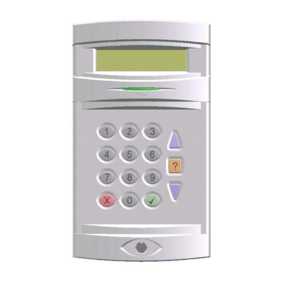
Page 5: Operator Controls And Displays
A user PIN code can be replaced by a proximity card or fob if the keypad is fitted with the optional proximity reader. All Guardall proximity cards and fobs are manufactured with a unique code and duplicate cards or fobs cannot be obtained. Spare or replacement cards or fobs can be obtained from the installation company. -
Page 6: Using The System
Refer to appendix D for details. Information about the system may be displayed when logging on. Refer to appendix E for details. Easy Set (PX18/34) If your system is programmed with the easy set option then all PIN codes are 4 digits long and PIN codes can be entered without confirming with the button. -
Page 7: Remote Service
12:00 Mon 27 Sep Guardall Incorrect Codes If Easy Set is not programmed and an incorrect user code is entered, the incorrect code message will be displayed for a few seconds or until another key is pressed. The installation engineer will have programmed a limit on the number of incorrect code attempts that can be made. -
Page 8: Set
1. A user request on a keypad 2. A user activating a keyswitch 3. Automatically by a timer schedule 4. Remotely from a PC using the Guardall GuardStation software 5. A user request on an ACM Proximity Reader. Setting modes include: 1. -
Page 9: Automatic Setting
PX User Manual – Issue D Automatic Setting The system may have been programmed by the installation engineer to automatically set all or parts of the system according to a pre-programmed schedule. The schedule will have been programmed to take into account the normal closing time, non-working days and holidays. The schedule may be configured for any set mode. -
Page 10: Setting Faults
PX User Manual – Issue D Setting Faults If the group cannot set a message will be displayed. This can occur at the start of setting or at the end of the exit time depending on how your system is set up and when the fault occurs. If a fault occurs during the exit time the exit tone will change to a warning tone. -
Page 11: Unset
2. A user activating a keyswitch 3. Automatically by a timer schedule 4. Remotely from a PC using the Guardall GuardStation software 5. A user request on an ACM Proximity Reader. Your installation engineer should advise which of the above options have been programmed on your system. -
Page 12: Unsetting From A Keyswitch
PX User Manual – Issue D Unsetting from a keyswitch To unset an area from a keyswitch, turn the keyswitch to the unset position. The area under the control of the keyswitch will immediately unset. Automatic Unsetting The system may have been programmed by the installation engineer to automatically unset all or parts of the system according to a pre-programmed schedule. -
Page 13: Reset
You will be issued with a special 6-digit PIN code. This PIN code can be used only once to reset the system. Enter the PIN to clear the engineer reset condition. 12:00 Mon 27 Sep Guardall reset code + 12:00 Mon 27 Sep... -
Page 14: Test
PX User Manual – Issue D Code-04 Test Each area of the system can be tested individually or all areas can be tested at the same time. The test time is limited to 1 hour. If the user does not end the test by the end of the test time then the panel will exit test mode automatically. -
Page 15: Engineer
PIN code to be entered. 05=Engineer When an engineer logs on to a keypad, all other Engineer keypads in the system will be inoperable and the Guardall display will show Out of Service . or time out (2 minutes) 12:00 Mon 27 Sep Guardall Once logged on the engineer working time is limited to 8 hours. -
Page 16: User
PX User Manual – Issue D Code-07 User A manager user can change the name, user code and authority for any user except the engineer. To modify a user’s details enter the user number in the range 2-max users. In the programming example user 3 is used. -
Page 17: Authority
A user can be programmed any combination of set groups. ACM 1, 2 On/Off This is a PX18/34 only option. If ACMs are fitted to the system then a user can be authorised for access through ACM doors 1 and/or 2. -
Page 18: Acm Authority (Px80/500)
PX User Manual – Issue D User Menu Code-4 ACM Authority (PX80/500) This option will only be available if at least one ACM is fitted to the system. Option Range Description Enable On/Off If this option is off no user ACM options will be displayed. ACM 1 - On/Off A user can be authorised for access through any combination... -
Page 19: Tel Number
PX User Manual – Issue D Code-08 Tel Number An authorised user can change any telephone number that has been programmed to use the speech format. This format is only available if SmartDial Speech dialler is fitted to the system. A telephone number of up to 16 digits can be programmed. -
Page 20: Logs
PX User Manual – Issue D Logs The panel logs all events that occur in the system. All events stored in the event log are numbered in the range 0-65535 (the event index). The event index will be reset to 0 when more than 65535 events have been recorded. -
Page 21: Holiday
To disable a holiday enter a date of 00:00. The start and end dates must be in chronological order. Holidays may be optionally programmed to apply to individual set groups Code-25 Schedule (PX18/34) A schedule can be used to: 1. Auto set and unset parts of the system 2. -
Page 22: Schedule (Px80/Px500)
PX User Manual – Issue D Code-25 Schedule (PX80/PX500) A schedule consists of 4 times for each day of the week and 4 times for days which are holidays. A schedule can be used to: 1. Auto set and unset parts of the system 2. -
Page 23: Bypass
PX User Manual – Issue D Code-30 Bypass The bypass option will only be available if a circuit(s) has been programmed as bypassable by the installation engineer. The bypass circuit option allows the user to bypass a circuit that is in a fault condition. -
Page 24: Chime
PX User Manual – Issue D Code-32 Chime Certain circuit types can be selected as chime circuits when unset. To select the chime function for a circuit, enter the circuit number. In the example chime is turned on for circuit 1. 32=Chime Circuit Number ___... -
Page 25: Identify User
PX User Manual – Issue D Code-52 Identify User This option allows a user to be identified by presenting the card/fob. 52=Identify User Present Card/Fob User 3 fob presented Unused card/fob presented Code Not Used User 3 J Smith User 20 fob presented User 20 J Black Code-71... -
Page 26: Cct Status
PX User Manual – Issue D Code-89 Cct Status 89=Cct Status Cct Status Cct 1 Normal Bypassed When the Cct Status option is selected the circuits that are on soak test, bypassed, isolated or shunted will be scrolled on the display. - 26 -... -
Page 27: Access Features
The PX access control system can be configured through a security system keypad or a PC running GuardStation™ Access. Guardall PX proximity cards or fobs may only be introduced to the system through a PX keypad with an integrated proximity reader. The ACM door input may be programmed as a circuit. -
Page 28: Add A/User
PX User Manual – Issue D Code-50 Add A/User This option will only be available if at least one ACM is fitted to the system. 50=Add A/User User 3 The first free user number is displayed Present Card/Fob The user number is automatically incremented when a Valid Card/Fob valid card/fob is presented. -
Page 29: Door Unlock
PX User Manual – Issue D Code-53 Door Unlock This option will only be available if at least one ACM is fitted to the system. An ACM door can be manually locked/unlocked from a keypad. An optional unlock time of up to 255 minutes can be programmed. -
Page 30: Appendix A - User Authorities
PX User Manual – Issue D Appendix A – User Authorities All user options with the appropriate authority level are shown in the table. Code Menu Option Unset Reset Test Engineer Code User Tel Number Log-Full Log-Cct Log-User Log-KP Log-Date Log-Alarm A/Log-Full A/Log-User... -
Page 31: Appendix B - Editing Text
PX User Manual – Issue D Appendix B – Editing Text A number of text descriptors may be changed by an authorised user. All changes to descriptors are logged. Item Max. Length Default User User xx Set group Group x Access control module ACM x User Number-03... - Page 32 PX User Manual – Issue D Event log only messages Log Text Additional Data Display Text Event Description 230v Fault NONE (see note) NONE Mains supply failed 230v OK NONE (see note) NONE Mains supply restored A/Set Fault Usnn, Area m Usnn, Am An area auto set with faults Active Circuit...
- Page 33 PX User Manual – Issue D Event log only messages Log Text Additional Data Display Text Event Description Head Count Number Number of activations of all circuits programmed with the head count option while the panel was unset. Isolate User nn, Circuit mmm Usnn Cctmmm Circuit isolated by user Isolate User nn, Concm Usnn, m...
- Page 34 PX User Manual – Issue D Event log only messages Log Text Additional Data Display Text Event Description Software Error A software error has been logged Temp Bypass Circuit nnn Cctnnn A circuit has been temporarily (until clear) bypassed TX Off TX channel N off TX On TX channel N on...
-
Page 35: Appendix D - Menu Restrictions
PX User Manual – Issue D Appendix D - Menu Restrictions If a menu number is entered and the option is not available, then a reason will be displayed. For example if no area is set and you select unset the panel will prompt with the reason the unset option is not available. -
Page 36: Appendix E - Log On Messages
PX User Manual – Issue D Appendix E - Log On Messages When a user logs on, the system may display a special message(s) before the normal menu is displayed. The special messages are shown in the table. Message Reason Alarm Abort User logs on within the alarm abort period (programmable option) Call Engineer... -
Page 37: Appendix F - System Details
PX User Manual – Issue D Appendix F - System Details Number of Areas Number of keypads Number of Circuits Number of Users Service Number Contract Number Keypads Number Location Set Groups Number Description Areas - 37 -... -
Page 38: Circuits
PX User Manual – Issue D Circuits Number Description Location Cct 1 Cct 2 Cct 3 Cct 4 Cct 5 Cct 6 Cct 7 Cct 8 Cct 9 Cct 10 Cct 11 Cct 12 Cct 13 Cct 14 Cct 15 Cct 16 Cct 17 Cct 18... -
Page 39: Users
PX User Manual – Issue D Number Description Location Cct 28 Cct 29 Cct 30 Cct 31 Cct 32 Cct 33 Cct 34 Users Number Description Areas - 39 -... - Page 40 Guardall Limited Lochend Industrial Estate Newbridge Edinburgh EH28 8PL Tel: 0131-333-2900 FAX: 0131-333-4919 Technical Hotline: 0131-333-3802 Part Number: 320680-0D...
Need help?
Do you have a question about the PX18 and is the answer not in the manual?
Questions and answers