Table of Contents
Advertisement
Advertisement
Table of Contents

Related Manuals for Guardall Windsor 500


Summary of Contents for Guardall Windsor 500
- Page 1 Windsor 500 Engineer Manual Issue C...
-
Page 2: Table Of Contents
Windsor 500 Engineer Manual - Issue C Contents Contents ......................2 System Overview ................... 4 Software Differences ......................4 System Components ......................4 Main Control Unit ........................5 Concentrators ........................5 User Interfaces ........................5 Communicators........................5 Output Devices........................6 Default Display....................6 Windsor Menus ....................7 Menu Restrictions.................. - Page 3 Windsor 500 Engineer Manual - Issue C Copy......................22 Print....................... 23 Full............................23 Changes..........................23 Text............................23 EvProg ..........................23 Soak ......................24 Cct ............................24 Duration ..........................24 Limit .............................24 Check ......................25 Conc .............................25 Ccts ............................25 Circuit Responses ......................26 KPs ............................26 Inputs ...........................27 Diagnostics..........................27 Battery Test ........................27...
-
Page 4: System Overview
Windsor 500 Engineer Manual - Issue C System Overview Windsor is a highly versatile control panel which can be fully programmed on site through a keypad or remotely using a PC. Windsor can be programmed with up to 7 individual areas and 128 circuits. -
Page 5: Main Control Unit
Windsor 500 Engineer Manual - Issue C System Components Main Control Unit The main control unit is housed in a metal case and contains a single PCB. The PCB incorporates a 2 Amp power supply. The main control unit can also have a number of expansion PCBs fitted on an internal serial bus. -
Page 6: Output Devices
Windsor 500 Engineer Manual - Issue C System Components Output Devices Windsor can address up to 19 output devices. There are a number of different output device types; • ISB 8 output relay card (NO and NC contacts) • ISB 8 output TX card •... -
Page 7: Windsor Menus
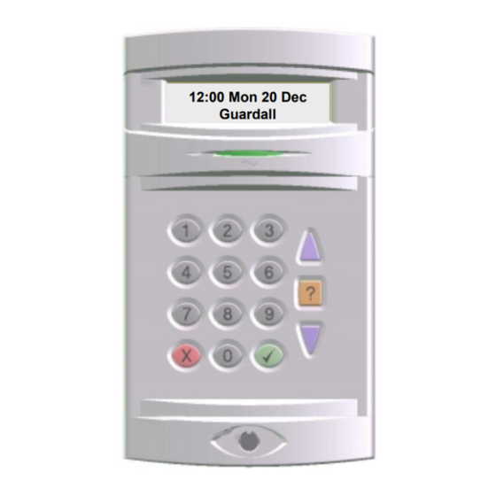
Windsor 500 Engineer Manual - Issue C Windsor Menus A Windsor menu consists of a list of options. Each option has a number and a prompt. As an example when you enter a valid PIN code the display may look something like that shown below. -
Page 8: Menu Restrictions
Windsor 500 Engineer Manual - Issue C Menu Restrictions All of the options on a page are not normally available at the same time. There are many reasons why an option is not available. If you think an option should be available but the prompt is not on display then press the corresponding button and Windsor will display an appropriate message. -
Page 9: Reset
Windsor 500 Engineer Manual - Issue C User page 1 Reset The reset option will only be on display if an alarm has occurred. This can be either an alarm when Windsor was set or when unset. The reset menu option will only be displayed if Windsor is unset and only if the user has chosen not to unset after the alarm log has been displayed. -
Page 10: Set
Windsor 500 Engineer Manual - Issue C User page 1 The set option will only be displayed if one or more of the areas that the user is authorised to set on the keypad is unset. Windsor may also be set by a Key circuit (see Circuit edit) or by a timer (see EvProg edit). -
Page 11: Log
Windsor 500 Engineer Manual - Issue C User page 1 The alarm log menu option will normally only be on display if the user is unable to reset after an alarm has occurred. A user can choose not to reset a log when the log is automatically displayed and then use the log menu option to print the alarm events. -
Page 12: Eng
Windsor 500 Engineer Manual - Issue C An engineer can program 24Hr, NA and ER circuits as detectors. Circuits programmed as detectors can be tested manually or automatically at a programmed time (see Detector edit). This is only useful if you are using sensors which have a test input (such as a vibration sensor). -
Page 13: Text Library
Windsor 500 Engineer Manual - Issue C All text descriptors can be up to 12 characters long and may contain any of the following characters; “ABCDEFGHIJKLMNOPQRSTUVWXYZabcdefghijklmnopqrstuvwxyz .- /#%^&*@<>0123456789” When you edit a text descriptor the first letter will be flashing. You can either use the ↑ and ↓... -
Page 14: Light
Windsor 500 Engineer Manual - Issue C User page 1 Light Windsor can be programmed with up to 4 lights zones. All of the light zone options are accessible to the engineer. A manager or ordinary user can program all light options except the light output channel. -
Page 15: Bypass
Windsor 500 Engineer Manual - Issue C User page 1 Bypass Windsor can be programmed to allow circuits to be bypassed. Each circuit can be programmed in any combination of 6 bypass groups and users can be programmed with authority over any combination of bypass groups. Not all users have the authority to bypass (see Users edit). -
Page 16: Event Log
Windsor 500 Engineer Manual - Issue C User page 2 Event Log Windsor can store up to 300 events in the event log. The event log may be displayed or printed in full or in filtered form. 1=Circuit There are 4 event log filter options. - Page 17 Windsor 500 Engineer Manual - Issue C Event log and Area log messages Log Text Additional Data Display Text Event Description Alarm Circuit nnn Cctnnn A Circuit alarm Auto Check Fail Circuit nnn Cctnnn A Circuit has failed to activate during the auto check period.
- Page 18 Windsor 500 Engineer Manual - Issue C Event log and Area log messages Log Text Additional Data Display Text Event Description Bat.Monitor Fail NONE NONE Battery voltage is low or not present during a battery test Beam Active Circuit nnn...
- Page 19 Windsor 500 Engineer Manual - Issue C Event log and Area log messages Log Text Additional Data Display Text Event Description Isolate (conc) User nn, m Usnn, m Concentrator isolated by user Key List Error User nn, Keypad m Usnn, KPm...
- Page 20 Windsor 500 Engineer Manual - Issue C Event log and Area log messages Log Text Additional Data Display Text Event Description Shunt Off Circuit nnn Cctnnn A master shunt circuit or the event programmer schedule has removed the shunt from a circuit...
-
Page 21: Users
Windsor 500 Engineer Manual - Issue C User page 2 Users All Windsor users must be programmed with an authority. A manager or engineer user can change a users authority. User 1 is fixed as an engineer authority and no other user can be programmed as an engineer. -
Page 22: Evprog
Windsor 500 Engineer Manual - Issue C User page 2 EvProg The event programmer menu is available to engineer, manager and ordinary users. The schedule option is only displayed to a manager or ordinary user if the User Edit option is programmed. -
Page 23: Print
Windsor 500 Engineer Manual - Issue C To copy to a single circuit enter the same circuit number as the first and last. The EVP copy option will copy a complete schedule to a range of schedules. The Days copy option will copy the times for 1 day to a range of days in same schedule. The days are entered as numbers in the range 0-6, with Monday represented by a 0. -
Page 24: Soak
Windsor 500 Engineer Manual - Issue C User page 3 (engineer only) Soak Windsor circuits can be put on soak for a programmable period. When a circuit is on soak there will be no audible alarm response. The soak response for each circuit and the number of allowed activations during the soak period from each circuit can be programmed. -
Page 25: Check
Windsor 500 Engineer Manual - Issue C User page 3 (engineer only) Check When all of the system components have been connected and configured the responses can be checked. 1=Conc There are 5 check mode options 2=Ccts 3=KPs 4=Inputs 5=Diagnostics... -
Page 26: Circuit Responses
Windsor 500 Engineer Manual - Issue C Circuit Check Mode Circuit Responses The table below shows the range of values that can be displayed for all types of external concentrator. The displayed state will always be Clear if the circuit is programmed as Off. If a circuit which is connected to an internal concentrator is tested the message “On Int Bus”... -
Page 27: Inputs
Windsor 500 Engineer Manual - Issue C The status of each keypad is displayed for a few seconds. KP-1 Clear No Reply, Tamper or Clear Configured/Not Configured Configured After the status of last keypad is reported Windsor will display the results of the check until a key is pressed. -
Page 28: Demo
Windsor 500 Engineer Manual - Issue C User page 3 (engineer only) Demo When the system has been programmed it can be demonstrated to the customer using demo mode. In demo mode movement detectors (programmed as NA types) are ignored. This allows an area or the system to be set by the normal exit route while the premises is occupied. -
Page 29: Smartcard
Windsor 500 Engineer Manual - Issue C User page 3 (engineer only) SmartCard This option only applies to Windsor Mark 1 (PC787) and software versions up to v1.40. SmartCard is a plug on non-volatile memory card capable of storing a number of Windsor configurations. -
Page 30: Appendix A - System Alarm Responses
Windsor 500 Engineer Manual - Issue C Appendix A - System Alarm Responses The Windsor system alarm responses for tamper, line fault, supply voltage monitoring and duress are detailed in this section. System Alarm Responses Tamper Windsor can identify a tamper from any circuit, keypad, concentrator, the external sounder and the case lid and off-the-wall tamper. -
Page 31: Supply Voltage
Windsor 500 Engineer Manual - Issue C Line Fault Response Set Response Unset Response Sounder Audio Strobe Sounder Audio Programmable Only one audible response, if programmed, is allowed in any unset period. The keypad line fault LED will be turned on until the line fault clears. The line fault LED will be on even if no user is logged on to the keypad. -
Page 32: Duress
Windsor 500 Engineer Manual - Issue C If the battery voltage falls to the power fail level then; • the message Power Fail is logged in the event log. • the power fail TX output is turned on. • if any area is set then the external sounder, strobe and the internal audio output will be turned on for the programmed sounder duration. -
Page 33: Appendix B - Text Library
Windsor 500 Engineer Manual - Issue C Appendix B - Text Library Number Text Number Text Accounts Master Admin Medical Alarm Microwave Alert Monitor Area Movement Office Attack PA Button Auxiliary Panel Bank Panic Partition Beam Passive Bedroom Perimeter Branch... - Page 35 Windsor 500 Engineer Manual - Issue C Windsor User Options - Page 2 1=Chime 2=KP Off 3=Event Log 4=User 5=Time 6=Keys 7=Evprog 8=Remote 9=Isolate 1=Full 1=Clock 1=Late 2=Filter 2=Date 2=Schedule 3=Sum.Time 3=Holiday 4=Win.Time 1=Area 1 Schudule 2=Area 2 Number- 1=Circuit...
-
Page 37: Change History
Windsor 500 Engineer Manual - Issue C Change History Change History Software Version 2.05 Issue B 1. Added multi-level contents section. 2. Changed 240v references to 230v. 3. Added footnote about SmartCard in the user menus section. 4. Added vault timer condition to the menu restrictions. -
Page 39: Issue C
Guardall Limited Lochend Industrial Estate Newbridge Edinburgh EH28 8PL Scotland Part No. 320489 (Issue C)
Need help?
Do you have a question about the Windsor 500 and is the answer not in the manual?
Questions and answers