
Related Manuals for Guardall Windsor 500


Summary of Contents for Guardall Windsor 500
-
Page 1: User Manual
Windsor 500 User Manual Technical Manuals Online! - http://www.tech-man.com Technical Manuals Online! - http://www.tech-man.com For Version 3 Software... -
Page 2: Table Of Contents
Windsor 500 User Manual - Issue C Contents Contents ..........................2 Introduction........................7 System Components ............................ 7 Programmable Features..........................7 Event Programmer............................7 System And Area Event Log ........................8 Security Lighting Controls........................... 8 Areas, Circuits and Groups ....................9 Common Area.............................. - Page 3 Windsor 500 User Manual - Issue C Dual PIN Operation ............................. 13 Logging on ........................14 Invalid PIN Code or Electronic Key ......................14 User Access Time ............................14 Engineer On Site ............................14 Display Formats....................... 15 Normal ‘Day’ Mode............................15 User Menus ........................
- Page 4 Windsor 500 User Manual - Issue C Aborting The Setting Procedure........................ 20 Setting with Warnings ..........................20 Setting Faults .............................. 21 Failure to Set after Exit Time ........................21 Automatic Setting ............................21 Unsetting Methods ......................23 General................................. 23 Entry Route Unsetting ..........................23 Unsetting Procedure .......................
- Page 5 Windsor 500 User Manual - Issue C Testing..........................31 Selecting Test Functions ........................... 31 Testing The External Sounder........................31 Testing The Internal Sounder ........................31 Testing The Strobe ............................. 32 Walk Test ..............................32 Unset Test Functions ..........................32 Panic Alarm Testing............................ 33 24 Hr Test..............................
- Page 6 Windsor 500 User Manual - Issue C ATM Bypass ........................45 Changing ATM PIN............................45 Selecting the Chime Function ..................47 Disabling a Keypad......................48 Changing User Authority ....................49 Changing the System Clock ................... 51 Programming Electronic Keys..................52 The Event Programmer ....................
-
Page 7: Introduction
Windsor 500 User Manual - Issue C Introduction The Windsor Electronic Intruder Alarm System is designed to provide secure protection for the client’s premises. The system is highly versatile permitting individual systems to be installed and programmed, to meet the particular security requirements of each installation. -
Page 8: System And Area Event Log
Keypad number or date. Security Lighting Controls Windsor 500 Systems are provided with facilities to control up to four individual light zones. If automatic lighting control is incorporated in the system, each light zone will be switched on automatically if a Lighting Detector detects movement. -
Page 9: Areas, Circuits And Groups
Circuits A maximum of 128 alarm circuits can be monitored by the Windsor 500 System. Each circuit is allocated a unique circuit number which is used to identify the particular circuit. Your installation engineer will have programmed each circuit to respond in a certain way when the circuit is activated, when the area is set and unset. -
Page 10: User Authority
Windsor 500 User Manual - Issue C User Authority The Windsor System can be programmed to accept up to 50 authorised users. The first three user numbers are pre-allocated as follows: User 0 System User (Automatic functions) User 1 Engineer... -
Page 11: Pin Codes
Windsor 500 User Manual - Issue C PIN Codes Each user is identified within the system by their user number. Each user number is allocated a unique four, five or six digit PIN (Personal identity Number) which is used to identify the user and to permit user access to the various system functions according to the authority level allocated. -
Page 12: Operator Controls And Displays
Windsor 500 User Manual - Issue C Operator Controls and Displays System Keypads 2 x 16 character LCD backlit display 15 button backlit keypad GUARDALL 09:48 QUIT HELP Status LEDs MAINS CALL ENGINEER READY LINE FAULT LATE WORKING MESSAGE SET WARNING... -
Page 13: Keypoints
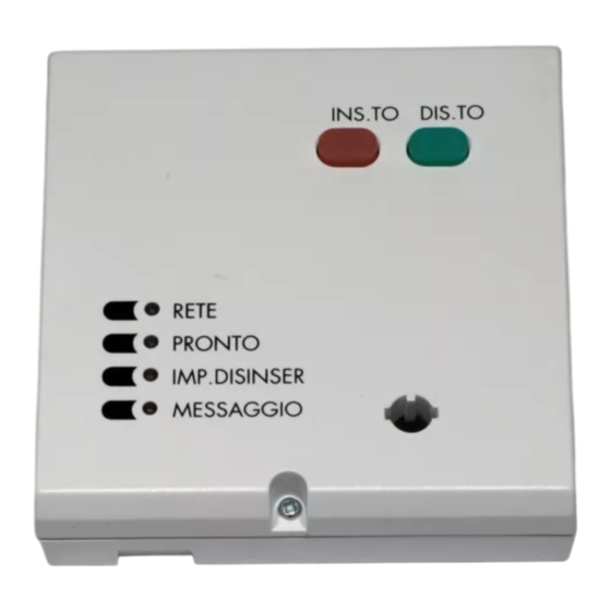
Windsor 500 User Manual - Issue C Keypoints UNSET Set and Unset backlit buttons Status LEDs MAINS READY Electronic key socket MESSAGE Keypoints can be fitted instead of any of the 8 (maximum) Keypads. Each Keypoint can be programmed to permit setting/unsetting of only one selected area or the complete system. -
Page 14: Logging On
Windsor 500 User Manual - Issue C Logging on A user logs on to the system by entering a user PIN (4 to 6 digit code) at a Keypad then presses ’Enter’. Alternatively the user can log on by inserting a valid electronic key at the Keypad or Keypoint. The system will check that the entered PIN code or Electronic Key is valid before permitting access to the system user functions. -
Page 15: Display Formats
Windsor 500 User Manual - Issue C Display Formats Normal ‘Day’ Mode When a Windsor is first powered up the display will default to displaying the date and time. The displayed format on each Keypad can be modified by any user by pressing the button to change the top line and the to change the bottom line. -
Page 16: User Menus
Windsor 500 User Manual - Issue C User Menus Menu Restrictions The display which appears on the Keypad LCD when a user logs on to the system will depend on the authority allocated to the user, which Keypad is used, the set condition of the area, any other Keypad activity, and any time restrictions governed by the event programmer. -
Page 17: Setting Methods
Windsor 500 User Manual - Issue C Setting Methods General An authorised user can set the complete system or partly set the system by area from a Keypad or Keypoint according to the user authority level, and the area authority allocated to the particular Keypad/Keypoint Alternatively, where the system event programmer has been programmed to set an area of the system at a predetermined time, the area will set automatically. -
Page 18: Keyswitch Setting
Windsor 500 User Manual - Issue C tone will operate until the ’Entry/Exit’ is closed or the ’Exit Time’ has expired. The user must leave the area by the prescribed ’Exit Route’. If a user deviates from the prescribed ’Exit Route’ during exit, the exit tone will change to a pulsing tone while the ’Non Exit Route Circuit’... -
Page 19: Setting Procedure
Windsor 500 User Manual - Issue C Setting Procedure Area or System Setting from a Keypad The combination of user authority and Keypad area authority may provide a choice of areas which can be set from a particular Keypad or a choice of setting the whole system. -
Page 20: Setting Using A Keypoint
Windsor 500 User Manual - Issue C 7. Select the area(s) to be set and these will now be displayed in the set status. Set:1+2 8. Select ↵ and the group set will take place. After the group has been set, the menu ↵... -
Page 21: Setting Faults
Windsor 500 User Manual - Issue C ↵ Workshop Possible ’Setting Warnings’ are as follows: 1. Circuits Bypassed 2. Circuits On Soak 3. Circuits isolated 4. Line Fault (appears as ’Setting Warning’ only when setting with telephone line fault is programmed as prohibited). - Page 22 Windsor 500 User Manual - Issue C programmed 'Late Working' time. The ‘Late Working' LED will be illuminated until the area is manually or automatically set. 4. If an extension facility is programmed, the user may extend the automatic setting time by the pre-...
-
Page 23: Unsetting Methods
Windsor 500 User Manual - Issue C Unsetting Methods General Unsetting of an area or system can only be requested by a user with authority to unset the particular area (or system) and from a Keypad or Keypoint programmed to permit unsetting of the area (or system) Unsetting can be initiated by a user request on a Keypad or Keypoint, by opening an entry circuit, by turning a Keyswitch to the 'Off ' position, or automatically if the event programmer is configured for ‘Auto Unsetting'. -
Page 24: Unsetting Procedure
Windsor 500 User Manual - Issue C Unsetting Procedure Unsetting an Area or System from a Keypad The combination of user authority and Keypad area authority provide a choice of areas which can be unset from a particular Keypad, or a choice of unsetting the whole system. If an area is already unset, the option to unset the area will not be shown. -
Page 25: Unsetting From A Keypoint
Windsor 500 User Manual - Issue C 1. If the Keypad has been configured for ‘Timed’ or ‘EnEx', on certain areas, these will Unset Workshop automatically unset. If not, the display will show the user menu. 2. Press ‘1’ to access the unsetting options. -
Page 26: Unsetting After An Alarm
Windsor 500 User Manual - Issue C Unsetting After an Alarm If an alarm condition has occurred during the ’Set’ period, the area sounder, audible Unset alarm and/or strobe may be operating. The action of unsetting the area (or system) will Public Area cancel all warning devices. -
Page 27: Resetting After An Alarm
Windsor 500 User Manual - Issue C Resetting After an Alarm General The resetting method programmed by the alarm company engineer for each area and the system will depend on the particular security requirements of the area or system. Customer Reset When programmed for ’Customer Reset’, the user can reset the system after viewing... -
Page 28: Guardall Managed Reset
Windsor 500 User Manual - Issue C Guardall Managed Reset If an area is configured for ‘Managed' Reset it enables the customer to reset the area (or system) after contacting the alarm company. 1. Enter your Pin Code and press ↵ . -
Page 29: Viewing The Logs
Windsor 500 User Manual - Issue C Viewing the Logs General Area logs can be viewed or printed by an authorised user or engineer. Alarm log events are automatically cleared when the area is reset or next set, providing circuits are clear or inactive. All area events are also recorded in the system event log. -
Page 30: Viewing/Printing The System Event Log
Windsor 500 User Manual - Issue C Viewing/Printing The System Event Log An Manager user can select the system event log for viewing/printing when the area or system is unset as follows: 1. Enter valid and authorised user code at a Keypad. -
Page 31: Testing
Windsor 500 User Manual - Issue C Testing Selecting Test Functions The ’Test’ option is shown on the user menu when a user authorised to test the area or system, logs on to a Keypad. To test the areas (or System) proceed as follows: 1. -
Page 32: Testing The Strobe
Windsor 500 User Manual - Issue C Testing The Strobe 1. Select 3 from the sounder menu to test the strobe light(s) 3=Strobe 2. The strobe light(s) for the area (or system) will be activated for the pre-programmed Strobe On test period (max. -
Page 33: Panic Alarm Testing
Windsor 500 User Manual - Issue C 1. Select 3 from the ’Test Functions’ menu. 2=Walk Test 3=Unset Test 2. The ’Unset Test Functions’ menu is displayed. Select required unset test function. 1=PA 2=24Hr 3=Detector Panic Alarm Testing 1. Selecting 1 from the ’Unset Test Function’ menu will permit the user to manually test... -
Page 34: Detector Test
Windsor 500 User Manual - Issue C 4. When the user returns to the Keypad, any circuits which have not been tested will be 24Hr Test shown on the Keypad display. On completion of tests the display will inform you that all All Tested tests are complete. -
Page 35: Editing Text Descriptors
Windsor 500 User Manual - Issue C Editing Text Descriptors General The text descriptors, which appear on the Keypad displays for circuits, bypass groups, areas, users names and company name, are normally programmed by the engineer on installation. However, a user with ’Manager’... - Page 36 Windsor 500 User Manual - Issue C Again you are prompted for a Text Number. Enter ‘09’, for example, and then confirm Text Number_ _ Circuit 2 now has the desired label. Should the text library not contain the desired label Cct number 2 ↵...
-
Page 37: Text Library
Windsor 500 User Manual - Issue C Text Library Number Text Number Text Accounts Master Admin Medical Alarm Microwave Alert Monitor Area Movement Office Attack PA Button Auxiliary Panel Bank Panic Partition Beam Passive Bedroom Perimeter Branch Cafe PIR B... -
Page 38: Modifying Light Controls
Windsor 500 User Manual - Issue C Modifying Light Controls General The engineer on installation normally programs the operation of security lighting on the Windsor. However, a user with ’Manager’ authority can modify and test the lighting zones as follows:- (a) Modify the ’On’... -
Page 39: Timed Control
Windsor 500 User Manual - Issue C Timed Control Timed control enables a light zone to be programmed to switch on and off at pre-programmed times. This gives a capability to provide courtesy lighting at necessary times e.g. light a driveway when people are coming home. -
Page 40: Manual Control
Windsor 500 User Manual - Issue C 6. Press ’Quit’ to return to the ’Light Zones Menu’ Quit 4=Dusk Time 5=Manual 6=Test Manual Control Selecting 'Manual Control' provides the user with the facility to manually turn the light zone ‘on’ or ‘off’, or to manually turn the zone ‘on’... -
Page 41: Testing Light Zones
Windsor 500 User Manual - Issue C Testing Light Zones The light zones are not tested as part of a ’Walk Test’. However light zones can be tested at any time by the user. 1. Select 6 from the ’Light zones’ menu. All Trigger Circuits in the selected light zone can be ‘Walk Tested’. -
Page 42: Changing Pin Codes
Windsor 500 User Manual - Issue C Changing PIN Codes General Any user can change their own PIN code at any time, provided the selected PIN code is not already being used. All user PIN code changes are recorded in the system event log. - Page 43 Windsor 500 User Manual - Issue C 6. The display will show the text descriptor for the selected user and give the Manager’ J Smith ↵ = Change PIN the option of changing the PIN code. Press ’Enter’ to change the user’s PIN code 7.
-
Page 44: Bypassing Circuits Or Groups
Windsor 500 User Manual - Issue C Bypassing Circuits or Groups Any circuits which have been programmed as ’By-passable’ can be bypassed by an ’Engineer’, ’Manager’ or ‘Ordinary User', providing they are authorised to do so, when the area is set. Bypassed circuits or groups will be automatically re-instated when the system is unset, providing doing so will not cause an alarm condition. -
Page 45: Atm Bypass
Windsor 500 User Manual - Issue C ATM Bypass The ATM Bypass’ function is only applicable to Windsor High Security Systems and is designed to permit a user with ’ATM Bypass’ authority to bypass one automatic telling machine (ATM) at any one time during servicing, etc. - Page 46 Windsor 500 User Manual - Issue C 4. Enter your new PIN NEW PIN Enter 5. Re-enter your new PIN. NEW PIN Re-enter 6. Press 'Quit’ to return to users menu. Quit 8=PIN ↵ = Next Page Technical Manuals Online! - http://www.tech-man.com Technical Manuals Online! - http://www.tech-man.com...
-
Page 47: Selecting The Chime Function
Windsor 500 User Manual - Issue C Selecting the Chime Function Certain circuit types (Entry Points, Alarm Circuits, Push Buttons etc..) can be selected as ’Chime’ circuits when the area or system is in the ’Set’ or ’Unset’ mode. Selecting ’Chime’ for a circuit will cause an audible ’Chime Tone’... -
Page 48: Disabling A Keypad
Windsor 500 User Manual - Issue C Disabling a Keypad A ‘Manager’' user can disable a Keypad in an authorised area if required, providing the area is unset. Disabling a Keypad will render all buttons on the Keypad inoperative, however the Keypad display will continue to operate normally. -
Page 49: Changing User Authority
Windsor 500 User Manual - Issue C Changing User Authority The user authority can be allocated and changed by a ’Manager’ user. To allocate or change the authority of a user, proceed as follows: 1. Log on to a Keypad using a PIN code with ’Manager’ authority. - Page 50 Windsor 500 User Manual - Issue C User Type User Authority None No access permitted. Manager All user functions for programmed areas. Ordinary All user functions for programmed areas, except viewing/printing the event log, isolating a Keypad, changing user authority and changing other user PIN numbers.
-
Page 51: Changing The System Clock
Windsor 500 User Manual - Issue C Changing the System Clock A user with ’Manager’ or Ordinary User’ authority can change the system clock by a maximum of 75 minutes in either direction. All changes to the system clock are recorded in the system event log. To change the system clock, proceed as follows: 1. -
Page 52: Programming Electronic Keys
Windsor 500 User Manual - Issue C Programming Electronic Keys A user with ’Manager’ authority can add Electronic Keys to replace the user PIN code allocated. This option is only available at a Keypad with an LCD display. All Electronic Key allocations are recorded in the system event log as PIN changes. -
Page 53: The Event Programmer
Windsor 500 User Manual - Issue C The Event Programmer Windsor 500 incorporates a time scheduler, referred to as the event programmer. The event programmer can have up to 4 different time schedules which can be applied to any of the control panel areas. Each schedule has a number of times for each day of the week. -
Page 54: Changing Late Working Days
Windsor 500 User Manual - Issue C Changing Late Working Days The late work option will only be available if there is a programmed Set 2 time for the day. If you log on during the set 1 warning period, and a set 2 time has been programmed, then the late working option will be displayed in place of the normal log on menu. -
Page 55: Viewing Scheduled Holiday Periods
Windsor 500 User Manual - Issue C 6. The display will then show the time options. The options available will depend on the 1=Shunt On type of software fitted to the panel (commercial of high security). 2=Open 1..7. Select the time to be viewed as shown on the menu. For example choose Open 1, i.e. -
Page 56: Remote Operation
Windsor 500 User Manual - Issue C Remote Operation The Windsor system can be controlled from a local or remote personal computer. To 7=EvProg ’log on’ to the system from a computer the Engineering communicator must be 8=Remote programmed by the installation engineer for the required remote functions. -
Page 57: Manager Isolate
Windsor 500 User Manual - Issue C Manager Isolate A user with ’Manager’ authority can isolate all circuits or concentrators. This option is only available if enabled by the engineer. All isolate operations are recorded in the system event log. To isolate a circuit, concentrator or all, proceed as follows : 1. -
Page 58: Isolate Concentrator
Windsor 500 User Manual - Issue C Isolate Concentrator The isolate concentrator operation enables a concentrator to be isolated in case of a fault. 1. Select 2 from the ’Isolate’ menu. 1=Circuit 2=Concentrator 2. Enter the concentrator number which requires isolation... -
Page 59: User Log Off
Windsor 500 User Manual - Issue C User Log Off 1. The user can log off the system at any time by pressing the ’Quit’ button from a main 7=EvProg menu only. 8=Remote Quit ↵ = Confirm Log 2. The display will show ’Confirm Log Off. -
Page 60: System Details
Windsor 500 User Manual - Issue C System Details General Number of Areas Number of Keypads Number of Keypoints Area Descriptions System Area l Area 2 Area 3 Area 4 Area 5 Area 6 Area 7 Bypass Group Descriptions Group 1... -
Page 61: Circuit Descriptions
Windsor 500 User Manual - Issue C Circuit Descriptions Cct 1 Cct 2 Cct 3 Cct 4 Cct 5 Cct 6 Cct 7 Cct 8 Cct 9 Cct 10 Cct 11 Cct 12 Cct 13 Cct 14 Cct 15 Cct 16... - Page 62 Windsor 500 User Manual - Issue C Cct 29 Cct 30 Cct 31 Cct 32 Cct 33 Cct 34 Cct 35 Cct 36 Cct 37 Cct 38 Cct 39 Cct 40 Cct 41 Cct 42 Cct 43 Cct 44 Cct 45...
- Page 63 Windsor 500 User Manual - Issue C Cct 58 Cct 59 Cct 60 Cct 61 Cct 62 Cct 63 Cct 64 Cct 65 Cct 66 Cct 67 Cct 68 Cct 69 Cct 70 Cct 71 Cct 72 Cct 73 Cct 74...
- Page 64 Windsor 500 User Manual - Issue C Cct 87 Cct 88 Cct 89 Cct 90 Cct 91 Cct 92 Cct 93 Cct 94 Cct 95 Cct 96 Cct 97 Cct 98 Cct 99 Cct 100 Cct 101 Cct 102 Cct 103...
- Page 65 Windsor 500 User Manual - Issue C Cct 116 Cct 117 Cct 118 Cct 119 Cct 120 Cct 121 Cct 122 Cct 123 Cct 124 Cct 125 Cct 126 Cct 127 Cct 128 Technical Manuals Online! - http://www.tech-man.com Technical Manuals Online! - http://www.tech-man.com...
-
Page 66: User Authorities & Descriptors
Windsor 500 User Manual - Issue C User Authorities & Descriptors User 0 User l User 2 User 3 User 4 User 5 User 6 User 7 User 8 User 9 User 10 User 11 User 12 User 13 User 14... - Page 67 Windsor 500 User Manual - Issue C User 27 User 28 User 29 User 30 User 31 User 32 User 33 User 34 User 35 User 36 User 37 User 38 User 39 User 40 User 41 User 42 User 43...
-
Page 68: Event Log And Area Log Messages
Windsor 500 User Manual - Issue C Event Log and Area Log Messages Event log and Area log messages Log Text Additional Data Display Text Event Description Alarm Circuit nnn Cctnnn A Circuit alarm Auto Check Fail Circuit nnn Cctnnn... - Page 69 Windsor 500 User Manual - Issue C Event log and Area log messages Log Text Additional Data Display Text Event Description Circuit nnn Cctnnn Auxiliary type circuit alarms Bat. Monitor Fail NONE NONE Battery voltage is low or not present during a...
- Page 70 Windsor 500 User Manual - Issue C Event log and Area log messages Log Text Additional Data Display Text Event Description Isolate User nn, Circuit nnn Usnn Cctnnn Circuit isolated by user Isolate (conc) User nn, n Usnn, n Concentrator isolated by user Key Set Req.
- Page 71 Windsor 500 User Manual - Issue C Event log and Area log messages Log Text Additional Data Display Text Event Description Shunt On Circuit nnn Cctnnn A master shunt circuit or the event programmer schedule has shunted a circuit Soak Alarm...
- Page 72 Technical Manuals Online! - http://www.tech-man.com Technical Manuals Online! - http://www.tech-man.com...
- Page 73 Windsor 500 User Manual - Issue C Windsor User Options - Page 2 1=Chim e 2 =KP Off 3=Event Log 4=User 5=Time 6=Keys 7=Evprog 8=Remote 9=Isolate 1=Full 1=Clock 1=Late Work 2=Filter 2=Date 2=Schedule 3=Sum.Tim 3=Holiday e 4 =Win.Time 1=Area Schudule...
- Page 74 Guardall Limited Lochend Industrial Estate Newbridge Edinburgh EH28 8PL Tel: 0131-333-2900 FAX: 0131-333-4919 Technical Hotline: 0131-333-3802 Technical Manuals Online! - http://www.tech-man.com Technical Manuals Online! - http://www.tech-man.com Part Number: 320513-0C...
Need help?
Do you have a question about the Windsor 500 and is the answer not in the manual?
Questions and answers