Table of Contents
Advertisement
Quick Links
Advertisement
Table of Contents

Subscribe to Our Youtube Channel
Summary of Contents for Simpson 2865
- Page 1 2865 and 2866 3-½ Digit Panel Instruments INSTRUCTION MANUAL...
- Page 2 SIMPSON ELEC- TRIC COMPANY neither assumes nor authorizes any other persons to assume for it any other liability in connection with the sales of its products.
- Page 3 0.15 microfarad capacitor connected between the terminals of the measur- ing instrument. The leakage current is that portion of the current that flows through the resistor. The Simpson Model 229-Series 2 AC Leakage Current Tester meets the ANSI C39.5 requirements for the measurement of AC leakage current and can be used for this purpose.
-
Page 4: Table Of Contents
2. INSTALLATION .................. 8 2.1 Panel Mounting Instructions ..............8 2.2 Power Source Requirements ..............8 2.3 Connections ................... 8 3. SERVICING INSTRUCTIONS ............9 3.1 Case and Front Cover Removal ............10 3.2 Line Fuse Replacement (2865 only) ........... 10... -
Page 5: Introduction
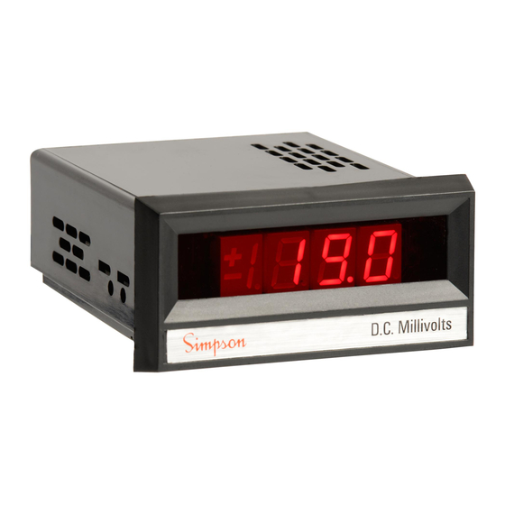
INTRODUCTION General The Simpson 2865 and 2866 (hereafter referred to as the 2865 or 2866 or the Instruments) are 3½-digit, panel-mounted instruments that provide visual indica- tion for either DC voltage or DC current measurement. Both Instruments feature 0.1 percent accuracy using solid-state integrated circuit electronics. - Page 6 10 pA maximum at reference con- ditions Full Range Step Response: 1 second (to rated accuracy) Norm. Mode Rejection: 50 dB minimum at 60 Hz Com. Mode Rejection: 90 dB minimum (2865 only) (with 1 kV unbalance at 60 Hz)
-
Page 7: Theory Of Operation
10. Rated Circuit-To-Ground Voltage*: (Maximum Common Mode Voltage) 2865: 250 VDC between either input ter- minal and power line ground 2866: –4.0 to +4.5 VDC between the com- mon (–) input terminal and the power source common (5 VDC re-... -
Page 8: Installation
Check that the power designation on top of the case agrees with the power source to be used. The Model 2865 is wired at the factory for 120 volts AC operation (see Table 1). For 240 volt operation, be sure that the power line ground connection of the... -
Page 9: Connections
5 VDC operation, requiring approximately 200 mA. Connections Refer to Figure 3 for the wiring diagram of the Model 2865 or to Figure 4 for the wiring diagram of the Model 2866. Do not apply power to the Instrument until all connections are completed. -
Page 10: Servicing Instructions
The case and front cover can be removed for maintenance purposes as follows: Disconnect the Instrument from the AC power source (2865) or turn power OFF. Remove the two screws that attach the front cover to the Instrument (when used) and remove the PC board connector from the rear of the Instrument. - Page 11 Table 2. Pin Connector Circuit Identification . P . – ( . P . . P . ) – n " " n Table 3. Items Supplies With the Instrument Quantity Description Part Number Mounting Bracket10-863122 Operator’s Manual 6-114937 Connector, PC Board 22990 Viking Industries —...
- Page 12 SIMPSON ELECTRIC COMPANY 853 Dundee Avenue Elgin, IL 60120-3090 (847) 697-2260 FAX (847) 697-2272 Printed in U.S.A. Part No. 06-114937 Edition 4, 3/03 Visit us on the web at: www.simpsonelectric.com...


Need help?
Do you have a question about the 2865 and is the answer not in the manual?
Questions and answers