Table of Contents
Advertisement
Quick Links
Advertisement
Table of Contents

Related Manuals for Simpson 260-6XLM


Summary of Contents for Simpson 260-6XLM
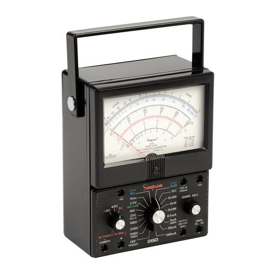
- Page 1 Simpson 260 Series 6XLM ® Volt-Ohm-Milliammeter INSTRUCTION MANUAL...
- Page 2 This warranty shall not apply to any instrument or other article of equipment which shall have been repaired or altered outside the SIMPSON ELECTRIC COMPANY factory or authorized service centers, nor which has been subject to misuse, neg- ligence or accident, incorrect wiring by others, or installation or use not in accord with instructions furnished by the manufacturer.
- Page 3 NOTES:...
-
Page 4: Table Of Contents
Contents INTRODUCTION ................7 1.1 General Description ................7 1.2 Test Leads ....................7 1.3 Accessories and Supplies ..............7 1.4 Technical Data ..................7 1.5 Definition of Accuracy ................9 1.6 Safety Considerations ................10 2. INSTALLATION ................10 2.1 Unpacking and Inspection .............. - Page 5 NOTES:...
- Page 6 NOTES:...
-
Page 7: Introduction
They are well suited to servicing, production, inspection and engineering applica- tions. The 260 uses the Simpson taut-band movement, which is self-shielding. The taut- band suspension provides a high degree of repeatability and is highly resistant to shock or vibration. - Page 8 AC VOLTAGE: Ranges (full scale): 2.5V, 10V, 25V, 100V, 250V, 500V and 1000V Accuracy: ±3% of full scale on all ranges Sensitivity: 5000 Frequency Response: See curve in Figure 4-1 OHMS CONVENTIONAL: Ranges: R X 1, R X 100, R X 1k and R X 10k Ohms Center: 6, 600, 6000 and 60k Max.
-
Page 9: Definition Of Accuracy
RATED CIRCUIT-TO -GROUND VOLTAGE* (FLOAT POTENTIAL): 1000V AC/DC (1500 V peak) maximum 10. READOUT: 4-1/2 inch, 50 μA (full scale) taut-band meter *Per ANSI C39.5, April 1974 - “The specified voltage with respect to ground which may be safely and continuously applied to the cir- cuits of an instrument.”... -
Page 10: Safety Considerations
Safety Considerations This Operator’s Manual contains cautions and warnings alerting the user to haz- ardous operating and servicing conditions. This information is flagged by CAU- TION or WARNING symbols throughout this publication, where applicable, and is defined on the inside front cover under NOTES AND SAFETY INFORMATION. Adhere to these instructions in order to ensure the safety of operating and servic- ing personnel and to retain the operating conditions of the Instrument. -
Page 11: Controls, Connectors & Indicators
CONTROLS, CONNECTORS & INDICATORS All operating and adjustment controls, connectors and indicators are described in this section along with a list (Table 3-1) describing their function. Become familiar with each item prior to operating the Instrument. Front Panel The 260 has a large, easy-to-read, 4-1/2” indicating instrument. Below the indi- cating instrument are three controls and seven circuit jacks. -
Page 12: Operation
Ohms Adjust: The ohms adjust control is a variable resistor in the ohm- meter circuit, which permits adjustment at infinity ( ) and at 0 for the low power and conventional ohms ranges, respec- tively. Circuit Jacks: There are seven jacks on the front panel marked with the functions they represent. -
Page 13: Adjust Pointer For Zero
Do not measure in a circuit where corona is present. Corona can be identi- fied by a pale blue color emanating from sharp metal points in the circuit, or by a buzzing sound, or by the odor of ozone. In rare instances, such as around germicidal lamps, ozone might be generated as a normal function. -
Page 14: Measuring Dc Voltage: 0-250 Mv
4.4.1 Measuring DC Voltage: 0-250 mV When using the Instrument as a millivoltmeter, care must be taken to prevent excessive voltage from damaging it. Before using the 250 millivolt range, first use the 1.0 volt DC range to affirm that the voltage measured is no greater than 250 millivolts. -
Page 15: Ac Voltage Measurement
4.5.1 Measuring AC Voltage NOTE: The Simpson 260-6XLM responds to the full-wave average value of an AC waveform. They are calibrated in terms of the RMS value of a pure sine wave. If the waveform is nonsinusoidal, the reading might be either higher or lower than the true RMS value, and could result in a substantial error. -
Page 16: Measuring Ac Voltage: 0-1000 V
have been discharged. Connect the test lead across the voltage source with the black lead on the ground side. Turn on the power in the circuit being measured and read the voltage on the red scale marked AC. For the 0-2.5V range, read the value directly on the red scale marked 2.5V AC. -
Page 17: Measuring Decibels
Set the range switch to one of the range positions marked 2.5V, 10V, 25V, 100V or 250V. Be sure the power is off in the circuit being measured. Connect the test leads across the circuit being measured with the black test lead to the ground side. -
Page 18: Measuring Direct Current: 0-50 Μa
Always turn the power off and discharge all the capacitors before resetting the switches or disconnecting the leads. Always connect the Instrument in series with the ground side of the circuit under measurement and never exceed the circuit to ground voltage (Table 1-1, item 7). 4.8.1 Measuring Direct Current: 0-50 μA Set the function switch to +DC. -
Page 19: Resistance Measurement
Resistance Measurement Before making resistance measurements, remove all power to the circuit under test. Discharge all capacitors. The 260 has six resistance ranges. Two are low power ohms and the other four are conventional ohm ranges powered by two batteries. The low power ohms ranges are used for accurate and safe measurements of resistance in semicon- ductor and integrated circuits. -
Page 20: Operating Servicing
4. Voltages as low as 30 volts rms or 42 4 volts peak can redner an electric shock 5. Read the Operator's Manual for additional precautions and instructions. MADE IN U.S.A. SIMPSON ELECTRIC COMPANY LAC DU FLAMBEAU, WI ADAPTOR LOCK To replace the D size battery 1. -
Page 21: Case Removal
and then gently push the + side of the battery into place. To replace the 9V battery 1.withdraw old battery and mating connector from the compartment. 2. Remove the connector from the old battery and connect it to new battery. 3. - Page 22 Verify Instrument accuracy by performing operational checks using known, accurate, stable sources. If proper calibration equipment is unavailable, con- tact your nearest Simpson Authorized Service Center. If the Instrument has not been used for 30 days, check the batteries for leakage and replace, if necessary.
- Page 23 NOTES:...
- Page 24 SIMPSON ELECTRIC COMPANY 520 Simpson Avenue Lac du Flambeau, WI 54538-0099 (715) 588-3311 FAX (715) 588-3326 Printed in U.S.A. Part No. 06-110935 Edition 15, 06/17 Visit us on the web at: www.simpsonelectric.com...
Need help?
Do you have a question about the 260-6XLM and is the answer not in the manual?
Questions and answers