Table of Contents
Advertisement
Quick Links
Advertisement
Table of Contents

Related Manuals for Pulsar PG7750BCO


Summary of Contents for Pulsar PG7750BCO
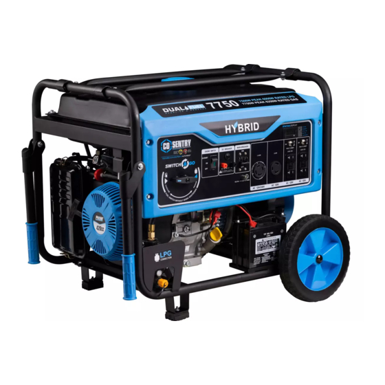
- Page 1 Model#: PG7750BCO Generator OPERATOR’S MANUAL support@pulsar-products.com...
-
Page 2: Table Of Contents
TABLE OF CONTENTS Introduction.....................................3 Product Specifications..............................3 Parts Ordering / Customer Service..........................3 Safety Rules.................................... 4 Safety Symbols................................4 Safety Instructions ..............................4 Features....................................7 Assembly ....................................9 Unpacking ..................................9 Packing List ................................9 Remove Shipping Bracket ............................10 Attaching Wheels ..............................10 Installing support leg ..............................10 Installing the handles ..............................11... -
Page 3: Introduction
INTRODUCTION Thank you for purchasing this superior quality portable generator from Pulsar P roducts Inc. When operating and maintaining this product as instructed in this manual, your generator will give you many years of reliable service. Product Specifications: This generator is an engine-driven, revolving field, alternating current (AC) portable generator. It is designed to supply electrical power to operate tools, appliances, camping equipment, lighting, or serve as a backup power source during power outages. -
Page 4: Safety Rules
SAFETY RULES Safety Symbols Indicates a potentially hazardous WARNING! situation which could result in serious injury or death if not avoided. Indicates a potentially hazardous CAUTION! situation which could result in damage to equipment or property. Toxic Fumes Risk of fire Risk of explosion Risk of electric shock Hot surface... - Page 5 SAFETY RULES Never exceed generator’s wattage / amperage capacity. This could damage the generator WARNING! and / or connected electrical devices. Check operating voltage and frequency of all electrical devices prior to plugging in to generator. • Never start or stop engine with electrical devices plugged in to the receptacles. Failure to do WARNING! so could damage the generator and/or connected electrical devices.
- Page 6 Never transport or make adjust this unit while it is running. • Never insert objects through cooling slots. Never operate this unit if there are any broken or missing parts and only use Pulsar WARNING! replacement parts specifically designed for this unit.
-
Page 7: Features
FEATURES A - ON/OFF Switch 12 Volt 8.3 Amp Output Hour Meter Fuel Selector Switch Protectors Main Breaker Four 120v GFCI outlets (NEMA 5-20) CO Sensor Light 120 Volt AC, 30 Amp twist lock receptacle (NEMA L5-30). 120 / 240 Volt AC, 30 Amp twist lock receptacle (NEMA L14-30). - Page 8 FEATURES K- Tank Vapor Valve R - Support Leg (Foot) S - Fuel Tank L - Fuel Gauge T - Fuel Fill Cap M - Generator Frame U - Fuel Valve (ON/OFF) N - Choke Lever V - Recoil Starter Grip O - Air Filter Housing W - Oil Fill (Dipstick) P - Handles &...
-
Page 9: Assembly
ASSEMBLY Unpacking 1. Place box on a level surface. 2. Remove all items from box except the generator. Make sure all items listed on the packing list are included and undamaged. 3. Cut-down the sides of the box being careful to avoid touching the generator. 4. -
Page 10: Remove Shipping Bracket
ASSEMBLY Attaching Wheels (See fig 1) • Parts needed - 2 wheels, 2 axles, 2 hair pins, and 2 washers. • Raise or tilt generator so you can slide the wheel axle pin into the wheel, the washer, the wheel mounting hole located on the side of the frame. -
Page 11: Installing The Handles
ASSEMBLY Attaching Battery Cable (See fig 3) • Locate the pigtail harness already attached to the battery (-) negative post • Ensure the hardware is tight and the red rubber boot is fitted over the (+) battery • connection Align the male and female battery cable connectors and firmly fit them together Be careful not to short across the terminals when installing. -
Page 12: Adding Oil/Checking Engine Oil
ASSEMBLY DANGER/POISON NON-SPILLABLE FLUSH EYES SEALED BATTERY IMMEDIATLEY WITH WATER This is a ready filled, SHIELD activated sealed battery. SULFURIC EYES. Never remove strip. EXPLOSIVE ACID MEDICAL SPARKS Refer to owner’s manual GASES CAN CAN CAUSE HELP FLAMES CAUSE BLINDNESS or instruction sheet for BLINDNESS OR FAST... -
Page 13: Adding Fuel
ASSEMBLY Adding Fuel (See fig 6) • Set generator outdoors in a well-ventilated area, away from structures and people. • Slowly remove fuel cap. • Insert a funnel into the fuel tank and carefully pour gasoline into the tank until fuel level reaches 1 ½ inches below the top of the neck. -
Page 14: Operation
OPERATION Grounding the Generator (See fig 7) The portable generator is equipped with a terminal for the connection of a ground electrode conductor where a grounding electrode system is required by NEC Article 250.34(A). The equipment grounding conductors of the generator receptacles are bonded to the generator frame. -
Page 15: How To Stop Engine
OPERATION Never start or stop engine with electrical devices plugged in to the receptacles. Failure to WARNING! heed this warning could damage the generator and / or connected electrical devices. • Always start the engine and let it stabilize before connecting any electrical devices. •... -
Page 16: Do Not Overload Generator
OPERATION 120 / 240 Volt AC, 30 Amp locking receptacle • This receptacle has a 30 Amp push-to reset circuit breaker to protect against overload. • This receptacle is rated to operate 120 Volt, AC, single phase, 60Hz loads requiring up to 3600 watts (3.6 kW) at 30 Amps. -
Page 17: Wattage Reference Guide
OPERATION Operating voltage and frequency requirement of all electrical equipment should be checked prior to plugging them into this generator. Damage may result if the equipment is not designed to operate within a +/- 10% voltage variation, and +/- 3 Hz frequency variation from the generator name plate ratings. -
Page 18: Cold Weather Operation
OPERATION Hour Meter (See Fig 19) Use this meter along with the manual to determine when and what type of service on the unit is needed. The display will show the word “LUBE” at the first 25 hours of operation and again at every 100 hours of operation after. Power Management Start engine without anything connected to generator. -
Page 19: Maintenance
MAINTENANCE Creating a Temporary Cold Weather Shelter In an emergency, the original shipping carton can be used as a temporary shelter. The shelter should hold enough heat created by the generator to prevent icing. Cut off all flaps. Cut off one of the long sides of the carton to expose the units muffler and exhaust. Do not enclose the muffler / exhaust side of the generator. -
Page 20: Changing Oil
MAINTENANCE Changing Oil (See Fig 21) • Run the Generator until the Engine is warm, then shut OFF. • Place generator on a level surface. • Remove the crankcase dipstick. • Place an oil pan underneath the oil drain hole to collect used oil. Oil Fill &... -
Page 21: Engine Maintenance
Spark Arrestor (See Fig 24) • Inspect the spark arrestor for breaks or holes. Replace if necessary. To purchase a replacement spark arrestor contact PULSAR customer service. • Use a brush to remove carbon deposits from the spark arrestor screen as needed. -
Page 22: Maintaining Fuel Valve
The effect of altitude on horsepower will be greater than this if no carburetor modification is made. Replacing Fuel Filter (See Fig 25 If Applicable) Occasionally the fuel filter may become clogged and need replacing. To purchase a replacement fuel filter contact PULSAR customer service or your local small Engine repair shop. -
Page 23: How To Store
MAINTENANCE Draining the carburetor • Turn the fuel valve to the OFF position. • Turn the engine OFF. • Position a suitable container under the carburetor drain screw to catch fuel; loosen and remove the screw. • Allow fuel to drain completely into container, be sure to wipe up any spilled fuel right away. •... -
Page 24: Troubleshooting
TROUBLESHOOTING Problem Cause Solution Engine is running, but AC output is not 1. Open circuit breaker 1. Reset circuit breaker available 2. Poor connection 2. Check and repair 3. Defective cord set 3. Check and repair 4. Connected device is faulty 4. - Page 25 The YELLOW light will flash for at least five minutes after a fault. The generator can be re-started, but may continue to shutoff. A CO sensor fault can only be diagnosed and repaired by an authorized Pulsar service center.
-
Page 26: Diagrams
DIAGRAMS...
Need help?
Do you have a question about the PG7750BCO and is the answer not in the manual?
Questions and answers
hour meter
The hour meter on the Pulsar PG7750BCO is used to track the total hours of operation. It helps determine when and what type of maintenance is needed. The display shows the word “LUBE” at the first 25 hours of operation and again at every 25-hour interval to indicate it is time for maintenance.
This answer is automatically generated