Table of Contents
Advertisement
www.nordictrack.com
USERʼS MANUAL
Model No. 831.24992.5
Serial No.
Write the serial number in the space
above for reference.
Serial Number
Decal
QUESTIONS?
If you have questions, or if parts are
damaged or missing, DO NOT CON-
TACT THE STORE; please contact
Customer Care.
IMPORTANT: Please register this
product (see the limited warranty
on the back cover of this manual)
before contacting Customer Care.
1-800-TO-BE-FIT
CALL TOLL-FREE:
(1-800-862-3348)
Mon.–Fri. 6 a.m.–6 p.m. MT
Sat. 8 a.m.–4 p.m. MT
ON THE WEB:
www.nordictrackservice.com
CAUTION
Read all precautions and instruc-
tions in this manual before using
this equipment. Save this manual
for future reference.
Advertisement
Table of Contents

Related Manuals for NordicTrack C 1500


Summary of Contents for NordicTrack C 1500
- Page 1 USERʼS MANUAL Model No. 831.24992.5 Serial No. Write the serial number in the space above for reference. Serial Number Decal QUESTIONS? If you have questions, or if parts are damaged or missing, DO NOT CON- TACT THE STORE; please contact Customer Care.
-
Page 2: Table Of Contents
Apply the decal in the location shown. Note: The decals may not be shown at actual size. NORDICTRACK is a registered trademark of ICON IP, Inc. -
Page 3: Important Precautions
14. To informed of all warnings and precautions. purchase a surge suppressor, see your local NORDICTRACK dealer, call the telephone 3. Use the treadmill only as described. number on the front cover of this manual, or see your local electronics store. - Page 4 20. Never leave the treadmill unattended while it 24. Inspect and properly tighten all parts of the is running. Always remove the key, unplug treadmill regularly. DANGER: the power cord, and press the power switch into the off position when the treadmill is not Always unplug the power in use.
-
Page 5: Before You Begin
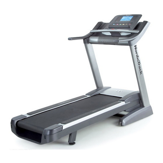
Thank you for selecting the revolutionary ing this manual, please see the front cover of this man- NORDICTRACK C 1500 treadmill. The C 1500 tread- ual. To help us assist you, please note the product ® mill offers an impressive selection of features designed model number and serial number before contacting us. -
Page 6: Part Identification Chart
PART IDENTIFICATION CHART Use the drawings below to identify small parts used for assembly. The number in parentheses below each draw- ing is the key number of the part, from the PART LIST near the end of this manual. The number following the key number is the quantity used for assembly. -
Page 7: Assembly
ASSEMBLY • Assembly requires two persons. • To identify small parts, see page 6. • Place all parts in a cleared area and remove the • Assembly requires the following tools: packing materials. Do not dispose of the packing materials until you finish assembly. the included hex key •... - Page 8 3. Identify the Left Upright (89), which is marked “Left.” Have a second person hold the Left Upright near the Base (97). See the inset drawing. Tie the wire tie in the Left Upright (89) securely around the end of the Wire Upright Wire (84).
- Page 9 5. Identify the Left and Right Base Covers (92, 93). Slide the Left Base Cover onto the Left Upright (89). Slide the Right Base Cover onto the Right Upright (90). Do not press the Base Covers into place yet. 6. With the help of a second person, hold the con- sole assembly near the Left Upright (89).
- Page 10 7. Insert the wires into the Left Upright (89) as you set the console assembly on the Left and Right Uprights (89, 90). Be careful not to pinch the Console Upright Wire (84). Assembly Attach the console assembly with four 5/16" x 1 1/2"...
-
Page 11: Have A Second Person Hold The Frame Until
9. Firmly tighten the four 3/8" x 2 3/4" Screws (7) first and then tighten the four 3/8" x 1 1/4" Screws (8) (only one side is shown). Press the Left and Right Base Covers (92, 93) onto the Base (97) until they snap into place. 10. - Page 12 11. Attach the upper end of the Storage Latch (53) to the Frame (56) with a 3/8" x 1 3/4" Bolt (6) and a 3/8" Nut (11). Note: It may be necessary to move the Frame back and forth to align the Storage Latch with the Frame.
-
Page 13: The Chest Heart Rate Monitor
THE CHEST HEART RATE MONITOR HOW TO PUT ON THE HEART RATE MONITOR • Do not expose the heart rate monitor to direct sunlight for extended periods of time; do not expose The heart rate it to temperatures above 122° F (50° C) or below 14° monitor consists of F (-10°... -
Page 14: Operation And Adjustment
OPERATION AND ADJUSTMENT HOW TO CONNECT THE POWER CORD nominal 120-volt circuit capable of carrying 15 or more amps. To avoid overloading the circuit, do Use a Surge Suppressor not plug other electrical devices, except for low- power devices such as cell phone chargers, into the surge suppressor or into an outlet on the same Your treadmill, like other electronic equipment, can be circuit. - Page 15 CONSOLE DIAGRAM Audio Jack FEATURES OF THE CONSOLE You can even listen to your favorite workout music or audio books with the consoleʼs stereo sound system The treadmill console offers an impressive array of while you exercise. features designed to make your workouts more effec- To turn on the power, see page 16.
- Page 16 HOW TO TURN ON THE POWER HOW TO USE THE MANUAL MODE IMPORTANT: If the treadmill has been exposed to 1. Insert the key into the console. cold temperatures, allow it to warm to room tem- perature before turning on the power. If you do not See HOW TO TURN ON THE POWER at the left.
- Page 17 4. Change the incline of the treadmill as desired. The My Trail tab will show a track that represents 1/4 mile (400 meters). As you exercise, the flash- To change the incline of the treadmill, press the ing rectangle will show your progress. The My Trail Incline increase or decrease button or one of the tab will also show the number of laps you numbered 1 Step Incline buttons.
- Page 18 6. Measure your heart rate if desired. Press the Manual fan button to select a fan Note: If you use the handgrip heart rate monitor speed or to turn off the and the chest heart rate monitor at the same fan.
- Page 19 HOW TO USE AN ONBOARD WORKOUT During the workout, the 1. Insert the key into the console. profiles on the speed and in- See HOW TO TURN ON THE POWER on page 16. cline tabs will Current Segment show your 2.
- Page 20 HOW TO USE AN IFIT LIVE WORKOUT If the speed or incline setting is too high or too low at any time during the workout, you can manually override the setting by pressing the Speed or Note: To use an iFit Live workout, you must have an Incline buttons;...
- Page 21 Press the iFit Live button to download the next the Speed increase button. The walking belt will workout in your schedule. Press the My Trainer begin to move at the speed setting for the first seg- button, the My Maps button, the World Tour button, ment of the workout.
-
Page 22: The Information Mode
THE INFORMATION MODE 3. CONTRAST LVL: Press the Incline increase and decrease buttons to adjust the contrast level of the The console features an information mode that keeps display. track of treadmill information and allows you to person- If a module is connected, you may also select the alize console settings. - Page 23 HOW TO USE THE STEREO SOUND SYSTEM Next, press the Play button Volume Increase on your MP3 player, CD To play music or audio books through the consoleʼs player, or other personal stereo speakers, you must connect your MP3 player, audio player.
-
Page 24: How To Fold And Move The Treadmill
HOW TO FOLD AND MOVE THE TREADMILL HOW TO FOLD THE TREADMILL HOW TO MOVE THE TREADMILL To avoid damaging the treadmill, adjust the incline Before moving the treadmill, fold it as described at the to 0 percent before you fold the treadmill. Then, re- left. -
Page 25: Troubleshooting
TROUBLESHOOTING Most treadmill problems can be solved by following SYMPTOM: The console displays remain lit when the simple steps below. Find the symptom that you remove the key from the console applies, and follow the steps listed. If further assis- tance is needed, see the front cover of this manual. - Page 26 SYMPTOM: The walking belt slows when walked on Lower the treadmill (see HOW TO LOWER THE TREADMILL FOR USE on page 24). Next, remove the three #8 x 3/4" Screws (1). Then, carefully pivot a. Use only a single-outlet surge suppressor that the Motor Hood (71) off.
- Page 27 SYMPTOM: The walking belt is off-center or slips b. If the walking belt slips when walked on, first re- when walked on move the key and UNPLUG THE POWER CORD. Using the hex key, turn both idler roller screws a. If the walking belt is off-center, first remove the clockwise, 1/4 of a turn.
-
Page 28: Exercise Guidelines
EXERCISE GUIDELINES WARNING: Burning Fat—To burn fat effectively, you must exer- cise at a low intensity level for a sustained period of Before beginning this time. During the first few minutes of exercise, your or any exercise program, consult your physi- body uses carbohydrate calories for energy. - Page 29 SUGGESTED STRETCHES The correct form for several basic stretches is shown at the right. Move slowly as you stretch—never bounce. 1. Toe Touch Stretch Stand with your knees bent slightly and slowly bend forward from your hips. Allow your back and shoulders to relax as you reach down toward your toes as far as possible.
-
Page 30: Part List
PART LIST Model No. 831.24992.5 R0212A Key No. Qty. Description Key No. Qty. Description #8 x 3/4" Screw Reed Switch Clamp 5/16" x 3 3/4" Screw Reed Switch 3/8" x 2" Bolt Storage Latch 5/16" x 2" Screw Drive Motor 5/16"... - Page 31 Key No. Qty. Description Key No. Qty. Description Wheel Pulse Ground Wire Console Base Pulse Bar Bottom Console 1/2" Rear Leveling Foot Nut Console Back 3/8" Flat Washer Fan Assembly Short Hex Key Handrail Spacer #8 x 3/8” Screw Console Frame –...
-
Page 32: Exploded Drawing
EXPLODED DRAWING A Model No. 831.24992.5 R0212A... - Page 33 EXPLODED DRAWING B Model No. 831.24992.5 R0212A...
- Page 34 EXPLODED DRAWING C Model No. 831.24992.5 R0212A...
- Page 35 EXPLODED DRAWING D Model No. 831.24992.5 R0212A...
-
Page 36: Ordering Replacement Parts
ORDERING REPLACEMENT PARTS To order replacement parts, please see the front cover of this manual. To help us assist you, be prepared to pro- vide the following information when contacting us: • the model number and serial number of the product (see the front cover of this manual) •...
Need help?
Do you have a question about the C 1500 and is the answer not in the manual?
Questions and answers