
Related Manuals for Wacker Neuson GPS 8500


Summary of Contents for Wacker Neuson GPS 8500
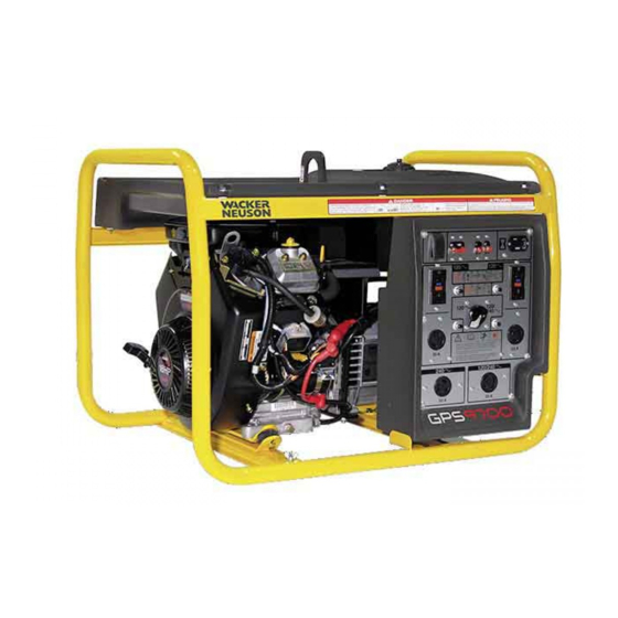
- Page 1 0176674en 0809 Generator, Non-CARB GPS 8500 GPS 9700 OPERATOR’S MANUAL...
-
Page 2: Carbon Monoxide
DANGER CARBON MONOXIDE Using a generator indoors CAN KILL YOU IN MINUTES. Generator exhaust contains carbon monoxide (CO). This is a poison you cannot see or smell. If you can smell the generator exhaust, you are breathing CO. But even if you cannot smell the exhaust, you could be breathing CO. -
Page 3: Foreword
Foreword This manual provides information and procedures to safely operate and maintain this Wacker Neuson model. For your own safety and protection from injury, carefully read, understand and observe the safety instructions described in this manual. Keep this manual or a copy of it with the machine. If you lose this manual or need an additional copy, please contact Wacker Neuson Corporation. - Page 4 wc_tx001035gb.fm...
-
Page 5: Table Of Contents
GPS 8500 / GPS 9700 Table of Contents Foreword Safety Information Laws Pertaining to Spark Arresters ............7 Operating Safety .................. 8 Operator Safety while using Internal Combustion Engines ....9 Service Safety ..................10 Label Locations .................. 11 Safety and Operating Labels .............. 12 Operation Application and Power Requirements .......... - Page 6 Table of Contents GPS 8500 / GPS 9700 Maintenance Engine Maintenance ................28 Periodic Maintenance Schedule ............28 Engine Lubrication ................29 Oil Filter ....................30 Air Cleaner ..................31 Spark Plug ...................32 Fuel Filter ....................33 Carburetor Adjustment ................34 Storage ....................35 3.10 Transporting ..................36 3.11 Troubleshooting ...................37...
-
Page 7: Safety Information
GPS 8500 / GPS 9700 Safety Information Safety Information This manual contains DANGER, WARNING, CAUTION, NOTICE and NOTE callouts which must be followed to reduce the possibility of personal injury, damage to the equipment, or improper service. This is the safety alert symbol. It is used to alert you to potential personal injury hazards. -
Page 8: Operating Safety
Safety Information GPS 8500 / GPS 9700 Operating Safety BACKFEED FROM THE GENERATOR INTO THE PUBLIC POWER DISTRIBUTION SYSTEM CAN CAUSE SERIOUS INJURY OR DEATH TO UTILITY WORKERS! DANGER Improper connection of generator to a building’s electrical system can allow electrical current from the generator to backfeed into utility lines. -
Page 9: Operator Safety While Using Internal Combustion Engines
GPS 8500 / GPS 9700 Safety Information 1.2.11 ALWAYS transport the generator in an upright position. 1.2.12 ALWAYS keep the machine at least one meter (three feet) away from structures, buildings, and other equipment during use. 1.2.13 ALWAYS keep the area immediately surrounding and underneath the machine clean, neat, and free of debris and combustible materials. -
Page 10: Service Safety
Safety Information GPS 8500 / GPS 9700 Service Safety Poorly maintained equipment can become a safety hazard! In order for the equipment to operate safely and properly over a long period of time, periodic maintenance and occasional repairs are necessary. If... -
Page 11: Label Locations
GPS 8500 / GPS 9700 Safety Information Label Locations... -
Page 12: Safety And Operating Labels
Safety Information GPS 8500 / GPS 9700 Safety and Operating Labels Wacker Neuson machines use international pictorial labels where needed. These labels are described below: Label Meaning DANGER GEFAHR STOP PELIGRO DANGER DANGER! Engines emit carbon monoxide; operate only in well-ventilated area. Read the Operator’s Manual. -
Page 13: Safety Information
GPS 8500 / GPS 9700 Safety Information Label Meaning Neutral bonded to frame. Key switch: start Open main circuit breaker. Open the fuel flow valve. Open the choke. Turn engine key switch to “ON” position. - Page 14 Safety Information GPS 8500 / GPS 9700 Label Meaning Pull rewind starter or turn engine key switch to crank starter. Close main circuit breaker. Close the fuel flow valve. Close the choke. Turn engine key switch to “OFF” position. I, J Using a generator indoors CAN KILL YOU IN MINUTES.
- Page 15 GPS 8500 / GPS 9700 Safety Information Label Meaning Only use OUTSIDE and far away from windows, doors, and vents. This equipment does not meet Califor- nia EVP emission regulations for small off-road engines. Improper connection of generator to a building’s electrical system can allow...
-
Page 16: Operation
Operation GPS 8500 / GPS 9700 Operation Application and Power Requirements This generator is designed to operate single-phase, 60 Hz appliances running at 120 and 240 VAC. NOTICE: Do not exceed the continuous rated output of the generator. Damage to tools or generator will occur. See Technical Data. -
Page 17: Installation
GPS 8500 / GPS 9700 Operation Installation Place the generator in an area where it will not be exposed to rain, snow, or direct sunlight. Make sure it is positioned on firm, level ground, so it will not slide or shift. Position the engine exhaust away from areas where people may be present. -
Page 18: Generator Derating
Operation GPS 8500 / GPS 9700 Generator Derating All generators are subject to derating for altitude and temperature. Internal combustion engines, unless modified, run less efficiently at higher altitudes due to the reduction of air pressure. This translates into a lack of power and thus reduction in generator output. -
Page 19: Grounding The Generator
GPS 8500 / GPS 9700 Operation Grounding the Generator A ground connection (a) is located on the generator frame. For proper operating safety, this ground terminal must be connected to a good ground source. This ground connection must comply with National Electrical Code standards, and state and local regulations. -
Page 20: Use Of Extension Cords
Operation GPS 8500 / GPS 9700 Use of Extension Cords When a long extension cord is used to connect an appliance or tool to the generator, a voltage loss occurs—the longer the cord, the greater the voltage loss. This results in less voltage being supplied to the appliance or tool and increases the amount of current draw or reduces performance. -
Page 21: Control Panel
GPS 8500 / GPS 9700 Operation Control Panel Ref. Description Ref. Description Auto Idle Switch Thermal Overload Main Circuit Breaker Voltage Selector Switch 240V 20A Overcurrent Circuit 120V 30A Twist-lock Receptacle Breaker 120/240V 30A Overcurrent Circuit 120V 20A Twist-lock Receptacle... -
Page 22: Main Circuit Breaker
Operation GPS 8500 / GPS 9700 Main Circuit Breaker The generator is protected by a main breaker (b) located on the control panel. The circuit breaker protects the generator from severe overloads or short circuits. If the circuit breaker opens, turn the engine off immediately and determine the cause before restarting. -
Page 23: Voltage Selection
GPS 8500 / GPS 9700 Operation 2.10 Voltage Selection The voltage selector switch (h) allows the generator to operate in either single (120V) or dual voltage (120/240V) mode. In single voltage mode only the 120V twist lock and 120V duplex receptacles are powered. -
Page 24: Engine Auto Idle
Operation GPS 8500 / GPS 9700 2.12 Engine Auto Idle The auto idle switch (a) automatically reduces engine speed 5 seconds after all appliances or tools attached to the generator have been turned off. Engine automatically returns to full speed when a tool or appliance is turned back on. -
Page 25: Before Starting
GPS 8500 / GPS 9700 Operation 2.14 Before Starting 2.14.1 Read and understand safety and operating instructions at beginning of this manual. 2.14.2 Read and understand the meanings of all warning and operating labels. 2.14.3 Make sure that a battery has been installed. See Recommended Battery. -
Page 26: To Stop
Operation GPS 8500 / GPS 9700 2.15.5 Push choke in as engine warms (a2). 2.15.6 Place main circuit breaker in closed (l) position and place auto idle switch in ON (l) position. Allow engine to warm up and check function of GFI circuit breakers before attaching loads to generator (see Ground Fault Circuit Interrupt). - Page 27 GPS 8500 / GPS 9700 Operation Notes:...
-
Page 28: Maintenance
Maintenance GPS 8500 / GPS 9700 Maintenance Engine Maintenance The chart below lists basic machine and engine maintenance. Refer to your engine operator’s manual for additional information on engine maintenance. Periodic Maintenance Schedule Daily After Every Every Every before first... -
Page 29: Engine Lubrication
GPS 8500 / GPS 9700 Maintenance Engine Lubrication Check engine oil level daily, before starting engine. Add oil as required. To check oil level: 3.3.1 Place generator on a level surface. Clean area around oil fill and remove dipstick. 3.3.2 Pour oil (a) slowly, checking oil level occasionally with dipstick. -
Page 30: Oil Filter
Maintenance GPS 8500 / GPS 9700 Oil Filter Replace oil filter every 100 hours of operation. 3.4.1 Drain engine oil and replace with fresh oil before removing used oil filter. Note: In the interests of environmental protection, place a plastic sheet and a container under the machine to collect any liquid which drains off. -
Page 31: Air Cleaner
GPS 8500 / GPS 9700 Maintenance Air Cleaner Service air cleaner frequently to prevent carburetor malfunction. NOTICE: NEVER run engine without air cleaner. Severe engine damage will occur. NEVER use gasoline or other types of low flash point solvents for cleaning the air cleaner. -
Page 32: Spark Plug
Maintenance GPS 8500 / GPS 9700 Spark Plug Clean or replace the spark plug as needed to ensure proper operation. Refer to your engine operator’s manual. The muffler becomes very hot during operation and remains hot for a while after stopping the engine. Do not touch the muffler while it is hot. -
Page 33: Fuel Filter
GPS 8500 / GPS 9700 Maintenance Fuel Filter Check fuel lines and fittings daily for cracks or leaks. Replace as needed. Change in-line fuel filter (a) once a year. Allow engine to cool, and close fuel valve before replacing fuel filter. -
Page 34: Carburetor Adjustment
Maintenance GPS 8500 / GPS 9700 Carburetor Adjustment Note: Air cleaner must be in place and engine warm when making adjustments to carburetor. Only minor adjustments to carburetor are possible. Adjust mixture screw (b) between limits to obtain best acceleration from idle to full speed. -
Page 35: Storage
GPS 8500 / GPS 9700 Maintenance Storage Before storing generator for a long period of time: 3.9.1 Change the engine oil. 3.9.2 Disconnect the fuel line from the carburetor. Place open end of fuel line into a suitable container and open fuel valve to drain fuel from tank. -
Page 36: Transporting
Maintenance GPS 8500 / GPS 9700 3.10 Transporting Let the engine cool before transporting the generator or storing it indoors, to avoid burns or fire hazards. WARNING When transporting the generator: 3.10.1 Turn the engine fuel valve to the OFF position. -
Page 37: Troubleshooting
GPS 8500 / GPS 9700 Maintenance 3.11 Troubleshooting Before ordering repairs, carefully read through this manual, then repeat the inspection. If the problem remains, contact your nearest dealer or Wacker representative. Problem / Symptom Reason / Remedy If engine doesn't start, check •... -
Page 38: Generator Wiring Schematic
Maintenance GPS 8500 / GPS 9700 3.13 Generator Wiring Schematic... - Page 39 GPS 8500 / GPS 9700 Maintenance Ref. Description Ref. Description Ref. Description Generator Control box Engine Ref. Description Ref. Description Main stator winding Choke Transformer Hour meter Auto Voltage Regulator (AVR) Engine module Resistor (GPS 9700 only) Oil level switch...
-
Page 40: Engine Wiring Diagram
Maintenance GPS 8500 / GPS 9700 3.14 Engine Wiring Diagram Ref. Description Ref. Description Carburetor solenoid Regulator rectifier Stop switch terminal DC output wire 50 Hz. loop Key switch (GPS 8500=yellow, GPS 9700=red) Module Solenoid Idle down device Battery terminal... -
Page 41: Technical Data
GPS 8500 / GPS 9700 Technical Data Technical Data Generator Item No. GPS 8500 GPS 9700 Generator Maximum Output 8.5 / 8.5 9.7 / 9.7 kW / kVA Continuous Output Type Dual voltage, single phase, brush-type system AC Voltages Available... -
Page 42: Engine
Technical Data GPS 8500 / GPS 9700 Engine Engine power rating Gross power rating per SAE J1995. Actual power output may vary due to conditions of specific use. Item No. GPS 8500 GPS 9700 Engine Engine type 2 cylinder, 4-cycle,... - Page 44 Fax: +49 - (0)89-3 54 02-3 90 Wacker Neuson Corporation · P.O. Box 9007 · Menomonee Falls, WI 53052-9007 · Tel. : (262) 255-0500 · Fax: (262) 255-0550 · Tel. : (800) 770-0957 Wacker Asia Pacific Operations · Skyline Tower, Suite 2303, 23/F · 39 Wang Kwong Road, Kowloon Bay, Hong Kong · Tel. +852 2406 60 32 · Fax: +852 2406 60 21...
Need help?
Do you have a question about the GPS 8500 and is the answer not in the manual?
Questions and answers