
Related Manuals for GMP EXCELMASTER-1600


Summary of Contents for GMP EXCELMASTER-1600
-
Page 1: Cover
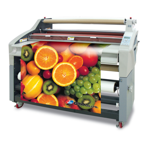
USER'S GUIDE EXCELMASTER-1600 Before operating the unit, please read this manual thoroughly and retain it for future reference. -
Page 2: Table Of Contents
TABLE OF CONTENT Film Loading and Threading Cover Load a Roll of Film Loading Top Thermal Film Loading Top PSA Film Loading Top Mount Adhesive Loading Bottom Thermal Film Table of Content Loading Bottom PSA Film Loading Bottom Mount Adhesive Important Safety Instructions Threading Card Procedure Start Laminating... -
Page 3: Important Safety Instructions
Keep hands and fingers away from the path of the UPON THIS PRODUCT. are unauthorized and shall not be binding upon sharp film cutter blade located at the film exit. GMP. In no event shall GMP be liable for any ADVERTENCIA ATTENTION WARNING... -
Page 4: Specifications
SPECIFICATIONS - EXCELMASTER-1600 Operating Speed: Up to 5 m/min Temperature range: 211 cm C - 150 Max. Mounting Thickness: 1.3 cm Max. Film Width: 131 cm EXCELMASTER : 165 cm Dimensions (W x D x H): 102 cm Unit alone: (Figure 2) -
Page 5: Pre-Installation
PRE-INSTALLATION Before a Laminator can be installed, ensure the following requirements are met; 1. Are door ways and hallways wide enough for the laminator to be moved to the installation site? 101.6 x 152 cm 2. Is there ample room for the 220 cm Work table on wheels laminator? -
Page 6: Installation
INSTALLATION 1. Shipping damage should be brought to the immediate attention of the delivering carrier. 2. With assistance, carefully roll the laminator into position over flat and even surfaces. 3. The laminator should be positioned to allow exiting film to flow freely to the floor or a work table (Figure 4). -
Page 7: Control Guide
CONTROL GUIDE Located at the back left of the machine applies power to the laminator. The control panel display will illuminate when position marked “l” is pushed. The off position, marked “O”, removes power from the laminator. B. CONTROL PANEL DISPLAY: (Figure 4) Illuminates when the laminator is plugged in and POWER ON/ OFF is in the on, (I), position. -
Page 8: Rewinder Selection Switch
Press/ Release : When pressed, raises the upper main roller over riding the pull roller handle setting. When pressed again, reverts to current pull roller handle setting. Cooling : (Figure 7) When pressed, turns on the cooling fans. When pressed again, turns off the cooling fans. -
Page 9: Upper Rewinder Direction Switch
E. UPPER REWINDER DIRECTION SWITCH: (Figure 9) This switch enables the operator to control the REWINDER FWD. direction of the upper rewind/ FWD. unwind shafts. STOP REV. “FWD.” : In this position, the motor REV. REV. runs in a forward direction. “STOP”... -
Page 10: Features Guide
FEATURES GUIDE A. E-STOP: (Figure 12) Two E- STOP buttons exist on the laminator. One on each side of the upper cabinet. To engage (1), press either push button, roller movement is stopped. To disengage (2), turn the push button clockwise once the emergency condition has been resolved. -
Page 11: Roller Handle
G. ROLLER HANDLE: (Figure 15) The roller handle manually sets the position of the pull rollers while simultaneously electronically setting the main rollers. Available settings are; – Release 15mm Mounting – 15mm Mounting 10mm Mounting Release – 10mm Mounting 5mm Mounting –... -
Page 12: Rewind Shaft
(Figure 18) Required if running Micronext® material. To install, replace the rear slitter with the separator bar. Y. REWIND KIT OPTION: Enables roll to roll webbing of material. This kit must be installed by a qualified GMP service representative. Fig. 20... -
Page 13: Film Loading And Threading
(matte) film as both sides appear dull. Always change the top and bottom supply rolls at the same time. Near the end of each roll of GMP laminating film is a label stating Polyester surface “Warning-End of Roll”. The appear- ance of this label on either the top or Fig. -
Page 14: Loading Top Thermal Film
LOADING TOP THERMAL FILM This procedure describes how to load the upper roll of film onto the laminator. Figure 23 uses poly-in film and the upper rear unwind/ rewind position for illustration purpose. 1. Turn the Power ON/OFF to on (I). -
Page 15: Loading Top Mount Adhesive
LOADING TOP MOUNT ADHESIVE This procedure describes how to load a roll of mount adhesive using the upper position for pre-coating (Figure 25). 1. Turn the Power ON/OFF to on (I). If the laminator is already hot, turn POWER ON/OFF to the off (O) position and allow the unit to cool. -
Page 16: Loading Bottom Psa Film
LOADING BOTTOM PSA FILM This procedure describes how to load a roll of mount adhesive using the lower unwind position for decaling (Figure 27). 1. At this point you should have an upper roll of PSA film loaded onto the laminator. 2. -
Page 17: Threading Card Procedure
THREADING CARD PROCEDURE This procedure describes how to feed two loaded films through the main rollers (Figure 29). 1. At this point you should have an Threading card upper roll of film and lower roller roll of film loaded onto the laminator with the appropriate material for your application. -
Page 18: Start Laminating
START LAMINATING 1. The safety shield and feed table must be in the normal operating position. 2. Select a job mode ( ) and ensure the proper speed and temperatures are set. Refer to the section entitled SPEED/ TEMPERATURE GUIDE. 3. -
Page 19: Tacking New Film To Existing Film
METHOD FOR TACKING NEW FILM TO EXISTING FILM The following describes a method for loading film whereby the Cut here existing film present on the heat rollers may be used in place of the threading card to draw the new film through the laminator. -
Page 20: To Unweb The Laminator
TO UNWEB THE LAMINATOR Unweb the laminator if you are changing film widths, cleaning the rollers or have finished using the Cut web machine for the day. 1. Using the rear slitter, cut the output from the web (Figure 34). Cut web 2. -
Page 21: Applications
APPLICATIONS TIPS FOR PRE-COATING BOARDS (Figure 36) Mount adhesive 1. Load the laminator as illustrated in Figure 36. Board 2. Ensure the chill idler is in the rest Leader board Trailer board position. 3. Set the roller pressure handle to the correct thickness. -
Page 22: Single Sided Lamination
TIPS FOR SINGLE SIDED LAMINA- TION (Figure 39) Roll 1. Load the laminator as illustrated of film If using PSA Film in Figure 39. 2. Use kraft paper for one-sided Image lamination whenever the items to be laminated are narrower than the film you are using. -
Page 23: Psa Encapsulation
TIPS FOR PSA ENCAPSULATION (Figure 42) Roll of PSA 1. Load the laminator as illustrated Film in Figure 42. 2. Always use two rolls of the Image same width. 3. Use minimal brake tension to achieve flat output. 4. The separation of the laminate and the release liner should be maintained close to the heat rollers. -
Page 24: The Art Of Lamination
THE ART OF LAMINATION BASIC RULES Do not attempt to laminate abrasive or metal objects such as staples, paper clips and glitter, as they may damage the heat or pull rollers. Do not force items into the nip area of the heat rollers. -
Page 25: Heat
HEAT The “WAIT (Too COLD)” indicator may appear if the speed is set too fast for the material being laminated. Either lower the speed setting or press STOP and wait until the “READY” indicator appears. Operation of the laminator for more than thirty minutes at a time may necessitate a lower speed setting. -
Page 26: Maintenance
MAINTENANCE CARING FOR THE EXCELMASTER-1600 LAMINATOR GMP offers Cleaning kits as well as Extended Maintenance Agreements. Contact your local GMP Service Representative or your dealer/distributor for additional informa- tion. The only maintenance required by the operator is to periodically clean the heat rollers and schedule semi annual maintenance checks. -
Page 27: Troubleshooting Guide
TROUBLESHOOTING GUIDE SYMPTOM POSSIBLE CAUSE CORRECTIVE ACTION • The control panel display does not Laminator not connected to Insert attachment plug into receptacle. illuminate when POWER ON/OFF is electrical supply. in the ON, marked “I”, position. • Heat rollers do not turn when I Safety shield is not properly Remove safety shield and properly replace it.
Need help?
Do you have a question about the EXCELMASTER-1600 and is the answer not in the manual?
Questions and answers