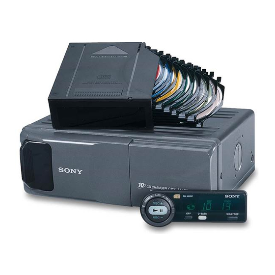
Sony CDX-444RF Service Manual
Compact disc charger system
Hide thumbs
Also See for CDX-444RF:
- Operating instructions manual (100 pages) ,
- Operating instructions (5 pages) ,
- Installation (4 pages)
Table of Contents
Advertisement
Quick Links
QQ
3 7 63 1515 0
SERVICE MANUAL
Ver 1.1 2001.06
TE
L 13942296513
CD changer (CDX-444RF)
System
Laser Diode Properties
Material
Wavelength
Emission Duration
Laser output power
* This output is the value measured at a distance of 200 mm from the
objective lens surface on the Optical Pick-up Block.
Transmitting frequency
Input/output terminals
Current drain
Operating temperature
Dimensions
Mass
www
.
Sony Corporation
9-870-222-12
2001F0500-1
e Vehicle Company
C 2001.6
Shinagawa Tec Service Manual Production Group
http://www.xiaoyu163.com
Compact disc digital audio system
GaAlAs
780 nm
Continuous
Less than 44.6 µW*
88.3 MHz/88.5 MHz/
88.7 MHz/88.9 MHz/
89.1 MHz/89.3 MHz/
89.5 MHz/89.7 MHz/
89.9 MHz (switchable)
Wired remote control (8 pin)
RF signal (FM) output
Power input (3 pin)
800 mA (at playback)
800 mA (at disc loading/ejecting)
–10°C to +55°C
(14°F to 131°F)
Approx. 262 × 90 × 181.5 mm
× 3
× 7
3
5
1
(10
/
/
/
in.) (w/h/d)
8
8
4
Approx. 2.1 kg (4 lb. 10 oz.)
x
ao
u163
y
i
http://www.xiaoyu163.com
CDX-444RF
2 9
8
Model Name Using Similar Mechanism
CD Drive Mechanism Type
Optical Pick-up Name
SPECIFICATIONS
Q Q
3
6 7
1 3
1 5
Relay box
Input/output
Dimensions
Mass
Wired remote (RM-X82RF)
Dimensions
Mass
Supplied accessories
Design and specifications are subject to change without notice.
COMPACT DISC CHANGER SYSTEM
co
.
9 4
2 8
US Model
Canadian Model
AEP Model
UK Model
E Model
CDX-434RF
MG-251A-137
KSS-720A
0 5
8
2 9
9 4
2 8
Antenna input terminal
Antenna output cord
CD Changer input cord
Approx. 40 × 40 × 27 mm
× 1
× 1
5
5
1
(1
/
/
/
in.) (w/h/d)
8
8
8
140 g (5 oz.)
Approx. 122 × 36.5 × 15.5 mm
× 1
×
(4
7
/
7
/
5
/
in.) (w/h/d)
8
16
8
Approx. 255 g (9 oz.)
Disc magazine (1)
Parts for installation and connections (1 set)
m
9 9
9 9
Advertisement
Table of Contents

Related Manuals for Sony CDX-444RF


Summary of Contents for Sony CDX-444RF
- Page 1 Model Name Using Similar Mechanism CDX-434RF CD Drive Mechanism Type MG-251A-137 Optical Pick-up Name KSS-720A SPECIFICATIONS L 13942296513 CD changer (CDX-444RF) Relay box System Compact disc digital audio system Input/output Antenna input terminal Laser Diode Properties Antenna output cord Material...
-
Page 2: Servicing Notes
SUR LES DIAGRAMMES SCHÉMATIQUES ET LA LISTE sub assy. DES PIÈCES SONT CRITIQUES POUR LA SÉCURITÉ DE FONCTIONNEMENT. NE REMPLACER CES COM- POSANTS QUE PAR DES PIÈCES SONY DONT LES NUMÉROS SONT DONNÉS DANS CE MANUEL OU DANS LES SUPPLÉMENTS PUBLIÉS PAR SONY. http://www.xiaoyu163.com... -
Page 3: Table Of Contents
http://www.xiaoyu163.com 3 7 63 1515 0 TABLE OF CONTENTS SERVICING NOTES ............2 GENERAL Location and Function of controls ........4 Installation ............... 8 Connections ..............9 DISASSEMBLY ............10 MECHANISM DECK ASSEMBLY ....16 MECHANICAL ADJUSTMENTS ....... 18 ELECTRICAL CHECK .......... -
Page 4: General
http://www.xiaoyu163.com SECTION 1 This section is extracted from instruction manual. GENERAL 3 7 63 1515 0 Location and function of controls Nomenclature Wired remote (RM-X82RF)/Télécommande à fil (RM-X82RF) 1 DISC (disc select) buttons 8 MHz (frequency) indication 1 Touches DISC (sélection de disques) 8 Indication MHz (fréquence) 9 u (play/pause) button 9 Touche u (lecture/pause) - Page 5 Face imprimée vers le haut Avec le côté portant la flèche orienté • To listen to an 8 cm (3 in.) CD, use the optional Sony CD adaptor vers le haut CSA-8. Be sure to always use the specified adaptor, as failing to do so may cause a malfunction of the unit.
- Page 6 http://www.xiaoyu163.com 3 7 63 1515 0 Operation Fonctionnement Precautions Précautions •This unit cannot be used with a car audio without an FM tuner. •Cet appareil ne peut être utilisé avec un autoradio sans syntoniseur FM. •If your car was parked in direct sunlight resulting in a considerable rise in temperature inside the car, •Si votre voiture est parquée en plein soleil, provoquant ainsi une augmentation considérable de la allow the unit to cool off before operating it.
- Page 7 http://www.xiaoyu163.com 3 7 63 1515 0 Press repeatedly to select Appuyez plusieurs fois de suite sur the output level. Changement du niveau de sortie pour sélectionner le niveau de Changing the output level sortie. To decrease the output level You can select the output level from the unit. Vous pouvez sélectionner le niveau de sortie de Pour diminuer le niveau de sortie Normally the unit is used at the initial output...
-
Page 8: Installation
http://www.xiaoyu163.com 3 7 63 1515 0 Installation Installation How to install the CD changer Installation du changeur de CD •When you install the CD changer, be careful not to damage wiring or equipment on the other side of the •Quand vous installez le changeur de CD, veillez à ne pas endommager les câbles ou les instruments qui mounting surface. -
Page 9: Connections
http://www.xiaoyu163.com 3 7 63 1515 0 Connections Connexions Caution Précautions •This unit is designed for negative ground 12 V •Be sure to connect the red power input lead •Cet appareil est uniquement conçu pour •Veillez à ne pas raccorder le fil rouge d‘entrée DC operation only. -
Page 10: Disassembly
http://www.xiaoyu163.com SECTION 2 DISASSEMBLY 3 7 63 1515 0 Note: Follow the disassembly procedure in the numerical order given. CASE (UPPER. T), FRONT PANEL ASSY 3 screw (PTT2.6 × 6) 3 screw (PTT2.6 × 6) 4 lever (FLT) 5 case (upper. T) 3 screw (PTT2.6 ×... - Page 11 http://www.xiaoyu163.com 3 7 63 1515 0 FM BOARD 2 screw 4 cover (FM) (ground) 1 screw (BVTT2.6 × 6) 5 FM board 3 cover (FM connector.T) L 13942296513 MAIN BOARD, SLIDE VARIABLE RESISTOR (ELEVATOR HEIGHT SENSOR) (RV202) 1 main flexible board (CNJ101) 5 two screws (FP) 6 screw...
- Page 12 http://www.xiaoyu163.com 3 7 63 1515 0 ELJ MOTOR ASSY (ELEVATOR) (M104) 1 screw (PTT2 × 4) 2 bracket (EVM.S) 3 ELJ motor assy (elevator) (M104) L 13942296513 ESCUTCHEON (T) 3 two claws 2 Remove the claw in the direction of arrow A . 4 Remove the ditch in the direction of arrow B .
- Page 13 http://www.xiaoyu163.com 3 7 63 1515 0 CHASSIS (U.S) SUB ASSY 2 Remove the edge in the direction 1 three screws of arrow A . (PTT2 × 4) 1 two screws (PTT2 × 4) 5 chassis (U.S) sub assy 1 screw (PTT2 ×...
- Page 14 http://www.xiaoyu163.com 3 7 63 1515 0 RF BOARD 3 two screws (PS2 × 4) 4 RF board 3 two screws (PS2 × 4) 2 Remove four solders of the LSW board leads and spindle motor leads (M102). 2 Remove two solders L 13942296513 of the sled motor leads 1 OP flexible board (CN102).
- Page 15 http://www.xiaoyu163.com 3 7 63 1515 0 LSW BOARD, SPINDLE MOTOR (S) SUB ASSY (M102) 8 two precision screws (P1.7 × 2.2) 3 spring (chucking) 6 retainer (disc) 1 precision screw (P2 × 2.5) 4 precision screw (P2 × 2.2) 5 bracket (CP) 2 LSW board 9 Remove the spindle motor (S) sub assy (M102) in the direction of the arrow.
-
Page 16: Mechanism Deck Assembly
http://www.xiaoyu163.com SECTION 3 MECHANISM DECK ASSEMBLY 3 7 63 1515 0 Note: Follow the assembly procedure in the numerical order given. OPTICAL PICK-UP COMPLETE ASSY 1 Move the lever (LOCK 3A) in the direction of arrow A , and return it a little in the direction of arrow B from the position where the chuck plate is moved chuck plate down to the lower limit. - Page 17 http://www.xiaoyu163.com 3 7 63 1515 0 OPERATION CHECK 1 Confirm that the slider moves in the direction of arrow C to move down the chuck plate if the gear (LOAD CAM) is rotated in the direction of arrow A or the chuck plate moves up and the slider moves in the direction of arrow D if the gear is rotated in the direction of arrow B .
-
Page 18: Mechanical Adjustments
http://www.xiaoyu163.com SECTION 4 MECHANICAL ADJUSTMENTS 3 7 63 1515 0 • Elevator Height (Address) Adjustment Adjustment Method: Note: This adjustments is necessary when the system controller (IC201), variable resistor (RV201), slider (R), slider (L), or chassis (ELV) 1. Load a disc magazine, and place the set vertically as shown was replaced for any repair. -
Page 19: Electrical Check
http://www.xiaoyu163.com SECTION 5 ELECTRICAL CHECK 3 7 63 1515 0 Note: FOCUS BIAS CHECK 1. This adjustment is performed with the set placed horizontally. 2. Power supply voltage: DC14.4 V (more than 3 A). Connection: 3. Be sure to use the disc “YEDS-18” parts code: 3-702-101-01, but only –... - Page 20 http://www.xiaoyu163.com 3 7 63 1515 0 TRACKING OFFSET CHECK Connection: – RF BOARD (Component Side) – oscilloscope (DC range) – TP (VC) IC101 TP (TE) Procedure: L 13942296513 1. Connect the oscilloscope to TP (TE) and TP (VC) on the RF board.
-
Page 21: Diagrams
CDX-444RF SECTION 6 3 7 6 3 1 5 1 5 0 DIAGRAMS 6-1. BLOCK DIAGRAM – SERVO Section – FILTER 63 66 65 RF AMP, FOCUS/TRACKING ERROR AMP EMPHI IC101 AOUT1 AIN1 LOUT L, R DETECTOR SERIAL PCMD... -
Page 22: Block Diagram - Main Section
CDX-444RF 3 7 6 3 1 5 1 5 0 6-2. BLOCK DIAGRAM – MAIN Section – IC701 RV702 DEVIATION CN703 L, R L IN GAMMA BUFFER BUFFER Q701 OUTPUT RF AMP (Page 21) Q702, 703 R IN GAMMA... -
Page 23: Note For Printed Wiring Boards And Schematic Diagrams
http://www.xiaoyu163.com 3 7 6 3 1 5 1 5 0 6-3. NOTE FOR PRINTED WIRING BOARDS AND SCHEMATIC DIAGRAMS • Circuit Boards Location Note on Printed Wiring Board: Note on Schematic Diagram: • X : parts extracted from the component side. •... -
Page 24: Printed Wiring Boards - Rf/Lsw Boards
CDX-444RF 6-4. PRINTED WIRING BOARDS – RF/LSW Boards – • See page 23 for Circuit Boards Location. 3 7 6 3 1 5 1 5 0 • Semiconductor Location Ref. No. Location IC101 IC201 Q101 1 3 9 4 2 2 9 6 5 1 3... -
Page 25: Schematic Diagram - Rf/Lsw Boards
CDX-444RF 6-5. SCHEMATIC DIAGRAM – RF/LSW Boards – • • See page 32 for Waveforms. See page 32 for IC Block Diagrams. 3 7 6 3 1 5 1 5 0 1 3 9 4 2 2 9 6 5 1 3... -
Page 26: Printed Wiring Boards - Main Board (Component Side)
CDX-444RF 6-6. PRINTED WIRING BOARDS – MAIN Board (Component Side) – • See page 23 for Circuit Boards Location. 3 7 6 3 1 5 1 5 0 • Semiconductor Location Ref. No. Location D201 D202 D231 D306 D307... -
Page 27: Printed Wiring Boards - Main (Conductor Side)/Sw Boards
CDX-444RF 6-7. PRINTED WIRING BOARDS – MAIN (Conductor Side)/SW Boards – • See page 23 for Circuit Boards Location. 3 7 6 3 1 5 1 5 0 • Semiconductor Location Ref. No. Location IC304 IC305 1 3 9 4 2 2 9 6 5 1 3... -
Page 28: Schematic Diagram - Main Board (1/2)
CDX-444RF 6-8. SCHEMATIC DIAGRAM – MAIN Board (1/2) – • See page 32 for Waveforms. 3 7 6 3 1 5 1 5 0 (Page 25) 1 3 9 4 2 2 9 6 5 1 3 w w w u 1 6 3 http://www.xiaoyu163.com... -
Page 29: Schematic Diagram - Main (2/2)/Sw Boards
CDX-444RF 6-9. SCHEMATIC DIAGRAM – MAIN (2/2)/SW Boards – • • See page 32 for Waveforms. See page 32 for IC Block Diagrams. 3 7 6 3 1 5 1 5 0 1 3 9 4 2 2 9 6 5 1 3... -
Page 30: Printed Wiring Boards - Fm Board
CDX-444RF 3 7 6 3 1 5 1 5 0 6-10. PRINTED WIRING BOARDS – FM Board – • See page 23 for Circuit Boards Location. 1 3 9 4 2 2 9 6 5 1 3 (Page 26) •... -
Page 31: Schematic Diagram - Fm Board
CDX-444RF 6-11. SCHEMATIC DIAGRAM – FM Board – • • See page 32 for Waveforms. See page 32 for IC Block Diagrams. 3 7 6 3 1 5 1 5 0 (Page 29) 1 3 9 4 2 2 9 6 5 1 3... - Page 32 http://www.xiaoyu163.com • Waveforms • IC Block Diagrams 3 7 6 3 1 5 1 5 0 – RF Board – – MAIN Board – – FM Board – – RF Board – IC101 CXA2596M-T6 1 IC101 qh (RFO) (CD play mode) 1 IC101 uj (LRCK), uk (LRCKI) 1 IC701 8 (38K) (CD play mode) (CD play mode)
- Page 33 http://www.xiaoyu163.com 3 7 63 1515 0 – MAIN Board – IC101 CXD2598Q 79 78 77 76 75 74 73 72 71 70 69 68 67 66 65 64 63 61 60 59 54 53 52 51 CLOCK GENERATOR BCKI ENPH EMPHI OP AMP ANALOG...
- Page 34 http://www.xiaoyu163.com 3 7 63 1515 0 – FM Board – IC701 BA1405F-E2 17 16 15 13 12 11 10 BUFFER BUFFER OSC 38kHz 5 6 7 8 IC781 BU2611AFS-E2 L 13942296513 MAIN 1/16, PHASE DET, COUNT 1/17 CHARGE PUMP 4 BIT COUNT REFERENCE DIVIDER SHIFT REGISTER &...
-
Page 35: Ic Pin Function Description
http://www.xiaoyu163.com 3 7 63 1515 0 6-12. IC PIN FUNCTION DESCRIPTION • MAIN BOARD IC201 CXP740056-010R (SYSTEM CONTROLLER) Pin No. Pin Name Description 1 to 3 — Not used (open) AMUTE Audio line muting on/off control signal output “H”: muting on CDXLT Serial data latch pulse signal output to the CXD2598Q (IC101) CDDATA... - Page 36 http://www.xiaoyu163.com 3 7 63 1515 0 Pin No. Pin Name Description Save end detect switch (SW2) input terminal LOAD2 “L”: When completion of the disc save operation 67 to 70 — Not used (open) Motor drive signal (save direction) output to the chucking motor drive (IC201) CH.F “L”...
-
Page 37: Exploded Views
http://www.xiaoyu163.com SECTION 7 EXPLODED VIEWS 3 7 63 1515 0 NOTE: • Items marked “*” are not stocked since they • -XX and -X mean standardized parts, so they The components identified by mark 0 or dotted line with mark may have some difference from the original are seldom required for routine service. - Page 38 http://www.xiaoyu163.com 3 7 63 1515 0 (2) GENERAL SECTION-2 MG-251A-137 RV202 supplied L 13942296513 supplied not supplied not supplied Ref. No. Part No. Description Remark Ref. No. Part No. Description Remark 3-047-852-01 DAMPER (T) 3-042-244-11 SCREW (T) * 52 X-3378-122-1 CASE (LOWER. T) ASSY 3-041-218-21 ESCUTCHEON (T) * 53 A-3326-027-A FM BOARD, COMPLETE...
- Page 39 http://www.xiaoyu163.com 3 7 63 1515 0 (3) MECHANISM DECK SECTION-1 (MG-251A-137) L 13942296513 u163 Ref. No. Part No. Description Remark Ref. No. Part No. Description Remark X-3378-091-1 CHASSIS (U. S) SUB ASSY 3-011-997-01 SPRING (STOPPER. LOWER) 3-024-161-11 SPRING (SUT) http://www.xiaoyu163.com...
- Page 40 http://www.xiaoyu163.com 3 7 63 1515 0 (4) MECHANISM DECK SECTION-2 (MG-251A-137) M104 L 13942296513 u163 Ref. No. Part No. Description Remark Ref. No. Part No. Description Remark 3-024-170-01 SPRING (SB), TENSION X-3378-092-1 CHASSIS (D. S) SUB ASSY * 152 3-040-790-01 BRACKET (EVM. S) M104 A-3301-123-A ELJ MOTOR ASSY (ELEVATOR) http://www.xiaoyu163.com...
- Page 41 http://www.xiaoyu163.com 3 7 63 1515 0 (5) MECHANISM DECK SECTION-3 (MG-251A-137) L 13942296513 M103 Ref. No. Part No. Description Remark Ref. No. Part No. Description Remark * 201 3-024-150-01 RETAINER (CHM) 3-010-252-11 ROLLER (CRE) * 202 X-3378-080-1 BRACKET (CHM. D) ASSY 3-010-268-01 SPRING (DH), TENSION 3-321-813-01 WASHER, COTTER POLYETHYLENE * 211...
- Page 42 http://www.xiaoyu163.com 3 7 63 1515 0 (6) MECHANISM DECK SECTION-4 (MG-251A-137) not supplied M102 L 13942296513 not supplied M101 not supplied The components identified by Les composants identifiés par une mark 0 or dotted line with marque 0 sont critiques pour la mark 0 are critical for safety.
-
Page 43: Electrical Parts List
http://www.xiaoyu163.com SECTION 8 3 7 63 1515 0 ELECTRICAL PARTS LIST NOTE: • Due to standardization, replacements in the • Items marked “*” are not stocked since they The components identified by mark 0 or dotted line with mark parts list may be different from the parts speci- are seldom required for routine service. - Page 44 http://www.xiaoyu163.com MAIN 3 7 63 1515 0 Ref. No. Part No. Description Remark Ref. No. Part No. Description Remark Q782 8-729-120-28 TRANSISTOR 2SC1623-L5L6 < RESISTOR > 1-676-524-13 LSW BOARD *********** R301 1-216-057-00 METAL CHIP 2.2K 1/10W R310 1-216-089-11 RES-CHIP 1/10W <...
- Page 45 http://www.xiaoyu163.com MAIN 3 7 63 1515 0 Ref. No. Part No. Description Remark Ref. No. Part No. Description Remark C401 1-162-962-11 CERAMIC CHIP 470PF R121 1-216-845-11 METAL CHIP 100K 1/16W R122 1-216-845-11 METAL CHIP 100K 1/16W C402 1-162-962-11 CERAMIC CHIP 470PF C404 1-126-157-11 ELECT...
- Page 46 http://www.xiaoyu163.com 3 7 63 1515 0 Ref. No. Part No. Description Remark Ref. No. Part No. Description Remark A-3326-000-A RF BOARD, COMPLETE R210 1-216-842-11 METAL CHIP 1/16W ******************* R211 1-216-833-11 METAL CHIP 1/16W < CAPACITOR > R212 1-216-839-11 METAL CHIP 1/16W R213 1-216-833-11 METAL CHIP...
- Page 47 http://www.xiaoyu163.com 3 7 63 1515 0 Ref. No. Part No. Description Remark Ref. No. Part No. Description Remark ************** HARDWARE LIST ************** 7-685-862-09 SCREW +BVTT 2.6X6 (S) 7-685-792-09 SCREW +PTT 2.6X6 (S) 7-685-781-09 SCREW +PTT 2X4 (S) 7-624-104-04 STOP RING 2.0, TYPE -E +PSW4 ×...
- Page 48 CDX-444RF 3 7 63 1515 0 MEMO L 13942296513 u163 http://www.xiaoyu163.com...
- Page 49 CDX-444RF CDX-444RF 3 7 6 3 1 5 1 5 0 NOTE FOR PRINTED WIRING BOARDS AND SCHEMATIC DIAGRAMS Note on Printed Wiring Board: Note on Schematic Diagram: US Model • All capacitors are in µF unless otherwise noted. pF: µµF •...
- Page 50 CDX-444RF 3 7 6 3 1 5 1 5 0 PRINTED WIRING BOARDS – MAIN Board (Component Side) – • Semiconductor Location Ref. No. Location D201 D202 D231 D306 D307 D309 D310 D311 D312 D313 IC101 IC201 IC301 IC101...
- Page 51 CDX-444RF 3 7 6 3 1 5 1 5 0 PRINTED WIRING BOARDS – MAIN (Conductor Side)/SW Boards – • Semiconductor Location Ref. No. Location IC304 IC305 IC305 1 3 9 4 2 2 9 6 5 1 3...
- Page 52 CDX-444RF SCHEMATIC DIAGRAM – MAIN Board (1/2) – 3 7 6 3 1 5 1 5 0 1 3 9 4 2 2 9 6 5 1 3 w w w u 1 6 3 http://www.xiaoyu163.com...
- Page 53 CDX-444RF SCHEMATIC DIAGRAM – MAIN (2/2)/SW Boards – 3 7 6 3 1 5 1 5 0 1 3 9 4 2 2 9 6 5 1 3 w w w u 1 6 3 http://www.xiaoyu163.com...
- Page 54 CDX-444RF MAIN 3 7 6 3 1 5 1 5 0 ELECTRICAL PARTS LIST Ref. No. Part No. Description Remark Ref. No. Part No. Description Remark NOTE: R402 1-216-833-11 METAL CHIP 1/16W • Due to standardization, replacements in the •...
- Page 55 CDX-444RF 3 7 63 1515 0 MEMO L 13942296513 u163 http://www.xiaoyu163.com...
- Page 56 CDX-444RF 3 7 63 1515 0 REVISION HISTORY Clicking the version allows you to jump to the revised page. Also, clicking the version at the upper right on the revised page allows you to jump to the next revised page.
Need help?
Do you have a question about the CDX-444RF and is the answer not in the manual?
Questions and answers