Sony DCR-VX2000 Service Manual
Digital video camera recorder
Hide thumbs
Also See for DCR-VX2000:
- Specifications (2 pages) ,
- Operating instructions manual (172 pages) ,
- Service manual (92 pages)
Table of Contents
Advertisement
DCR-VX2000/VX2000E
SERVICE MANUAL
SERVICE MANUAL
Ver 1.0 2000. 04
Level 2
On the VC-242 board
This service manual provides the information that is premised the
circuit board replacement service and not intended repair inside the
VC-242 board.
Therefore, schematic diagram, printed wiring board and electrical parts
list of the VC-242 board are not shown.
The following pages are not shown.
Schematic diagram .......................... Pages 4-13 to 4-50
Printed wiring board ......................... Pages 4-51 to 4-54
Electrical parts list ............................ Pages 6-27 to 6-36
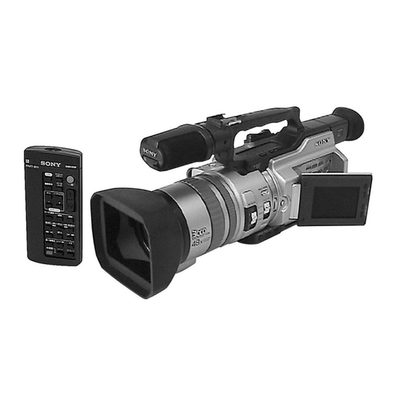
Photo : DCR-VX2000
For MECHANISM ADJUSTMENTS, refer to the
"DV MECHANICAL ADJUSTMENT MANUAL
C MECHANISM " (9-974-050-11).
DCR-VX2000
DCR-VX2000E : PAL model
SPECIFICATIONS
DIGITAL VIDEO CAMERA RECORDER
RMT-811
US Model
Canadian Model
Korea Model
DCR-VX2000
AEP Model
UK Model
Australian Model
Chinese Model
DCR-VX2000E
E Model
Hong Kong Model
Tourist Model
DCR-VX2000/VX2000E
C MECHANISM
: NTSC model
— Continued on next page —
Advertisement
Table of Contents

Related Manuals for Sony DCR-VX2000


Summary of Contents for Sony DCR-VX2000
- Page 1 Chinese Model DCR-VX2000E E Model Hong Kong Model Tourist Model DCR-VX2000/VX2000E Photo : DCR-VX2000 C MECHANISM For MECHANISM ADJUSTMENTS, refer to the On the VC-242 board “DV MECHANICAL ADJUSTMENT MANUAL This service manual provides the information that is premised the C MECHANISM ”...
-
Page 2: Supplied Accessories
MARK 0 ON THE SCHEMATIC DIAGRAMS AND IN THE PARTS CRITIQUES POUR LA SÉCURITÉ DE FONCTIONNEMENT. NE LIST ARE CRITICAL TO SAFE OPERATION. REPLACE THESE REMPLACER CES COMPOSANTS QUE PAR DES PIÈSES SONY COMPONENTS WITH SONY PARTS WHOSE PART NUMBERS DONT LES NUMÉROS SONT DONNÉS DANS CE MANUEL OU APPEAR AS SHOWN IN THIS MANUAL OR IN SUPPLEMENTS DANS LES SUPPÉMENTS PUBLIÉS PAR SONY. -
Page 3: Table Of Contents
TABLE OF CONTENTS SERVICE NOTE Erasing the cassette memory data ········································ 1-37 Customizing Your Camcorder ················································· 1-38 POWER SUPPLY DURING REPAIRS ····························· 6 Changing the menu settings ················································· 1-38 TO TAKE OUT A CASSETTE WHEN NOT EJECT Resetting the date and time ·················································· 1-40 (FORCE EJECT) ································································... -
Page 4: Schematic Diagrams
PRINTED WIRING BOARDS AND • MA-386 (AUDIO AMP) PRINTED WIRING BOARD ······················· 4-99 SCHEMATIC DIAGRAMS • MA-386 (AUDIO AMP) 4-1. FRAME SCHEMATIC DIAGRAM (1/3) ······················· 4-1 SCHEMATIC DIAGRAM ·························· 4-101 FRAME SCHEMATIC DIAGRAM (2/3) ······················· 4-3 • DD-138 (DC/DC CONVERTER, DC REGURATOR) FRAME SCHEMATIC DIAGRAM (3/3) ·······················... - Page 5 20-1. Steady Shot Adjustment (1) ··········································· 5-28 2-1. Preparations for recording ············································· 5-54 20-2. Steady Shot Adjustment (2) ··········································· 5-29 2-2. IC301 TRX (RF) REC BIST Check ····························· 5-54 1-4. COLOR ELECTRONIC VIEWFINDER SYSTEM 2-3. Processing after Completing Recording System Check ·· 5-54 ADJUSTMENT ·····························································...
-
Page 6: Service Note
SERVICE NOTE POWER SUPPLY DURING REPAIRS In this unit, about 10 seconds after power is supplied to the battery terminal using the regulated power supply (8.4V), the power is shut off so that the unit cannot operate. These following two methods are available to prevent this. Take note of which to use during repairs. Method 1. -
Page 7: Self-Diagnosis Function
SELF-DIAGNOSIS FUNCTION SELF-DIAGNOSIS DISPLAY SELF-DIAGNOSIS FUNCTION When problems occur while the unit is operating, the counter of the When problems occur while the unit is operating, the self-diagnosis viewfinder, LCD screen or LCD window consists of an alphabet function starts working, and displays on the viewfinder, LCD screen or LCD window what to do. -
Page 8: Self-Diagnosis Code Table
SELF-DIAGNOSIS CODE TABLE Self-diagnosis Code Block Detailed Symptom/State Correction Function Code Non-standard battery is used. Use the info LITHIUM battery. Condensation. Remove the cassette, and insert it again after one hour. Video head is dirty. Clean with the optional cleaning cassette. LOAD direction. -
Page 9: General
DCR-VX2000/VX2000E SECTION 1 This section is extracted from instruction GENERAL manual. (DCR-VX2000E model) - Page 18 1-10...
- Page 19 1-11...
- Page 20 1-12...
- Page 21 1-13...
- Page 22 1-14...
- Page 23 1-15...
- Page 24 1-16...
- Page 25 1-17...
- Page 26 1-18...
- Page 27 1-19...
- Page 28 1-20...
- Page 29 1-21...
- Page 30 1-22...
- Page 31 1-23...
- Page 32 1-24...
- Page 33 1-25...
- Page 34 1-26...
- Page 35 1-27...
- Page 36 1-28...
- Page 37 1-29...
- Page 38 1-30...
- Page 39 1-31...
- Page 40 1-32...
- Page 41 1-33...
- Page 42 1-34...
- Page 43 1-35...
- Page 44 1-36...
- Page 45 1-37...
- Page 46 1-38...
- Page 47 1-39...
- Page 48 1-40...
- Page 49 1-41...
- Page 50 1-42...
- Page 51 1-43...
- Page 52 1-44...
- Page 53 1-45...
- Page 54 1-46...
- Page 55 1-47...
- Page 56 1-48...
- Page 57 1-49...
- Page 58 1-50...
- Page 59 1-51...
- Page 60 1-52...
- Page 61 1-53...
- Page 62 1-54...
- Page 63 1-55...
- Page 64 1-56...
- Page 65 1-57...
- Page 66 1-58...
- Page 67 1-59E...
- Page 68 DCR-VX2000/VX2000E SECTION 2 DISASSEMBLY The following flow chart shows the disassembly procedure. 2-1. LCD section HL-011, PD-126 boards service position (HL-011, PD-126 boards, Inverter transformer unit) LB-065 board service position 2-2. EVF section (LB-065 board) 2-4. FK-076, MA-386, MI-038, FT-090 boards 2-3.
-
Page 69: Lcd Section (Hl-011, Pd-126 Boards, Inverter Transformer Unit)
NOTE: Follow the disassembly procedure in the numerical order given. 2-1. LCD SECTION (HL-011, PD-126 BOARDS, INVERTER TRANSFORMER UNIT) REMOVING THE PD-126 BOARD, INVERTER TRANSFORMER UNIT 2 Two screws (M2 × 3), 3 P cabinet (C) assembly 4 Harness spring bolt (CP-093) (8P) 6 LCD frame, BL retainer,... -
Page 70: Evf Section (Lb-065 Board)
2-2. EVF SECTION (LB-065 BOARD) 4 EVF front cabinet (upper) 2 EVF rear cabinet assembly 1 Push the lock knob in the direction of the arrow A and remove the EVF rear cabinet assembly in the direction of the arrow B . 3 Two tapping screws (M1.7 ×... -
Page 71: Boards
2-4. FK-076, MA-386, MI-038, FT-090 BOARDS 5 Two screws 9 FP-201 flexible board (15P) 6 Handle cover (M2 × 5), q; Two screws (M2 × 3), assembly spring bolt spring bolt qa Outer connector (hot shoe), Strap sheet metal (F), qg Screw (M2 ×... -
Page 72: Cabinet (L) Block Assembly, Mechanism
2-5. CABINET (L) BLOCK ASSEMBLY, MECHANISM DECK, VC-242, DD-138, JK-190 BOARDS (FOR FORCE EJECT OF CASSETTE AND VTR SECTION CHECK) 3 Screw (M2 × 5), spring bolt 6 Cabinet (L) block assembly 1 Screw (FOR FORCE EJECT OF CASSETTE) (M2 × 5), spring bolt 2 Screw 4 Screw... - Page 73 [MECHANISM DECK SERVICE POSITION-1] Note: Use the parts only which can be removed easily from outside of the mechanism deck. Adjustment remote commander (RM-95) CPC-13 jig Mechanism deck (J-6082-443-A) AC POWER AC IN ADAPTOR Cabinet (L) block assembly [SERVICE POSITION TO CHECK THE VTR SECTION] Connection to Check the VTR Section To check the VTR Section, set the VTR to the "forced VTR power ON"...
-
Page 74: Cabinet (R) Block Assembly
2-6. CABINET (R) BLOCK ASSEMBLY 5 Screw (M2 × 5), spring bolt 7 Cabinet (R) block assembly 6 Two screws (M2 × 5), spring bolt 1 Screw (M2 × 5), spring bolt 3 CF ornamental plate 4 Two screws (M2 × 5), spring bolt 2 Claw CPC-13 jig... -
Page 75: Battery Panel Block Assembly (Mk-014, Kp-010, Ms-049 Boards)
2-8. BATTERY PANEL BLOCK ASSEMBLY (MK-014, KP-010, MS-049 BOARDS) 8 Screw (M2 × 5), 9 CPC cover spring bolt q; Battery panel block assembly 7 Two screws (M2 × 5), spring bolt 6 Two screws (M2 × 5), spring bolt 4 Screw (M2 ×... - Page 76 2-10.LA-026, DD-138, VC-242, JK-190 BOARDS, MECHANISM DECK 1 Screw (M2 × 3), spring bolt 2 Flexible retainer 8 Screw (M2 × 3), spring bolt 9 LA joint 3 FP-188 flexible board (6P) 7 LA-026 board 6 Three screws (M2 × 3), spring bolt 5 Flexible board (27P) (from VAP assembly)
-
Page 77: Mechanism Deck
2-11.LENS BLOCK ASSEMBLY, CENTER FRAME ASSEMBLY qs FP-188 flexible board (6P) qd Center frame assembly q; Two screws (M2 × 4), 6 Screw lock ace (M2 × 3), qa Two screws (M2 × 3), spring bolt spring bolt 9 Lens block assembly PRECAUTION DURING INSTALLATION When installing it. -
Page 78: Assembly
2-12.CD-254, SE-108 BOARDS, ZOOM LENS ASSEMBLY 1 Three tapping 4 Three tapping screws screws (M1.7 × 7) (B2 × 5) 5 SE-108 board 2 (CCD) flexible block assembly 3 Flexible board (6P) (from zoom lens assembly) REMOVING THE CD-254 BOARD 9 Zoom lens 8 Remove the soldering. - Page 79 [CONNECTION DIAGRAM FOR SERVICE POSITION (Mainly for voltage measurement and check)] CK-093, VC-242, JK-190, CD-254, DD-138, LA-026, KP-010, MK-014, MS-049 BOARDS, MECHANISM DECK-2 Battery panel assembly AC POWER AC IN ADAPTOR CPC-13 jig DC-IN (J-6082-443-A) connector (3P) (1-794-637-11) Battery terminal board (4P) KP-010 board MK-014 board DD-138 board...
- Page 80 2-15.CONTROL SWITCH BLOCK (ED-4980), HINGE ASSEMBLY Start the removal work after the LCD section has been removed referring section 2-1. 2 Control switch block (ED-4980) 1 Bright button 3 Blind door (D) assembly 2 Screw (M1.7 × 2.5), 2 Hinge lid 3 Three claws lock ace q;...
- Page 81 2-16.CIRCUIT BOARDS LOCATION The circuit boards contained in the zoom lens are not shown. LB-065 MA-386 MI-038 (BACK LIGHT) (AUDIO AMP) CK-093 (MIC IN) (KEY IN) FT-090 (REMOTE) PD-126 (RGB DRIVE/TG) INVERTER TRANSFORMER UNIT HL-011 (LCD DRIVE) SE-108 CD-254 (VAP SENSOR) (CCD IMAGER) FK-076 (CONTROL SWITCH)
-
Page 82: Control Switch Block (Ps-4980)
2-17.FLEXIBLE BOARDS LOCATION The flexible boards contained in the mechanism deck and that in the zoom lens are not shown. FP-193 FP-202 FP-201 FP-200 FP-198 FP-199 FP-194 FP-190 FP-196 FP-189 FP-188 FP-195 CONTROL SWITCH BLOCK FP-191 (ED-4980) CONTROL SWITCH BLOCK FP-186 (PS-4980) FP-197... -
Page 83: Block Diagrams
DCR-VX2000/VX2000E SECTION 3 BLOCK DIAGRAMS 3-1. OVERALL BLOCK DIAGRAM (1/4) ( ) : Page No. shown in ( ) indicates the page to refer on the schematic diagram. CD-254 BOARD VC-242 BOARD(1/4) (4-9) (4-9) IC103 AGC CONT 1,2 R,B GAIN... -
Page 84: Overall Block Diagram (2/4)
DCR-VX2000/VX2000E 3-2. OVERALL BLOCK DIAGRAM (2/4) ( ) : Page No. shown in ( ) indicates the page to refer on the schematic diagram. CN300 VC-242 BOARD(2/4) IN/OUT (4-23) (4-17) X301 24.576MHz IC301 IC1407 CN006 CN301 (4-26) SPCK SPCK TPA+,-... -
Page 85: Overall Block Diagram (3/4)
DCR-VX2000/VX2000E 3-3. OVERALL BLOCK DIAGRAM (3/4) ( ) : Page No. shown in ( ) indicates the page to refer on the schematic diagram. CN007 C MECHA DECK FOR ADJUSTMENTS (SEE PAGE 4-39) (4-28) VC-242 BOARD(3/4) RF MON IC102 REC CK... -
Page 86: Overall Block Diagram (4/4)
DCR-VX2000/VX2000E 3-4. OVERALL BLOCK DIAGRAM (4/4) ( ) : Page No. shown in ( ) indicates the page to refer on the schematic diagram. FP-196 HL-011 BOARD CK-093 VC-242 BOARD(4/4) (4-44) CN1702 (FLEXIBLE) BOARD(2/2) ED-4980 CK-093 BOARD(1/2) IC1104 VOLUME SW... -
Page 87: Power Block Diagram (1/3)
DCR-VX2000/VX2000E 3-5. POWER BLOCK DIAGRAM (1/3) ( ) : Page No. shown in ( ) indicates the page to refer on the schematic diagram. CHARGE INH DD-138 BOARD SHOE ON (4-61) SHOE UNREG BATT SIG Q329, INIT CHARGE ON J901... - Page 88 DCR-VX2000/VX2000E 3-6. POWER BLOCK DIAGRAM (2/3) ( ) : Page No. shown in ( ) indicates the page to refer on the schematic diagram. VC-242 BOARD IC1104 (4-44) JK-190 BOARD CN021 HI CONTROL CHARGE INH J303 SHOE ON LANC DC...
- Page 89 DCR-VX2000/VX2000E 3-7. POWER BLOCK DIAGRAM (3/3) ( ) : Page No. shown in ( ) indicates the page to refer on the schematic diagram. PD-126 BOARD PANEL 4.6V PANEL 2.8V Q2102,2104 PANEL 13.5V L2103 CN2100 CN2104 UNIT L2101 L2102 P OFF...
-
Page 90: Printed Wiring Boards And Schematic Diagrams
DCR-VX2000/VX2000E SECTION 4 PRINTED WIRING BOARDS AND SCHEMATIC DIAGRAMS 4-1. FRAME SCHEMATIC DIAGRAM (1/3) CN025 CN100 IMAGER SUBB CD-254 BOARD VDDB B_CCD_OUT IMAGER LENS UNIT V2BB VDD2B V2AB IMAGER SE-108 R_CCD_OUT BOARD VDD2R V2AR V2BR CONTINUED ON (SEE PAGE 4-3) -
Page 91: Frame Schematic Diagram (1/3)
DCR-VX2000/VX2000E FRAME SCHEMATIC DIAGRAM (2/3) CN100 CN025 JK-190 BOARD LB-065 BOARD SUBB LCD903 UNIT VDDB J300 B_CCD_OUT VIDEO V2BB ND200 VDD2B BACK V2AB AUDIO LIGHT J301 CN300 J302 J303 R_CCD_OUT S-VIDEO DV IN/OUT LANC VDD2R CONTINUED ON V2BR V2AR (SEE PAGE... -
Page 92: Frame Schematic Diagram (2/3)
DCR-VX2000/VX2000E FRAME SCHEMATIC DIAGRAM (3/3) FP-197 CONTROL SWITCH FP-194 BLOCK(ED-4980) FLEXIBLE FLEXIBLE S001 ND201 BACK-LIGHT (RVS) S001 CONTROL S002 DIAL COLOR MENU (OPEN/CLOSE) LCD901 UNIT INVERTER UNIT CN253 SP901 SPEAKER CN251 CN2100 CK-093 BOARD PANEL_B PANEL_B CN250 PANEL_G PANEL_G P_UNREG_GND... -
Page 93: Printed Wiring Board
DCR-VX2000/VX2000E DCR-VX2000/VX2000E 4-2. PRINTED WIRING BOARDS AND SCHEMATIC DIAGRAMS THIS NOTE IS COMMON FOR WIRING BOARDS AND SCHEMATIC DIAGRAMS (In addition to this, the necessary note is printed in each block) (For printed wiring boards) (Measuring conditions voltage and waveform) •... - Page 94 R103 C105 4700 4.7u L105 100uH C108 R111 6.3V R110 C110 NTSC MODEL:DCR-VX2000 R105 4.7u PAL MODEL :DCR-VX2000E 5600 IC105 BUFFER Precautions Upon Replacing CCD Imager IC100 IC105 AD8014ART-REEL7 • The CD-254 board mounted as a repair part is not equipped B-CH CCD with a CCD imager.
-
Page 95: Printed Wiring Board
DCR-VX2000/VX2000E CD-254 (CCD IMAGER) PRINTED WIRING BOARD — Ref. No. CD-254 Board; 1,000 Series — For printed wiring board • Refer to page 4-116 for parts location. • This board is four-layer print board. However, the pat- terns of layers two and three have not been included in the diagram. - Page 96 Schematic diagram and printed wiring board of the VC-242 board are not shown. Pages from 4-13 to 4-54 are not shown.
- Page 97 DCR-VX2000/VX2000E JK-190 (JACK BOARD) PRINTED WIRING BOARD — Ref. No. JK-190 Board; 2,000 Series — AUDIO DV IN/OUT For printed wiring board VC-242 • Refer to page 4-116 for parts location. S/H AGC, TG, CAMERA SIGNAL PROCESS, MS I/F, RS232C I/F, STILL CONTROL, MS DRIVE, •...
- Page 98 DCR-VX2000/VX2000E SIGNAL PATH JK-190 BOARD VIDEO SIGNAL JACK BOARD AUDIO -REF.NO.:2000 SERIES- CHROMA Y/CHROMA SIGNAL XX MARK:NO MOUNT J301 FB300 FB301 CN301 S VIDEO LANC_GND/232C_TD LANC_GND/232C_TD R311 HP_JACK_IN XSJACK_IN LANC_SIG/232C_RD LANC_SIG/232C_RD S_C_I/O R312 HP_R_OUT XLANC_JACK_IN S_Y_I/O R313 HP_L_OUT XLANC_JACK_IN LANC_DC...
- Page 99 DCR-VX2000/VX2000E CK-093 (KEY IN) PRINTED WIRING BOARD — Ref. No. CK-093 Board; 1,000 Series — For printed wiring board LB-065 MA-386 • Refer to page 4-116 for parts location. MI-038 (AUDIO AMP) (BACK LIGHT) CK-093 (MIC IN) • This board is six-layer print board. However, the pat-...
-
Page 100: Key In
DCR-VX2000/VX2000E CK-093 BOARD CONTROL SWITCH BLOCK(ED-4980) KEY IN S001 -REF.NO.:1000 SERIES- EXPOSURE BUTTON XX MARK:NO MOUNT CN255 S002 DIAL_C(EXP/IRIS) DIAL_C EXPOSURE DIAL DIAL_D(EXP/IRIS) DIAL_D CN251 2.8V(DIAL) D_2.8V PANEL_B EXPOSURE/IRIS EXPOSURE/IRIS PANEL_G REG_GND REG_GND PANEL_R REG_GND REG_GND REG_GND S263 R250 S255... -
Page 101: Printed Wiring Board
DCR-VX2000/VX2000E PD-126 (RGB DRIVE, TG) PRINTED WIRING BOARD — Ref. No. PD-126 Board; 20,000 Series — FP-194 FLEXIBLE BOARD S001 S001 MENU 1-678-061- FP-200 FP-198 FP-194 FP-188 CONTROL SWITCH BLOCK (ED-4980) For printed wiring board LB-065 MA-386 • Refer to page 4-116 for parts location. - Page 102 DCR-VX2000/VX2000E For Schematic Diagram • Refer to page 4-109 for waveforms. PD-126 BOARD Note : Resistor is mounted to the L2105 Location where C2129 is printed. RGB DRIVE/TG L2103 10uH R2161 2520 -REF.NO.:20000 SERIES- C2115 XX MARK:NO MOUNT 3.3u R2165...
-
Page 103: Printed Wiring Board
DCR-VX2000/VX2000E LA-026 (ZOOM/FOCUS DRIVE, VAP DRIVE, KEY IN/CONNECTOR) PRINTED WIRING BOARD — Ref. No. LA-026 Board; 20,000 Series — For printed wiring board VC-242 • Refer to page 4-117 for parts location. S/H AGC, TG, CAMERA SIGNAL PROCESS, MS I/F, RS232C I/F, STILL CONTROL, MS DRIVE, •... -
Page 104: Printed Wiring Board
DCR-VX2000/VX2000E For Schematic Diagram • Refer to page 4-75 for SE-108 printed wiring board. LA-026 BOARD(1/3) ZOOM/FOCUS DRIVE(LA BLOCK) -REF.NO.:20000 SERIES- XX MARK:NO MOUNT NO MARK:REC/PB MODE HALL_AD TO(3/3) SE-108 BOARD R :REC MODE P :PB MODE SE603 VAP SENSOR -REF.NO.:1000 SERIES-... -
Page 105: Vap Drive
DCR-VX2000/VX2000E For Schematic Diagram • Refer to page 4-67 for printed wiring board. LA-026 BOARD(2/3) Q071 Q070 R5.1/P0 2SB1462J-QR(K8).SO 2SB1462J-QR(K8).SO VAP DRIVE(LD BLOCK) R085 IC072 IC072 Q070,071 -REF.NO.:20000 SERIES- 1/8W LB1830M-TLM PROTECT C076 VAP DRIVE Q076 XX MARK:NO MOUNT 2SA1588-OY-TE85L R5.1/P0... -
Page 106: Key In/Connector
DCR-VX2000/VX2000E For Schematic Diagram • Refer to page 4-67 for printed wiring board. LA-026 BOARD(3/3) KEY IN/CONNECTOR NO MARK:REC/PB MODE R :REC MODE -REF.NO.:20000 SERIES- P :PB MODE XX MARK:NO MOUNT FP-189 FLEXIBLE CN054 FADER FADER BACK_LIGHT BACK_LIGHT SPOT_LIGHT SPOT_LIGHT LND051 N.C. -
Page 107: Vap Sensor
DCR-VX2000/VX2000E SE-108 (VAP SENSOR) PRINTED WIRING BOARD — Ref. No. SE-108 Board; 1,000 Series — For printed wiring board FP-188 FLEXIBLE BOARD FP-189 FLEXIBLE BOARD • Refer to page 4-117 for parts location. • This board is six-layer print board. However, the pat-... -
Page 108: Ms Connector
DCR-VX2000/VX2000E MS-049 (MS CONNECTOR) PRINTED WIRING BOARD — Ref. No. MS-049 Board; 20,000 Series — For printed wiring board VC-242 • Refer to page 4-117 for parts location. S/H AGC, TG, CAMERA SIGNAL PROCESS, MS I/F, RS232C I/F, STILL CONTROL, MS DRIVE, •... - Page 109 DCR-VX2000/VX2000E KP-010 (SELECT DIAL), MK-014 (CONTROL KEY) PRINTED WIRING BOARDS — Ref. No. KP-010, MK-014 Boards; 10,000 Series — For printed wiring boards • Refer to page 4-117 for parts location. • These boards are six-layer print board. However, the patterns of layers two to five have not been included in the diagrams.
-
Page 110: Select Dial
DCR-VX2000/VX2000E DCR-VX2000/VX2000E For Schematic Diagram • Refer to page 4-77 for MS-049 printed wiring board. KP-010 BOARD SELECT DIAL -REF.NO.:1000 SERIES- XX MARK:NO MOUNT CN550 DIAL_A LA-026 EXECUTE BOARD(3/3) CN056 (SEE PAGE 4-74) DIAL_B S550 SEL/PUSH EXEC D550 LND550 01BZA8.2(TE85L) CH.GND... -
Page 111: Printed Wiring Board
DCR-VX2000/VX2000E FK-076 (CONTROL SWITCH) PRINTED WIRING BOARD — Ref. No. FK-076 Board; 1,000 Series — For printed wiring board • Refer to page 4-117 for parts location. • This board is six-layer print board. However, the pat- terns of layers two to five have not been included in the diagram. - Page 112 DCR-VX2000/VX2000E FK-076 BOARD CONTROL SWITCH BLOCK(CF-4980) R502 R505 R508 R511 R514 R516 CONTROL SWITCH CN011 -REF.NO.:1000 SERIES- RV800 XX MARK:NO MOUNT D_2.8V S811 ZOOM_VR_AD PHOTO FREEZE XPHOTO_FREEZE XPHOTO_REC XEJECT_SW VC-242 BOARD(15/18) R500 CN009 XS/S_SW PHOTO REC PHOTO_STBY_SW R503 R506 R509...
-
Page 113: Printed Wiring Board
DCR-VX2000/VX2000E MI-038 (MIC IN), FT-090 (REMOTE) PRINTED WIRING BOARD — Ref. No. MI-038, FT-090 Boards; 1,000 Series — FP-198 FLEXIBLE BOARD J001 LINE For printed wiring boards LB-065 MA-386 • Refer to page 4-118 for parts location. MI-038 (BACK LIGHT) -
Page 114: Mic In
DCR-VX2000/VX2000E FT-090 BOARD NO MARK:REC/PB MODE MI-038 BOARD NO MARK:REC/PB MODE R :REC MODE R :REC MODE P :PB MODE REMOTE MIC IN P :PB MODE FP-199 -REF.NO.:1000 SERIES- -REF.NO.:1000 SERIES- CN702 FLEXIBLE CN750 XX MARK:NO MOUNT XX MARK:NO MOUNT... - Page 115 DCR-VX2000/VX2000E DCR-VX2000/VX2000E LB-065 (BACK LIGHT) PRINTED WIRING BOARD — Ref. No. LB-065 Board; 1,000 Series — For printed wiring board LB-065 MA-386 • Refer to page 4-118 for parts location. MI-038 (AUDIO AMP) (BACK LIGHT) CK-093 (MIC IN) • This board is four-layer print board. However, the pat-...
- Page 116 DCR-VX2000/VX2000E For Schematic Diagram • Refer to page 4-109 for waveform. LB-065 BOARD NO MARK:REC/PB MODE R :REC MODE R206 R207 BACK LIGHT 100k P :PB MODE 100k FP-193 -REF.NO.:1000 SERIES- R205 R208 FLEXIBLE XX MARK:NO MOUNT 100k 100k CN200...
- Page 117 DCR-VX2000/VX2000E HL-011 (LCD DRIVE) PRINTED WIRING BOARD — Ref. No. HL-011 Board; 20,000 Series — FP-196 FLEXIBLE BOARD S001 S001 LCD BRIGHT+ S002 LCD BRIGHT– S002 1-678-063- S003 S003 VOLUME+ S004 VOLUME– S004 For printed wiring board LB-065 MA-386 FP-193 •...
- Page 118 DCR-VX2000/VX2000E For Schematic Diagram • Refer to page 4-110 for waveform. HL-011 BOARD NO MARK:REC/PB MODE R :REC MODE LCD DRIVE P :PB MODE -REF.NO.:20000 SERIES- XX MARK:NO MOUNT FP-195 FLEXIBLE CN1701 COM1 REG_GND REG_GND REG_GND COM1 XCS_LCD_DRIVER XCS_LCD_DRIVER XCS_LCD_DRIVER...
- Page 119 DCR-VX2000/VX2000E MA-386 (AUDIO AMP) PRINTED WIRING BOARD — Ref. No. MA-386 Board; 20,000 Series — For printed wiring board LB-065 MA-386 • Refer to page 4-118 for parts location. MI-038 (AUDIO AMP) (BACK LIGHT) CK-093 (MIC IN) • This board is four-layer print board. However, the pat-...
- Page 120 DCR-VX2000/VX2000E MA-386 BOARD NO MARK:REC/PB MODE R :REC MODE P :PB MODE AUDIO AMP SIGNAL PATH -REF.NO.:20000 SERIES- XX MARK:NO MOUNT AUDIO SIGNAL CN1100 SIRCS_SIG1 SIRCS_SIG1 SIRCS_PWM SIRCS_PWM MT_5.2V F_TALLY_LED FP-201 FLEXIBLE CN1102 F_TALLY_LED D_3.1V SHOE_UNREG SHOE_UNREG MT_GND SHOE_UNREG SHOE_UNREG...
-
Page 121: Dc/Dc Converter, Dc Regurator
DCR-VX2000/VX2000E DD-138 (DC/DC CONVERTER, DC REGURATOR) PRINTED WIRING BOARD — Ref. No. DD-138 Board; 1,000 Series — For printed wiring board VC-242 • Refer to page 4-119 for parts location. S/H AGC, TG, CAMERA SIGNAL PROCESS, MS I/F, RS232C I/F, STILL CONTROL, MS DRIVE, •... -
Page 122: Dc/Dc Converter
DCR-VX2000/VX2000E For Schematic Diagram • Refer to page 4-110 for waveforms. DD-138 BOARD(1/2) DC/DC CONVERTER(DD-1 BLOCK) -REF.NO.:1000 SERIES- CHARGE_INH TO(2/2) R300 XX MARK:NO MOUNT BATT/XEXT_SW TO(2/2) BATT_SIG NO MARK:REC/PB MODE FAST_CHARGE TO(2/2) R :REC MODE P :PB MODE INIT_CHARGE_ON TO(2/2) -
Page 123: Dc Regurator
DCR-VX2000/VX2000E For Schematic Diagram • Refer to page 4-103 for printed wiring board. SIGNAL PATH DD-138 BOARD(2/2) REC/PB DC REGURATOR(DD-2 BLOCK) -REF.NO.:1000 SERIES- Drum speed servo XX MARK:NO MOUNT Drum phase servo NO MARK:REC/PB MODE Drum servo (speed and phase) -
Page 124: Waveforms
DCR-VX2000/VX2000E 4-3. WAVEFORMS CD-254 PD-126 LB-065 BOARD BOARD BOARD REC/PB REC/PB IC100, 101, 102 1,2 IC2101 rh IC2103 rk IC200 4 2.9Vp-p 8Vp-p 500mVp-p 4.6Vp-p IC2101 rj IC100, 101, 102 3,4 19.5Vp-p 440mVp-p 17msec IC2101 rk IC100, 101, 102 qa... - Page 125 DCR-VX2000/VX2000E HL-011 DD-138 BOARD BOARD (1/2) REC/PB CAMERA REC IC1701 2 IC300 rj 3.0Vp-p 5.2Vp-p 38 µsec 2.5 µsec IC300 t; 5.2Vp-p 2.5 µsec IC300 td 5.2Vp-p 2.5 µsec IC300 th 5.2Vp-p 2.5 µsec IC300 tk 5.2Vp-p 2.5 µsec IC300 ya 5.2Vp-p...
- Page 126 Waveforms and parts location of the VC-242 board are not shown. Pages from 4-111 to 4-115 are not shown.
-
Page 127: Mounted Parts Location
DCR-VX2000/VX2000E 4-4. MOUNTED PARTS LOCATION CD-254 BOARD (SIDE A) JK-190 BOARD (SIDE A) CK-093 BOARD (SIDE A) PD-126 BOARD (SIDE A) C100 L100 CN300 A-4 J300 BT250 D253 C2101 Q2108 B-1 C101 L101 J301 D254 C2102 Q2109 B-3 C102 L104... - Page 128 DCR-VX2000/VX2000E LA-026 BOARD (SIDE A) LA-026 BOARD (SIDE B) SE-108 BOARD (SIDE A) MK-014 BOARD (SIDE A) C095 R067 C070 R056 SE600 CN001 B-1 C140 R112 C071 R057 SE601 C141 R114 C072 R058 SE602 D004 C142 R118 C073 R061 SE603...
- Page 129 DCR-VX2000/VX2000E MI-038 BOARD (SIDE A) LB-065 BOARD (SIDE A) MA-386 BOARD (SIDE A) C700 Q704 C201 C1109 D-10 R1121 D-9 C702 Q705 C202 R1122 D-10 C704 Q706 C203 CN100 D-1 R1123 D-10 C709 CN1102 D-2 R1124 D-10 C711 R701 CN201 A-1...
- Page 130 DCR-VX2000/VX2000E DD-138 BOARD (SIDE A) DD-138 BOARD (SIDE B) C300 L312 C301 L310 R337 C306 L314 C302 L311 R338 C308 L315 C303 L313 R339 C310 L317 C304 L316 R340 C313 L318 C305 R341 C314 L319 C307 Q309 R342 C316 L451...
-
Page 131: Adjustments
DCR-VX2000/VX2000E SECTION 5 ADJUSTMENTS Before starting adjustment EVR Data Re-writing Procedure When Replacing Board The data that is stored in the repair board, is not necessarily correct. Perform either procedure 1 or procedure 2 or procedure 3 when replacing board. -
Page 132: Adjusting Items When Replacing Main Parts And Boards
1-1. Adjusting items when replacing main parts and boards. • Adjusting items when replacing main parts When replacing main parts, adjust the items indicated by z in the following table. Note1: When replacing the drum assy., reset the data of page: 2, address: A2 to A4 to “00”. (Refer to “Record of Use check” of “5-4. SERVICE MODE”) Replaced parts Block replacement Parts replacement... - Page 133 • Adjusting items when replacing a board or EEPROM When replacing a board or EEPROM, adjust the items indicated by z in the following table. Board replacement Adjustment Adjustment Section Initialization of C, D, 8 page data Initialization Initialization of B page data of B, C, D, E, Initialization of E, F page data F, 8 page data...
-
Page 134: Camera Section Adjustment
5-1. CAMERA SECTION ADJUSTMENT 1-1. PREPARATIONS BEFORE ADJUSTMENT (CAMERA SECTION) 1-1-1. List of Service Tools • Oscilloscope • Color monitor • Vectorscope • Regulated power supply • Digital voltmeter Ref. No. Name Parts Code Usage Auto white balance adjustment/check Filter for color temperature correction (C14) J-6080-058-A White balance adjustment/check ND filter 1.0... -
Page 135: Preparations
1-1-2. Preparations Note 1: For details of how remove the cabinet and boards, refer to “2. DISASSEMBLY”. Pattern box Note 2: When performing only the adjustments, the lens block and boards need not be disassembled. Connect the equipment for adjustments according to Fig. 5-1-3. Note 3: As removing the cabinet (R) (removing the VC-242 board CN008) means removing the lithium 3V power supply (CK-093 board 95 cm... - Page 136 Must be connected when performing the audio system adjustments. Cabinet (L) Handle, cabinet (Top) FK-076 board CN501 FP-200 flexible Must be connected when Adjustment remote commander using the VTR function keys. Control switch block (CF-4980) CPC-13 jig (J-6082-443-A) Must be connected when using the POWER switch or EJECT switch.
-
Page 137: Precaution
1-1-3. Precaution 1. Setting the Switch Unless otherwise specified, set the switches as follows and perform adjustments without loading cassette. POWER switch (CF-4980 block) ......CAMERA 10. BACK LIGHT (FP-189 flexible) ........OFF DEMO MODE (Menu display) ........OFF 11. SPOT LIGHT (FP-189 flexible) ........OFF DIGITAL ZOOM (Menu display) ........ -
Page 138: Initialization Of B, C, D, E, F, 8 Page Data
1-2. INITIALIZATION OF B, C, D, E, F, 8 PAGE DATA 1-2-1. INITIALIZATION OF C, D, 8 PAGE DATA 1. Initializing the C, D, 8 Page Data 2. Modification of C, D, 8 Page Data If the C, D, 8 page data has been initialized, change the data of the Note1: If “Initializing the C, D, 8 Page Data”... - Page 139 Address Remark Address Remark Initial value Initial value 23 to 24 Fixed data-1 Fixed data-2 S VIDEO out Y level adj. S VIDEO out Cr level adj. CA to E7 Fixed data-1 S VIDEO out Cb level adj. Serial No. input Chroma BPF f adj.
- Page 140 4. D Page Table Address Remark Initial value Note: Fixed data-1: Initialized data. (Refer to “1. Initializing the C, D, 8 4D to 4E Fixed data-1 Page Data”.) Fixed data-2 Fixed data-2: Modified data. (Refer to “2. Modification of C, D, 8 Page Data”.) Address Remark...
-
Page 141: Page Table
5. 8 Page Table Address Remark Initial value Note: Fixed data-1: Initialized data. (Refer to “1. Initializing the C, D, 8 B1 to B8 Fixed data-1 Page Data”.) Fixed data-2 Fixed data-2: Modified data. (Refer to “2. Modification of C, D, 8 Page Data”.) BB to C3 Fixed data-1... - Page 142 1-2-2. INITIALIZATION OF B PAGE DATA Note: When reading the B page data, insert a “Memory Stick” into the “Memory Stick” slot. Switch setting: POWER ..............MEMORY 2. Modification of B Page Data 1. Initializing the B Page Data Note: If the B page data has been initialized, the following adjustments If the B page data has been initialized, change the data of the “Fixed need to be performed again.
-
Page 143: Modification Of B Page Data
Order Page Address Data Procedure Set the following data, and press Set the data. PAUSE button. 2D: DCR-VX2000 (NTSC) Set the data, and press PAUSE 2F : DCR-VX2000E (PAL) button. Set the data, and press PAUSE Set the data, and press PAUSE button. - Page 144 4. F Page Table Initial value Address Remark Note1: Fixed data-1: Initialized data. (Refer to “1. Initializing the E, F NTSC PAL Page Data”.) Fixed data-2 Fixed data-2: Modified data. (Refer to “2. Modification of E, F Page Data”.) 61 to 6A Fixed data-1 Fixed data-2 Initial value...
- Page 145 5. E Page Table Initial value Address Remark Note1: Fixed data-1: Initialized data. (Refer to “1. Initializing the E, F NTSC PAL Page Data”.) 95 to A0 Fixed data-1 Fixed data-2: Modified data. (Refer to “2. Modification of E, F Page Data”.) Fixed data-2 Note2: Refer to “2.
-
Page 146: Camera System Adjustments
1-3. CAMERA SYSTEM ADJUSTMENTS Before perform the camera system adjustments, check that the specified values of “VIDEO SYSTEM ADJUSTMENT” are satisfied. 1. 27MHz Origin Oscillation Adjustment 2. Zoom Key Center Adjustment (VC-242 board) Set the A/D value center of the microprocessor to the center voltage Set the frequency of the clock for synchronization. -
Page 147: Hall Adjustment
3. HALL Adjustment 4. Offset Adjustment For detecting the position of the lens iris, adjust AMP gain and Adjust so that the AGC OUT potential lies within the specified value offset. of the digital clamp. Subject Not required Subject Not required Measurement Point Display data of page 1 (Note1) Measurement Point... -
Page 148: Flange Back Adjustment (Using Minipattern Box)
5. Flange Back Adjustment (Using Minipattern Box) The inner focus lens flange back adjustment is carried out automatically. In whichever case, the focus will be deviated during auto focusing/manual focusing. Subject Siemens star chart with ND filter for the minipattern box (Note2) Measurement Point Check operation on TV monitor Measuring Instrument... -
Page 149: Flange Back Adjustment
6. Flange Back Adjustment (Using Flange Back Adjustment Chart and Subject More Than 500m Away) The inner focus lens flange back adjustment is carried out automatically. In whichever case, the focus will be deviated during auto focusing/manual focusing. 6-1. Flange Back Adjustment (1) 6-2. -
Page 150: Flange Back Check
7. Flange Back Check Subject Siemens star (2.0m from the front of the protection glass) (Luminance : approx. 300 ± 50 lux) Measurement Point Check operation on TV monitor Measuring Instrument Specified Value Focused at the TELE end and WIDE end. -
Page 151: Pre White Balance Data Input
9. Pre White Balance Data Input 10. Auto White Balance Standard Data Input At 3200k, input the pre white balance standard data. At 3200K, input the white balance standard data. Subject Clear chart Subject Clear chart (Color bar standard picture frame) (Color bar standard picture frame) Adjustment Page Adjustment Page... -
Page 152: Max Gain Adjustment
11. MAX GAIN Adjustment 12. LV Standard Data Input Setting the minimum illumination. Adjust the normal coefficient of the light value. If it is not consistent, the image level required for taking subjects in Subject Clear chart low illuminance will not be produced (dark). (Color bar standard picture frame) Subject Clear chart... -
Page 153: White Balance Nd Filter 1 Compensation
13. White Balance ND Filter 1 Compensation 14. White Balance ND Filter 2 Compensation Compensate the white balance deviation when ND FILTER switch Compensate the white balance deviation when ND FILTER switch is “1”. is “2”. Subject Clear chart Subject Clear chart (Color bar standard picture frame) (Color bar standard picture frame) -
Page 154: Auto White Balance Adjustment
15. Auto White Balance Adjustment 16. Color Reproduction Adjustment (ND Filter OFF) Adjust to the proper auto white balance output data. When the ND FILTER switch is “OFF”, adjust the color difference If it is not correct, auto white balance and color reproducibility will matrix coefficient so that proper color reproduction is produced. -
Page 155: Color Reproduction Adjustment (Nd Filter 1)
17. Color Reproduction Adjustment (ND Filter 1) 18. Color Reproduction Adjustment (ND Filter 2) When the ND FILTER switch is “1”, adjust the color difference When the ND FILTER switch is “2”, adjust the color difference matrix coefficient so that proper color reproduction is produced. matrix coefficient so that proper color reproduction is produced. -
Page 156: White Balance Check
19. White Balance Check Processing after Completing Adjustments Subject Clear chart Order Page Address Data Procedure (Color bar standard picture frame) Filter Filter C14 for color temperature Set the data, and press PAUSE correction button. ND filter 1.0 and 0.3 (2 sheets) Set the data. -
Page 157: Steady Shot Adjustment
20. Steady Shot Adjustment • This adjustment is performed only when replacing the angular velocity sensor. Although this adjustment need not be performed when the circuit is damaged, etc., check the operations. • Note down the sensitivity displayed on the angular velocity sensor of the repair parts. -
Page 158: Steady Shot Adjustment (1)
20-1. Steady Shot Adjustment (1) Subject Pattern A (1.5m from the front of the lens) Measurement Point Video output terminal Measuring Instrument Oscilloscope (V period) Adjustment Page Adjustment Address Pattern A White Black White A4 size (297mm × 210mm) Falling edge of Falling edge of Fig.5-1-13. -
Page 159: Steady Shot Adjustment (2)
20-2. Steady Shot Adjustment (2) Subject Pattern B (1.5m from the front of the lens) Measurement Point Video output terminal Measuring Instrument Oscilloscope (H period) Adjustment Page Adjustment Address Black Pattern B White White Falling edge of Falling edge of A4 size (297mm ×... -
Page 160: Color Electronic Viewfinder System
= 15625 ± 30Hz (PAL) 2) Select page: 2, address: 0F, and set data: 01. Reset the data after completing adjustment. Note1: NTSC: DCR-VX2000 1) Select page: 2, address: 0E, and set data: 00. PAL: DCR-VX2000E 2) Select page: 2, address: 0F, and set data: 00. -
Page 161: Bright Adjustment (Vc-242 Board)
2. Bright Adjustment (VC-242 board) 3. Contrast Adjustment (VC-242 board) Set the D range of the RGB decoder used to drive the LCD to the Set the level of the VIDEO signal for driving the LCD to the specified specified value. If deviated, the LCD screen will become blackish value. -
Page 162: Backlight Consumption Current Adjustment
4. Backlight Consumption Current Adjustment 5. White Balance Adjustment (VC-242 board) (VC-242 board) Correct the white balance. Set the backlight luminance and color temperature. If deviated, the reproduction of the EVF screen may degenerate. If deviated, the image may become dark or bright. Mode Camera Mode... -
Page 163: Lcd System Adjustment
Pin No. and signal name of CN2105. Specified Value f = 15734 ± 30Hz (NTSC) f = 15625 ± 30Hz (PAL) Pin No. Signal Name Note1: NTSC: DCR-VX2000 PAL: DCR-VX2000E Adjusting method: PSIG Order Page Address Data Procedure Set the data. -
Page 164: Bright Adjustment (Pd-126 Board)
Change the data and set the Set the data. voltage (A) between the reversed Set the following data. waveform pedestal and non- 5B: DCR-VX2000 (NTSC) reversed waveform pedestal to 53: DCR-VX2000E (PAL) the specified value. Change the data and set the Press PAUSE button. -
Page 165: Contrast Adjustment (Pd-126 Board)
4. Contrast Adjustment (PD-126 board) 5. Center Level Adjustment (PD-126 board) Set the level of the VIDEO signal for driving the LCD to the specified Set the video signal center level of LCD panel to an appropriate value. If deviated, the screen image will be blackish or saturated level. -
Page 166: V-Com Adjustment (Pd-126 Board)
6. V-COM Adjustment (PD-126 board) 7. White Balance Adjustment (PD-126 board) Set the DC bias of the common electrode drive signal of LCD to the Correct the white balance. specified value. If deviated, the reproduction of the LCD screen may degenerate. If deviated, the LCD display will move, producing flicker and Mode VTR stop... -
Page 167: Mechanism Section Adjustment
5-2. MECHANISM SECTION ADJUSTMENT On the mechanism section adjustment 2-3. TAPE PATH ADJUSTMENT For details of mechanism section adjustments, checks, and replacement of mechanism parts, refer to the separate 1. Preparation for Adjustment volume “DV MECHANICAL ADJUSTMENT MANUAL Clean the tape running side (tape guide, drum, capstan shaft, C Mechanism ”. -
Page 168: Video Section Adjustments
5-3. VIDEO SECTION ADJUSTMENTS NTSC model : DCR-VX2000 PAL model : DCR-VX2000E 3-1. PREPARATIONS BEFORE ADJUSTMENTS Use the following measuring instruments for video section adjustments. 3-1-1. Equipment Required 1) TV monitor 2) Oscilloscope (dual-phenomenon, band above 30 MHz with delay mode) (Unless specified otherwise, use a 10 : 1 probe.) 3) Frequency counter 4) Pattern generator with video output terminal. -
Page 169: Precautions On Adjusting
3-1-2. Precautions on Adjusting Note 1: Setting the “Forced VTR Power ON” mode (VTR mode) The adjustments of this unit are performed in the VTR mode 1) Select page: 0, address: 01, and set data: 01. or camera mode. 2) Select page: D, address: 10, set data: 02, and press the PAUSE To set to the VTR mode, set the power switch to “VCR”... -
Page 170: Adjusting Connectors
3-1-3. Adjusting Connectors Some of the adjusting points of the video section are concentrated at VC-242 board CN007. Connect the measuring instruments via CN007 the CPC-13 jig (J-6082-443-A). The following table lists the pin numbers and signal names of CN007. Pin No. -
Page 171: Alignment Tapes
3-1-5. Alignment Tapes Use the alignment tapes shown in the following table. Use tapes specified in the signal column of each adjustment. Name Tracking standard (XH2-1) Tape path adjustment SW/OL standard (XH2-3) Switching position adjustment Audio operation check Audio system adjustment (XH5-3 (NTSC), XH5-3P (PAL)) System operation check Operation check... -
Page 172: System Control System Adjustment
3-2. SYSTEM CONTROL SYSTEM ADJUSTMENT 2-2. Serial No. Input Write the serial No. and model code in the EEPROM (nonvolatile memory). Convert the serial No. on the name plate from decimal to 1. Initialization of B, C, D, E, F, 8 Page Data hexadecimal, and write in the EEPROM. - Page 173 Hexa- Hexa- Hexa- Hexa- Hexa- Hexa- Hexa- Hexa- Decimal Decimal Decimal Decimal Decimal Decimal Decimal Decimal decimal decimal decimal decimal decimal decimal decimal decimal 0000 8192 2000 16384 4000 24576 6000 32768 8000 40960 A000 49152 C000 57344 E000 0100 8448 2100 16640...
-
Page 174: Battery End Adjustment
3. Battery End Adjustment Set the battery end voltage. If the voltage is incorrect, the life of the battery will shorten. The image at the battery end will also be rough. Mode Camera recording Subject Arbitrary Measurement Point Display data of page: 2, address: 5D Measuring Instrument Adjustment remote commander Adjustment Page... -
Page 175: Servo And Rf System Adjustment
3-3. SERVO AND RF SYSTEM ADJUSTMENT 2. T reel FG Duty Adjustment (VC-242 Board) Adjust the take-up reel FG signal duty cycle to an appropriate value Before perform the servo and RF system adjustments, check that so that the correct T-reel FG signal is obtained. the specified value of “27 MHz Origin Oscillation Adjustment”... -
Page 176: Switching Position Adjustment (Vc-242 Board)
4. Switching Position Adjustment (VC-242 Board) 5. AGC Center Level and APC & AEQ Adjustment 5-1. Preparations before adjustments Mode VTR playback Mode Camera recording Signal SW/OL reference tape (XH2-3) Subject Arbitrary Measurement Point Display data of page: 3, address: 03 Measuring Instrument Adjustment remote commander Adjusting method:... -
Page 177: Apc & Aeq Adjustment (Vc-242 Board)
5-3. APC & AEQ Adjustment (VC-242 Board) 6. PLL f & LPF f Final Adjustment (VC-242 Board) Mode Playback Mode VTR stop Signal Recorded signal at “Preparations Signal Arbitrary before adjustments” Measurement Point Display data of page: 3, address: 03 Measurement Point Pin 2 of CN007 (RF MON) (Note 1) Measuring Instrument... -
Page 178: Video System Adjustments
3-4. VIDEO SYSTEM ADJUSTMENTS 2. S VIDEO OUT Y Level Adjustment (VC-242 Board) Before perform the video system adjustments, check that the specified value of “27MHz Origin Oscillation Adjustment” of Mode Camera “CAMERA SYSTEM ADJUSTMENT” is satisfied. Subject Arbitrary Measurement Point Y signal terminal of S VIDEO jack 3-4-1. -
Page 179: S Video Out Chroma Level Adjustment
3. S VIDEO OUT Chroma Level Adjustment 4. VIDEO OUT Y, Chroma Level Check (VC-242 Board) (VC-242 Board) Mode Camera Mode Camera Subject Arbitrary Subject Arbitrary Measurement Point VIDEO jack (75Ω terminated) Measurement Point Chroma signal terminal of S VIDEO Measuring Instrument Oscilloscope jack (75Ω... -
Page 180: Bist Check
3-4-2. BIST Check 1-3. IC301 AUD (ABUS) PB BIST Check Order Page Address Data Procedure Switch setting: Set the data, and press PAUSE LCD panel ..............Open button. Set the data, and press PAUSE 1. Playback System Check button. 1-1. Preparations for Playback Set the data, and press PAUSE button. - Page 181 • EVF Y BIST Check • EVF Cb BIST Check Order Page Address Data Procedure Order Page Address Data Procedure Set the data, and press PAUSE Set the data, and press PAUSE button. button. Set the data, and press PAUSE Set the data, and press PAUSE button.
-
Page 182: Ic301 Encoder Bist Check
• PANEL Cr BIST Check 1-5. IC301 ENCODER BIST Check • Preparations Order Page Address Data Procedure Order Page Address Data Procedure Set the data, and press PAUSE button. Set the data. Set the data, and press PAUSE Set the data, and press PAUSE button. -
Page 183: Processing After Completing Playback System Check
• ENCODER Ca BIST Check 1-6. Processing after Completing Playback System Check Order Page Address Data Procedure Set the data, and press PAUSE Order Page Address Data Procedure button. Set the data. Set the data, and press PAUSE button. Set the data, and press PAUSE button. -
Page 184: Recording System Check
2. Recording System Check 2-1. Preparations for recording 2-3. Processing after Completing Recording System Check Order Page Address Data Procedure Order Page Address Data Procedure Playback the BIST check tape. (XH5-6(NTSC), XH5-6P(PAL)) Set the data, and press PAUSE button. Set the data, and press PAUSE button. -
Page 185: Audio System Adjustments
3-5. AUDIO SYSTEM ADJUSTMENTS Switch setting: MIC/LINE ................MIC MIC LEVEL (Menu) ............AUTO [Connection of Audio System Measuring Devices] Connect the audio system measuring devices as shown in Fig. 5-3-11. Main unit Recording (Camera mode) 600 Ω Left Audio oscillator Right Attenuator 600 Ω... -
Page 186: Playback Level Check
1. Playback Level Check 4. Overall Noise Level Check Mode VTR playback Mode Camera recording and playback Signal Alignment tape: Signal No signal: Insert a shorting plug in the For audio operation check MIC jack (XH5-3 (NTSC)) Measurement Point Audio left or right terminal of AUDIO (XH5-3P (PAL)) jack Measurement Point... -
Page 187: Service Mode
5-4. SERVICE MODE 4-1. ADJUSTMENT REMOTE COMMANDER 2. Precautions upon using the adjustment remote commander The adjustment remote commander is used for changing the calculation coefficient in signal processing, EVR data, etc. The Mishandling of the adjustment remote commander may erase the correct adjustment data at times. -
Page 188: Data Process
4-2. DATA PROCESS The calculation of the DDS display and the adjustment remote commander display data (hexadecimal notation) are required for obtaining the adjustment data of some adjustment items. In this case, after converting the hexadecimal notation to decimal notation, calculate and convert the result to hexadecimal notation, and use it as the adjustment data. - Page 189 4-3. SERVICE MODE 2-1. EMG Code (Emergency Code) 1. Setting the Test Mode Codes corresponding to the errors which occur are written in Page D Address 10 addresses F4, F8 and FC. The type of error indicated by the code are shown in the following table.
- Page 190 2-2. MSW Code MSW when errors occur: Information on MSW (mode SW) when errors occur MSW when movement starts: Information on MSW when movements starts when the mechanism position is moved (When the L motor is moved) MSW of target of movement: Information on target MSW of movement when the mechanism position is moved Mechanical Position ←...
- Page 191 3. Bit value discrimination Bit values must be discriminated using the display data of the adjustment remote commander for following items. Use the table below to discriminate if the bit value is “1” or “0”. Display on the adjustment remote commander Address Page bit3 to bit0 discrimination...
-
Page 192: Switch Check (2)
5. Switch check (2) Page 2 Address 5F to 67 Using method: 1) Select page: 2, address: 5F to 67. 2) By discriminating the display data, the pressed key can be discriminated. Data Address 00 (00 to 0A) 19 (0B to 24) 32 (25 to 44) 59 (45 to 6E) 85 (6F to 9F) -
Page 193: Record Of Self-Diagnosis Check
7. Record of Self-diagnosis check Page 2 Address B0 to C6 Address Self-diagnosis code “Repaired by” code (Occurred 1st time) *1 “Block function” code (Occurred 1st time) “Detailed” code (Occurred 1st time) “Repaired by” code (Occurred 2nd time) *1 “Block function” code (Occurred 2nd time) “Detailed”... -
Page 194: Repair Parts List
DCR-VX2000/VX2000E SECTION 6 REPAIR PARTS LIST 6-1. EXPLODED VIEWS NOTE: • -XX, -X mean standardized parts, so they may • Abbreviation The components identified by mark 0 or have some differences from the original one. AUS: Australian model dotted line with mark 0 are critical for safety. -
Page 195: Overall Section-2
6-1-2. OVERALL SECTION-2 EVF section (See page 6-8) not supplied Mechanism deck (See page 6-11 to 6-13) Battery panel section (See page 6-7) Ref. No. Part No. Description Remarks Ref. No. Part No. Description Remarks 3-053-121-11 BOLT(M2), SPRING A-7096-157-A VC-242 BOARD, COMPLETE (SERVICE) A-7074-401-A LA-026 BOARD, COMPLETE 1-678-054-21 FP-186 FLEXIBLE BOARD 3-060-682-01 FRAME, JK... -
Page 196: Cabinet (L) Section
6-1-3. CABINET (L) SECTION supplied supplied supplied Ref. No. Part No. Description Remarks Ref. No. Part No. Description Remarks X-3950-678-1 CABINET (L) ASSY (VX2000) 3-060-551-01 KNOB, EJECT X-3950-688-1 CABINET (L) ASSY (VX2000E) 3-060-549-01 SHEET, EJECT 3-703-357-08 PIN(DIA. 1.6 SERISE) 4-634-290-11 DAMPER 3-060-550-01 BRACKET (REAR), GRIP 3-060-554-01 SPRING, TENSION 3-948-339-01 SCREW, TAPPING... -
Page 197: Cabinet (R) Section-1
6-1-4. CABINET (R) SECTION-1 supplied LCD901 ND901 SP901 Cabinet (R) section-2 (See page 6-5) - 1 2 a r d LCD902 Ref. No. Part No. Description Remarks Ref. No. Part No. Description Remarks 0 163 3-053-121-11 BOLT (M2), SPRING 1-418-876-11 TRANSFORMER UNIT, INVERTER * 152 3-060-698-01 RETAINER, BL 1-678-062-11 FP-195 FLEXIBLE BOARD... -
Page 198: Cabinet (R) Section-2
6-1-5. CABINET (R) SECTION-2 not supplied not supplied : BT250 (Lithium battary) CK board on the mount position.(See page 4-59) Ref. No. Part No. Description Remarks Ref. No. Part No. Description Remarks X-3950-599-1 DOOR (D) ASSY, BLIND 3-060-636-01 BUTTON, R 3-060-795-01 TAPE, HARNESS FIXED 3-060-637-01 GRILLE, SPEAKER 1-960-558-11 HARNESS (CP-094) 14P... -
Page 199: Upper Handle Section
6-1-6. UPPER HANDLE SECTION MIC902 MIC901 supplied not supplied supplied Ref. No. Part No. Description Remarks Ref. No. Part No. Description Remarks 3-963-968-01 CASE, MICROPHONE X-3950-685-1 HANDLE ASSY 3-948-339-01 SCREW, TAPPING 3-060-786-11 CABINET (UPPER) X-3950-579-1 MASK ASSY, MICROPHONE 3-053-121-21 BOLT (M2), SPRING A-7074-413-A FT-090 BOARD, COMPLETE X-3950-600-1 FRAME (D) ASSY, FK A-7074-411-A MI-O38 BOARD, COMPLETE... -
Page 200: Battery Panel Section
6-1-7. BATTERY PANEL SECTION not supplied supplied not supplied supplied not supplied Ref. No. Part No. Description Remarks Ref. No. Part No. Description Remarks A-7074-408-A MK-014 BOARD, COMPLETE 1-794-637-11 CONNECTOR, DC-IN * 302 3-060-678-01 RETAINER, MK X-3950-680-1 PANEL ASSY, BATTERY 3-948-339-61 TAPPING 3-060-592-01 BRACKET (R), S BELT * 304... -
Page 201: Evf Section
6-1-8. EVF SECTION not supplied LCD903 Ref. No. Part No. Description Remarks Ref. No. Part No. Description Remarks X-3950-563-1 CABINET ASSY, EVF REAR 3-060-702-01 CUSHION (498), LCD 3-060-573-01 CUP, EYE 3-060-701-01 ILLUMINATOR (498) X-3950-564-1 CABINET (LOWER) ASSY, EVF FRONT 3-060-788-01 SHEET, LIGHT INTERCEPTION X-3950-565-1 HINGE ASSY, VF X-3950-584-1 HOLDER ASSY, LCD 3-713-791-21 SCREW (M1.7X8), TAPPING, P2... -
Page 202: Center Frame Section
6-1-9. CENTER FRAME SECTION Lens block section (See page 6-10) not supplied not supplied Ref. No. Part No. Description Remarks Ref. No. Part No. Description Remarks X-3950-681-1 FRAME ASSY, CENTER 1-678-056-21 FP-188 FLEXIBLE BOARD 3-060-620-01 BUTTON, IP 3-060-685-01 COVER, CCD 3-060-621-01 ESCUTCHEON 3-948-339-61 TAPPING 3-060-622-01 KNOB, MF... -
Page 203: Lens Block Section
6-1-10. LENS BLOCK SECTION not supplied Be sure to read “Precautions upon replacing CCD imager” on page 4-9 when changing the CCD imager. Ref. No. Part No. Description Remarks Ref. No. Part No. Description Remarks X-3950-586-1 COVER ASSY, PRISM 3-709-596-01 LENS ASSY, ZOOM A-7074-398-A CD-254 BOARD, COMPLETE 3-713-791-91 SCREW (M1.7) 3-713-791-61 SCREW (M1.7X7), TAPPING, P2... -
Page 204: Cassette Compartment, Drum And
6-1-11. CASSETTE COMPARTMENT, DRUM AND REEL TABLE ASSEMBLY M901 Ref. No. Part No. Description Remarks Ref. No. Part No. Description Remarks 3-988-312-01 SPRING, EXTENSION X-3948-445-1 TABLE (T) ASSY, REEL 3-988-220-01 BRAKE (T) X-3948-444-1 TABLE (S) ASSY, REEL 3-988-221-01 GEAR (T), BRAKE 3-989-465-01 WASHER, STOPPER 3-988-222-01 SPRING (T), BRAKE 3-988-298-01 SPRING EXTENSION... -
Page 205: Tape Guide, Pinch Slider Assembly And
6-1-12. TAPE GUIDE, PINCH SLIDER ASSEMBLY AND BRAKE SLIDER ASSEMBLY Included in Ref No. on page 6-13. Ref. No. Part No. Description Remarks Ref. No. Part No. Description Remarks 3-988-263-01 GEAR, RELAY 3-988-258-01 SPRING (GLT), TORSION X-3948-442-2 GEAR ASSY, GOOSENECK 3-988-253-01 SPRING (GLS), TORSION X-3948-435-2 PLATE ASSY, TG1 ADJUSTMENT X-3948-440-1 ARM(T) ASSY, GL... -
Page 206: Each Gears And Loading/Capstan Motor
6-1-13. EACH GEARS AND LOADING/CAPSTAN MOTOR ASSEMBLY M903 S903 Q901 D901 Q902 H901 H902 CN901 S902 M902 S901 Ref. No. Part No. Description Remarks Ref. No. Part No. Description Remarks 3-988-274-01 PULLEY, CONVERSION 3-988-224-01 ARM, PINCH PRESS 3-988-276-02 BELT, TIMING X-3948-431-2 CHASSIS ASSY 3-988-216-01 GEAR, CAM 3-050-170-01 HOLDER... -
Page 207: Electrical Parts List
CD-254 CK-093 6-2. ELECTRICAL PARTS LIST NOTE: • Due to standardization, replacements in the • RESISTORS When indicating parts by reference number, parts list may be different from the parts All resistors are in ohms. please include the board name. specified in the diagrams or the components METAL: metal-film resistor The components identified by mark 0 or... - Page 208 CK-093 DD-138 Ref. No. Part No. Description Remarks Ref. No. Part No. Description Remarks < DIODE > C311 1-164-935-11 CERAMIC CHIP 470PF C312 1-119-923-81 CERAMIC CHIP 0.047uF D250 8-719-064-61 DIODE 01BZA8.2(TE85L) C313 1-104-913-11 TANTAL. CHIP 10uF D251 8-719-064-61 DIODE 01BZA8.2(TE85L) C314 1-119-751-11 TANTAL.
- Page 209 DD-138 Ref. No. Part No. Description Remarks Ref. No. Part No. Description Remarks C375 1-113-985-11 TANTAL. CHIP 10uF < TRANSISTOR > C376 1-135-212-21 TANTAL. CHIP 2.2uF C450 1-115-566-11 CERAMIC CHIP 4.7uF Q300 8-729-047-68 TRANSISTOR SSM3K03FE(TPL3) Q301 8-729-046-77 TRANSISTOR SI4963DY-T1 < CONNECTOR > Q302 8-729-804-41 TRANSISTOR 2SB1122-ST-TD...
- Page 210 1/16W R346 1-218-953-11 RES-CHIP 1/16W < DIODE > R347 1-218-953-11 RES-CHIP 1/16W R348 1-218-941-11 RES-CHIP 1/16W D500 8-719-061-81 DIODE TLYU1002(TPX1,SONY) R349 1-218-941-11 RES-CHIP 1/16W D501 8-719-061-81 DIODE TLYU1002(TPX1,SONY) D502 8-719-061-81 DIODE TLYU1002(TPX1,SONY) R350 1-218-973-11 RES-CHIP 1/16W D503 8-719-061-81 DIODE TLYU1002(TPX1,SONY)
- Page 211 FK-076 FP-594 FT-090 HL-011 JK-190 Ref. No. Part No. Description Remarks Ref. No. Part No. Description Remarks R512 1-218-963-11 RES-CHIP 6.8K 1/16W < FUSE > R513 1-218-963-11 RES-CHIP 6.8K 1/16W R514 1-218-950-11 RES-CHIP 1/16W 0 F750 1-533-874-11 FUSE, MICRO(0.2A) R515 1-218-969-11 RES-CHIP 1/16W R516...
- Page 212 JK-190 KP-010 LA-026 Ref. No. Part No. Description Remarks Ref. No. Part No. Description Remarks < DIODE > A-7074-406-A KP-010 BOARD, COMPLETE ********************** D300 8-719-062-16 DIODE 01ZA8.2(TPL3) (Ref.No.;1000Series) D301 8-719-073-03 DIODE MA8082-(K8).S0 D302 8-719-062-16 DIODE 01ZA8.2(TPL3) < CONNECTOR > D303 8-719-062-16 DIODE 01ZA8.2(TPL3) D304 8-719-062-16 DIODE 01ZA8.2(TPL3)
- Page 213 LA-026 Ref. No. Part No. Description Remarks Ref. No. Part No. Description Remarks C149 1-164-937-11 CERAMIC CHIP 0.001uF IC075 8-759-478-92 IC TC7SET04FU(TE85R) C150 1-107-823-11 CERAMIC CHIP 0.47uF IC076 8-759-478-92 IC TC7SET04FU(TE85R) C151 1-164-943-11 CERAMIC CHIP 0.01uF IC140 8-759-637-96 IC uPD16877MA-6A5-E2 C152 1-125-777-11 CERAMIC CHIP 0.1uF...
-
Page 214: C ( C )
LA-026 LB-065 Ref. No. Part No. Description Remarks Ref. No. Part No. Description Remarks R080 1-208-935-11 METAL CHIP 100K 0.5% 1/16W R162 1-218-953-11 RES-CHIP 1/16W R081 1-208-711-11 METAL CHIP 0.5% 1/16W R163 1-218-947-11 RES-CHIP 1/16W R082 1-208-707-11 METAL CHIP 0.5% 1/16W R164 1-218-969-11 RES-CHIP... - Page 215 LB-065 MA-386 Ref. No. Part No. Description Remarks Ref. No. Part No. Description Remarks < FLUORESCENT INDICATOR > C1181 1-109-982-11 CERAMIC CHIP C1182 1-117-919-11 TANTAL. CHIP 10uF 6.3V ND200 1-517-933-31 FLUORESCENT TUBE (0.44) C1183 1-165-128-11 CERAMIC CHIP 0.22uF C1184 1-125-837-91 CERAMIC CHIP 6.3V <...
- Page 216 R1182 1-218-965-11 RES-CHIP 1/16W CN001 1-779-327-11 CONNECTOR, FFC/FPC 6P < SWITCH > < DIODE > S1100 1-572-473-11 SWITCH, TACTIL D003 8-719-061-82 DIODE TLSU1002(TPX1,SONY) ************************************************************ D004 8-719-073-03 DIODE MA8082-(K8).S0 A-7074-411-A MI-O38 BOARD, COMPLETE < RESISTOR > ********************** (Ref.No.;1000Series) R001 1-218-950-11 RES-CHIP...
- Page 217 PD-126 Ref. No. Part No. Description Remarks Ref. No. Part No. Description Remarks A-7096-158-A PD-126 BOARD, COMPLETE (SERVICE) < COIL > ********************** (Ref.No.;20000Series) L2101 1-414-755-11 INDUCTOR 22uH L2102 1-414-754-11 INDUCTOR 10uH < CAPACITOR > L2103 1-414-754-11 INDUCTOR 10uH L2104 1-410-998-31 INDUCTOR 2.7uH C2101 1-119-750-11 TANTAL.
-
Page 218: D ( D )
PD-126 SE-108 VC-242 Ref. No. Part No. Description Remarks Ref. No. Part No. Description Remarks R2173 1-218-990-11 SHORT A-7096-157-A VC-242 BOARD, COMPLETE (SERVICE) R2174 1-218-990-11 SHORT ********************** R2175 1-218-990-11 SHORT (Ref.No.;10000Series) R2176 1-218-990-11 SHORT R2177 1-218-977-11 RES-CHIP 100K 1/16W ************************************************************ R2178 1-218-977-11 RES-CHIP 100K... - Page 219 Ref. No. Part No. Description Remarks Ref. No. Part No. Description Remarks MISCELLANEOUS ACCESSORIES & PACKING MATERIALS ************* ******************************* 1-678-055-21 FP-187 FLEXIBLE BOARD 1-475-599-11 ADAPTOR, AC 1-678-057-21 FP-189 FLEXIBLE BOARD (VX2000:US,CND,E,HK,JE/VX2000E:AEP,UK,E,HK,AUS,JE) 1-678-067-21 FP-200 FLEXIBLE BOARD 1-475-599-71 ADAPTOR, AC (VX2000:KR) 1-475-950-21 REMOTE COMMANDER (RMT-811) 1-475-599-81 ADAPTOR, AC (VX2000E:CN) 1-678-054-21 FP-186 FLEXIBLE BOARD 1-475-950-21 REMOTECOMMANDER (RMT-811)
- Page 220 Ref. No. Part No. Description Remarks 3-060-791-51 MANUAL, INSTRUCTION (ARABIC)(VX2000:E) 3-060-791-61 MANUAL, INSTRUCTION (KOREAN) (VX2000:KR,JE) 3-061-238-12 MANUAL, INSTRUCTION (MSAC-US1) (ENGLISH/FRENCH)(VX2000/VX2000E:E,HK,AUS,CN,JE) 3-061-238-21 MANUAL, INSTRUCTION (MSAC-US1) (GERMAN/SPANISH/DUTCH/SWEDISH/ITALIAN/PORTUGUESE/ RUSSIAN/ARABIC/TRADITIONAL CHINESE/ KOREAN/DANISH/FINNISH) (VX2000:E,KR,HK,JE/VX2000E:AEP,E,HK,CN,JE) 3-061-255-01 SYSTEM DISK (MSAC-US1) 3-061-508-11 MANUAL, INSTRUCTION (ENGLISH/RUSSIAN) (VX2000E:AEP,UK) 3-061-508-21 MANUAL, INSTRUCTION (GERMAN/ITALIAN) (VX2000E:AEP) 3-061-508-31 MANUAL, INSTRUCTION (SPANISH/PORTUGUESE)(VX2000E:AEP)
-
Page 221: F ( F )
〈 〉 FOR CAMERA COLOR REPRODUCTION ADJUSTMENT Take a copy of CAMERA COLOR REPRODUCTION FRAME with a clear sheet for use. DCR-VX2000/VX2000E — 269 —... - Page 222 DCR-VX2000/VX2000E Sony Corporation 2000D1649-1 Personal VIDEO Products Company 9-929-821-31 Printed in Japan ©2000.4 — 270 — Published by Safety & Service Engineering Dept.
Need help?
Do you have a question about the DCR-VX2000 and is the answer not in the manual?
Questions and answers