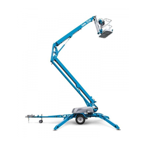
Genie TZ-50 Service Manual
Hide thumbs
Also See for TZ-50:
- Servise manual (168 pages) ,
- Operator's manual (55 pages) ,
- Operator's manual (40 pages)

Related Manuals for Genie TZ-50


Summary of Contents for Genie TZ-50
- Page 1 Service Manual Serial Number Range TZ-50 from TZ5012-254 Part No. 824982 Rev A1 September 2014...
-
Page 2: Introduction
Technical Publications Genie has endeavored to deliver the highest degree of accuracy possible. However, continuous improvement of our products is a Genie policy. Therefore, product specifications are subject to change without notice. Copyright © 2004 Terex Corporation Readers are encouraged to notify Genie of errors 824982 Rev A June 2013 and send in suggestions for improvement. -
Page 3: Revision History
REFERENCE EXAMPLES: Honda Engine_Section 2_Specifications. Electronic Version A-6,B-3,C-7_Section 3_Maintenance Procedure. Click on any procedure or page number 3-2, 6-4, 9-1_Section 4_Repair Procedure. highlighted in blue to view the update. 5-35, 5-56, 5-104_Section 5_Schematic Page #. Part No. 824982 Genie TZ-50... - Page 4 REFERENCE EXAMPLES: Electronic Version Honda Engine_Section 2_Specifications. A-6,B-3,C-7_Section 3_Maintenance Procedure. Click on any procedure or page number 3-2, 6-4, 9-1_Section 4_Repair Procedure. highlighted in blue to view the update. 5-35, 5-56, 5-104_Section 5_Schematic Page #. Genie TZ-50 Part No. 824982...
-
Page 5: Serial Number Legend
September 2014 INTRODUCTION Serial Number Legend Part No. 824982 Genie TZ-50... -
Page 6: Safety Rules
Be sure to wear protective eye wear and other protective clothing if the situation warrants it. Be aware of potential crushing hazards such as moving parts, free swinging or unsecured components when lifting or placing loads. Always wear approved steel-toed shoes. Genie TZ-50 Part No. 824982... - Page 7 Be sure to properly dispose of old oil or other fluids. Use an approved container. Please be environmentally safe. Be sure that your workshop or work area is properly ventilated and well lit. Part No. 824982 Genie TZ-50...
-
Page 8: Table Of Contents
Checklist A Procedures Inspect the Manuals and Decals ..............3 - 6 Perform Pre-operation Inspection ..............3 - 7 Perform Function Tests ................... 3 - 7 Perform Engine Maintenance (if equipped) ............. 3 - 7 Genie TZ-50 Part No. 824982 viii... - Page 9 Check the Wheel Bearings - Mechanical Axle ..........3 - 20 B-10 Service the Hitch - Mechanical Axle .............. 3 - 20 B-11 Perform Axle Maintenance - Mechanical Axle ..........3 - 21 B-12 Perform Engine Maintenance (if equipped) ........... 3 - 22 Part No. 824982 Genie TZ-50...
- Page 10 Check the Turntable Rotation Bearing Bolts ..........3 - 30 Inspect for Turntable Bearing Wear .............. 3 - 31 Checklist E Procedures Test or Replace the Hydraulic Oil ..............3 - 32 Perform Engine Maintenance (if equipped) ........... 3 - 33 Genie TZ-50 Part No. 824982...
- Page 11 Function Manifold Components ..............4 - 30 Jib Manifold Components ................4 - 32 Drive Manifold Components (if equipped) ............. 4 - 34 Valve Adjustments - Function Manifold ............4 - 36 Valve Coils ....................4 - 38 Part No. 824982 Genie TZ-50...
- Page 12 12-2 Outrigger Cylinder ..................4 - 44 Platform Overload Components 13-1 Platform Overload System ................4 - 45 Drive Components 14-1 Drive Motor ....................4 - 47 14-2 Drive Control Box ..................4 - 48 Genie TZ-50 Part No. 824982...
- Page 13 Platform Control Box Wiring Diagram - AS/CE ............5 - 20 Electrical Schematics - ANSI/CSA Electrical Schematic - ANSI/CSA ................5 - 22 Electrical Schematics - AS/CE Electrical Schematic - AS/CE ................. 5 - 28 Hydraulic Schematics Hydraulic Schematic ....................5 - 34 Part No. 824982 Genie TZ-50 xiii...
-
Page 14: Part
September 2014 This page intentionally left blank. Genie TZ-50 Part No. 824982... -
Page 15: Specifications
10 x 3 x 0.75 (including tank) 30 liters For operational specifications, refer to the Operator's Manual. Continuous improvement of our products is a Genie policy. Product specifications are subject to change without notice. Part No. 824982 Genie TZ-50/30 2 - 1... -
Page 16: Performance Specifications
Chevron Rando HD oil is fully compatible and mixable with Shell Donax TG (Dexron III) oils. Secondary boom up 17 to 25 seconds Genie specifications require hydraulic oils which are Secondary boom up 20 to 30 seconds designed to give maximum protection to hydraulic... -
Page 17: Manifold Component Specifications
Note: Genie specifications require additional Primary boom down 1600 psi equipment and special installation instructions for relief valve pressure 110 bar the approved optional fluids. Consult the Genie Service Department before use. Manifold Component Specifications Function pump (models without drive option) Plug torque Type: single section gear pump SAE No. -
Page 18: Machine Torque Specifications
195 ft-lbs 264 Nm Hitch mounting bolts -11 bolts, dry 170 ft-lbs 230 Nm Continuous improvement of our products is a Genie policy. Product specifications are subject to change without notice. 2 - 4 Genie TZ-50/30 Part No. 824982... -
Page 19: Honda Gx160K1 Engine Specifications
Temperature above 50°F / 10°C Use oils meeting API classification SJ as they offer improved wear protection. Units ship with 10W-30 SJ. Continuous improvement of our products is a Genie policy. Product specifications are subject to change without notice. Part No. 824982 Genie TZ-50/30... -
Page 20: Hydraulic Hose And Fitting Torque Specifications
™ SAE Dash size Torque ORFS or 37° JIC fittings and hose ends. Genie specifications require that fittings and hose 14 ft-lbs / 19 Nm ends be torqued to specification when they are 23 ft-lbs / 31.2 Nm removed and installed or when new hoses or fittings are installed. - Page 21 Figure 1 fittings and hose ends are custom-size O-rings. They are not standard SAE size O-rings. They are hex nut available in the O-ring field service kit (Genie part reference mark body hex fitting number 49612). 3 Working clockwise on the body hex fitting, make 2 Lubricate the O-ring before installation.
- Page 22 Section 2 • Specifications September 2014 SPECIFICATIONS 10.9 12.9 2 - 8 Genie TZ-50/30 Part No. 824982...
-
Page 23: Scheduled Maintenance Procedures
Use only Genie approved replacement parts. Indicates that a specific result is expected after Machines that have been out of service for a performing a series of steps. -
Page 24: Pre-Delivery Preparation Report
Make copies of the Maintenance Inspection Report to use for each inspection. Maintain completed forms for a minimum of 4 years or in compliance with employer, jobsite and governmental regulations and requirements. 3 - 2 Genie TZ-50 Part No. 824982... - Page 25 Inspector company Terex South Dakota, Inc USA Genie UK 500 Oak Wood Road The Maltings, Wharf Road PO Box 1150 Grantham, Lincolnshire Watertown, SD 57201-6150 NG31- 6BH England (605) 882-4000 (44) 1476-584333 Part No. 824982 Genie TZ-50 3 - 3...
- Page 26 Section 3 • Scheduled Maintenance Procedures September 2014 This page intentionally left blank. 3 - 4 Genie TZ-50 Part No. 824982...
-
Page 27: Maintenance Inspection Report
After repair, place a check in the “R” box. Legend Y = yes, acceptable N = no, remove from service R = repaired Comments Part No. 824982 Genie TZ-50 3 - 5... -
Page 28: Checklist A Procedures
Carefully and thoroughly Inspect the Manuals and Decals inspect all decals on the machine for legibility and damage. Genie specifications require that this procedure be performed daily or every 8 hours, whichever comes Result: The machine is equipped with all first. -
Page 29: Perform Pre-Operation Inspection
GX160 Engine Owner Manual to the Operator's Manual on your machine. (Honda part number 31ZH7630). Honda GX160 Owner's Manual Genie part number 97228 Perform Function Tests Completing the function tests is essential to safe machine operation. Function tests are designed to discover any malfunctions before the machine is put into service. -
Page 30: Torque The Lug Bolts - Electric And Hydraulic Axles
KNOTT Axle (Dexter part number LIT-001-00). Service Manual (KNOTT part number P005). Dexter Axle Operation Maintenance Service Manual KNOTT Axle Service Manual Genie part number 84376 Genie part number 84443 3 - 8 Genie TZ-50... -
Page 31: Perform Hitch Maintenance - Hydraulic Axle
91 Brake Actuators Owner/Operator Manual Engine Owner Manual (Demco part number BH20023). (Honda part number 31ZH7630). Demco Model 91 Owner/Operator Manual Honda GX160 Owner's Manual Genie part number 84592 Genie part number 97228 Part No. 824982 Genie TZ-50 3 - 9... -
Page 32: Perform 30 Day Service
Inspect the Parking Brake Engine Owner Manual (Honda part number 31ZH7630). • D-3 Replace the Hydraulic Tank Return Filter Honda GX160 Owner's Manual • D-4 Check the Turnable Rotation Genie part number 97228 Bearing Bolts 3 - 10 Genie TZ-50 Part No. 824982... -
Page 33: Grease The Turntable Rotation Bearing And Rotate Gear
Grease the Turntable Rotation Perform Engine Maintenance Bearing and Rotate Gear (if equipped) Genie specifications require that this procedure be Engine specifications require that this procedure be performed every 100 hours of operation. performed every 6 months or every 100 hours, whichever comes first. -
Page 34: Checklist B Procedures
1 Put on protective clothing and eye wear. 2 Be sure that the battery cable connections are 8 Inspect the battery charger plug and pigtail for free of corrosion. damage or excessive insulation wear. Replace as required. 3 - 12 Genie TZ-50 Part No. 824982... -
Page 35: Inspect The Electrical Wiring
2 Turn the key switch to ground control and pull Note: If you have any further questions regarding out the red Emergency Stop button to the on the battery charger operation, please contact Genie position at both the ground and platform Product Support. -
Page 36: Test The Manual Override
Testing the manual override for malfunctions is essential for safe machine operation. An unsafe working condition exists if the manual override Genie requires that this procedure be performed function does not operate in the event of a main every 250 hours or quarterly, whichever comes power loss. - Page 37 Note: The valve spool must be reset for the primary Note: The valve spool must be reset for the boom up function to operate from the machine secondary boom down function to operate from the controls. machine controls. Part No. 824982 Genie TZ-50 3 - 15...
-
Page 38: Perform Hydraulic Oil Analysis
14 Release the red thumbscrew at the center of the valve stem, to reset the valve. Note: The valve spool must be reset for the turntable rotate function to operate from the machine controls. 3 - 16 Genie TZ-50 Part No. 824982... -
Page 39: Perform Axle Maintenance - Electric And Hydraulic Axles
1 Remove the cap from the top of the jack housing and, using automotive grease, lightly Dexter Axle Operation Maintenance Service Manual grease the internal gears. Rotate the handle to Genie part number 84376 evenly distribute the lubricant to the internal gears. -
Page 40: Inspect The Parking Brake
5 through 8 until the adjustment is correct brake cables are too loose, the brakes will not OR see B-8, Perform Axle Maintenance - activate when the lever is set. Electric and Hydraulic Axles 3 - 18 Genie TZ-50 Part No. 824982... - Page 41 10 Adjust the wheel brakes until the wheel turns freely. Note: Slight rubbing noises, which do not affect the free turning of the wheel, are permitted. 11 Repeat steps 9 and 10 for the other wheel. Part No. 824982 Genie TZ-50 3 - 19...
-
Page 42: Check The Wheel Bearings - Mechanical Axle
See C-5, Grease the Axle Wheel Bearings - Mechanical Axle. Required maintenance procedures and additional axle information is available in the KNOTT Axle Service Manual (KNOTT part number P005). KNOTT Axle Service Manual Genie part number 84443 3 - 20 Genie TZ-50 Part No. 824982... -
Page 43: Perform Axle Maintenance - Mechanical Axle
Required maintenance procedures and additional Service Manual (KNOTT part number P005). axle information is available in the KNOTT Axle Service Manual (KNOTT part number P005). KNOTT Axle Service Manual Genie part number 84443 KNOTT Axle Service Manual Genie part number 84443 Part No. -
Page 44: B-12 Perform Engine Maintenance (If Equipped)
Honda GX160 Engine Owner Manual (Honda part number 31ZH7630) and the Honda GX160 Engine Shop Manual (Honda part number 61ZH700). Honda GX160 Owner's Manual Genie part number 97228 Honda GX160 Shop Manual Genie part number 97229... -
Page 45: Checklist C Procedures
Test the Platform Overload Mechanism (if equipped) System (if equipped) Genie specifications require that this procedure be Genie specifications require that this procedure be performed every 500 hours or 6 months, whichever performed every 500 hours or 6 months, whichever comes first. -
Page 46: Perform Axle Maintenance - Electric And Hydraulic Axles
(Dexter part number LIT-001-00). suitable lifting device. Result: The platform overload indicator light Dexter Axle Operation Maintenance Service Manual Genie part number 84376 should turn off at both the ground and platform controls. 12 Test all machine functions from the ground controls. -
Page 47: Replace The Hydraulic Tank Breather Cap - Models With Optional Hydraulic Oil
4 Remove, wash and inspect the axle wheel bearings and spacer ring. 5 Pack both bearings with clean, fresh grease. 6 Install the bearings and spacer ring onto the axle and reassemble the axle. Part No. 824982 Genie TZ-50 3 - 25... -
Page 48: Adjust The Brakes - Mechanical Axle
Service Manual (KNOTT part number P005). 2 Release the parking brake. KNOTT Axle Service Manual 3 Working from the exposed inside face of the Genie part number 84443 brake plate, opposite the cable entry, tighten the adjusting screw until the wheel can only be turned with difficulty or not at all. - Page 49 Required maintenance procedures and additional axle information is available in the KNOTT Axle Service Manual (KNOTT part number P005). KNOTT Axle Service Manual Genie part number 84443 Part No. 824982 Genie TZ-50 3 - 27...
-
Page 50: Checklist D Procedures
3 Extend and retract the boom through the entire range of motion to check for tight spots that Dexter Axle Operation Maintenance Service Manual may cause binding or scraping of the boom. Genie part number 84376 Note: Always maintain squareness between the outer and inner boom tubes. -
Page 51: Replace The Hydraulic Tank Return Filter
Bodily injury hazard. Spraying hydraulic oil can penetrate and burn skin. Loosen hydraulic connections very slowly to allow the oil pressure to dissipate gradually. Do not allow oil to squirt or spray. Part No. 824982 Genie TZ-50 3 - 29... -
Page 52: Check The Turntable Rotation Bearing Bolts
Bearing-to-chassis bolt torque sequence Turntable rotation bearing bolt torque specifications Bearing to chassis, lubricated 195 ft-lbs 264 Nm Bearing to swing chassis, lubricated 195 ft-lbs 264 Nm Illustration 1 Bearing-to-swing chassis bolt torque sequence 3 - 30 Genie TZ-50 Part No. 824982... -
Page 53: Inspect For Turntable Bearing Wear
90° apart. 11 Lower the primary and secondary booms to the stowed position and turn the machine off. 12 Remove the dial indicator from the machine. Part No. 824982 Genie TZ-50 3 - 31... -
Page 54: Checklist E Procedures
Hydraulic tank drain plug, dry 150 in-lbs result in death or serious injury. 16.9 Nm Remove all rings, watches and other jewelry. Hydraulic tank drain plug, lubricated 112 in-lbs 12.6 Nm 3 - 32 Genie TZ-50 Part No. 824982... -
Page 55: Perform Engine Maintenance (If Equipped)
Do not over tighten. Honda GX160 Shop Manual 13 Install the hydraulic lines into the filter head. Genie part number 97229 14 Connect the battery pack to the machine. 15 Fill the hydraulic tank with hydraulic oil until the fluid is at the mark on the tank. - Page 56 Section 3 • Scheduled Maintenance Procedures September 2014 This page intentionally left blank. 3 - 34 Genie TZ-50 Part No. 824982...
-
Page 57: Repair Procedures
Genie result in death or serious injury. TZ-50 Operator's Manual on your machine. Indicates a potentially hazardous Be sure that all necessary tools and parts are situation which, if not avoided, available and ready for use. -
Page 58: Platform Components
Do not allow oil to squirt or spray. 6 Attach a lifting strap of suitable capacity from an overhead crane to the platform mount. Support the mount. Do not apply any lifting pressure. 4 - 2 Genie TZ-50 Part No. 824982... - Page 59 2 Activate the platform rotate left function and supported when the pivot pin is rotate the platform completely to the left. removed. Continue to activate the rotate left function for 3 seconds. Part No. 824982 Genie TZ-50 4 - 3...
-
Page 60: Jib Boom Components
Bodily injury hazard. Spraying hydraulic oil can penetrate and burn skin. Loosen hydraulic connections very slowly to allow the oil pressure to dissipate gradually. Do not allow oil to squirt or spray. 4 - 4 Genie TZ-50 Part No. 824982... - Page 61 24 Attach a lifting strap of suitable capacity from an overhead crane to the jib mount. Support the Component damage hazard. mount. Do not apply any lifting pressure. Cables and hoses can be damaged if they are kinked or pinched. Part No. 824982 Genie TZ-50 4 - 5...
-
Page 62: Jib Boom Lift Cylinder
Do not apply any lifting pressure. 5 Attach a lifting strap of suitable capacity from an overhead crane to the jib boom. Support the jib boom. Do not apply any lifting pressure. 4 - 6 Genie TZ-50 Part No. 824982... - Page 63 Remove the cylinder from the machine. Crushing hazard. The jib cylinder could fall if not properly supported when the pivot pin is removed. Part No. 824982 Genie TZ-50 4 - 7...
-
Page 64: Primary Boom Components
(located behind ground control box) extension boom turntable platform level slave cylinder secondary boom pivot pin 4 - 8 Genie TZ-50 Part No. 824982... -
Page 65: Cable Track
Crushing hazard. If the cable bridge and the cable track are not properly secured together, the combination could become unbalanced and fall when removed from the machine. Part No. 824982 Genie TZ-50 4 - 9... - Page 66 Crushing hazard. The cable track of the new section of cable track. could become unbalanced and fall if not properly attached to the overhead crane. 4 - 10 Genie TZ-50 Part No. 824982...
-
Page 67: Primary Boom
Cables and hoses can be damaged if they are kinked or pinched. For ease of assembly, pay close attention to how the cables are routed when pulling the cables to the mid pivot. Part No. 824982 Genie TZ-50 4 - 11... - Page 68 Crushing hazard. The primary boom could become unbalanced 9 Remove the pin retaining fastener from the and fall if not properly supported primary lift cylinder rod end pivot pin. when removed from the machine. 4 - 12 Genie TZ-50 Part No. 824982...
- Page 69 6 Remove the fasteners and hose clamp securing boom extension cylinder rod-end pivot pins. the platform level slave cylinder hoses to the extension boom. 19 Remove the primary boom extension cylinder from the boom extension. Part No. 824982 Genie TZ-50 4 - 13...
-
Page 70: Primary Boom Lift Cylinder
4 Using a soft metal drift, remove the lift cylinder rod end pivot pin. Crushing hazard. The cylinder will fall if not properly supported when the pivot pin is removed. 4 - 14 Genie TZ-50 Part No. 824982... -
Page 71: Platform Leveling Cylinders
Do not allow oil to squirt or spray. Part No. 824982 Genie TZ-50 4 - 15... - Page 72 It is part of the closed loop hydraulic squirt or spray. circuit that keeps the platform level through the entire range of boom motion. The master cylinder is located inside the mid pivot. 4 - 16 Genie TZ-50 Part No. 824982...
- Page 73 September 2014 Section 4 • Repair Procedures This page intentionally left blank. Part No. 824982 Genie TZ-50 4 - 17...
-
Page 74: Secondary Boom Components
(located behind ground control box) extension boom turntable platform level slave cylinder secondary boom pivot pin 4 - 18 Genie TZ-50 Part No. 824982... -
Page 75: Secondary Boom
Raise the cylinder to a horizontal pin is removed. position. Part No. 824982 Genie TZ-50 4 - 19... - Page 76 27 Attach a lifting strap of suitable capacity from an overhead crane to the rod end of the lift cylinder. Raise the cylinder slightly, remove the block and lower the cylinder through the secondary link and onto the front bulkhead. 4 - 20 Genie TZ-50 Part No. 824982...
-
Page 77: Secondary Boom Lift Cylinder
9 Rotate the rod end of the secondary boom lift cylinder approximately 90°. 10 Raise the cylinder slightly, remove the block and lower the cylinder through the secondary link and onto the front bulkhead. Part No. 824982 Genie TZ-50 4 - 21... - Page 78 14 Carefully remove the cylinder from the machine. Crushing hazard. The lift cylinder could become unbalanced and fall if not properly supported when removed from the machine. 4 - 22 Genie TZ-50 Part No. 824982...
-
Page 79: Engine
Honda GX160 Engine Owner Manual (Honda part number 31ZH7630) OR the Honda Engines Shop Manual (Honda part number 61ZH700). Honda GX160 Owner's Manual Genie part number 97228 Honda Engines Shop Manual Genie part number 97229 5 amp fuse - starter circuit (inside cover) -
Page 80: Ground Controls
2 Turn the key switch to ground control and pull fasteners. Remove the level sensor from the out the red Emergency Stop buttons to the on machine. position at both the ground and platform controls. 4 - 24 Genie TZ-50 Part No. 824982... - Page 81 Result: The tilt sensor alarm should not sound. Result: The tilt alarm will sound at 180 beeps per minute. The level sensor is faulty and must be replaced. Repeat this procedure beginning with step 6. Part No. 824982 Genie TZ-50 4 - 25...
- Page 82 Result: The tilt alarm does not sound. The level sensor is faulty and must be replaced. Repeat this procedure beginning with step 6. 24 Return the outriggers to the stowed position. 4 - 26 Genie TZ-50 Part No. 824982...
- Page 83 Result: The outriggers will lower and adjust to level the machine and raise the wheels off the ground. Use the bubble level located below the ground controls to confirm that the machine is level. Part No. 824982 Genie TZ-50 4 - 27...
-
Page 84: Hydraulic Pump
3 Turn the key switch to ground control and pull gradually. Do not allow oil to squirt out the red Emergency Stop button to the on or spray. position at both the ground and platform controls. 4 - 28 Genie TZ-50 Part No. 824982... - Page 85 Bodily injury hazard. Spraying hydraulic oil can penetrate and burn skin. Loosen hydraulic connections very slowly to allow the oil pressure to dissipate gradually. Do not allow oil to squirt or spray. Part No. 824982 Genie TZ-50 4 - 29...
-
Page 86: Function Manifold Components
Orifice - plug, 0.080 inch / 2 mm ... Q ..Restricts platform down fluid flow — Port plug ........................97-117 in-lbs / 11-13 Nm Solenoid valve, 3 position 4 way with manual override ......R ..Turntable rotate left/right ..... 18-20 ft-lbs / 25-27 Nm 4 - 30 Genie TZ-50 Part No. 824982... - Page 87 September 2014 Section 4 • Repair Procedures MANIFOLDS Note: 'alpha-numeric' callouts refer to corresponding notes on the electrical schematic Note: 'alpha' callouts refer to corresponding notes on the hydraulic schematic Part No. 824982 Genie TZ-50 4 - 31...
-
Page 88: Jib Manifold Components
Orifice - plug, 0.040 inch / 1 mm ... AJ ..Jib boom down circuit — Port plug ........................97-117 in-lbs / 11-13 Nm Shuttle valve, 2 position 3 way .... AK ..Platform level circuit ........4-5 ft-lbs / 6 Nm 4 - 32 Genie TZ-50 Part No. 824982... - Page 89 Section 4 • Repair Procedures MANIFOLDS Models with Platform Rotate Note: 'alpha' callouts refer to corresponding notes on the hydraulic schematic Note: 'alpha-numeric' callouts refer to corresponding notes on the electrical schematic Models without Platform Rotate Part No. 824982 Genie TZ-50 4 - 33...
-
Page 90: Drive Manifold Components (If Equipped)
Solenoid valve, 2 position 4 way ..BN ..Drive circuit, left side ......18-20 ft-lbs / 25-27 Nm Proportional valve, 2 position 2 way ... BO ..Drive circuit, left side ......18-20 ft-lbs / 25-27 Nm 4 - 34 Genie TZ-50 Part No. 824982... - Page 91 MANIFOLDS Note: 'alpha-numeric' callouts refer to corresponding notes on the electrical schematic Note: 'alpha' callouts refer to corresponding notes on the hydraulic schematic Y50A After Before Serial Number Serial Number TZ5004-152 TZ5004-151 Part No. 824982 Genie TZ-50 4 - 35...
-
Page 92: Valve Adjustments - Function Manifold
6 Repeat step 3 to confirm the relief valve 7 Repeat step 4 to confirm the relief valve pressure. pressure. 4 - 36 Genie TZ-50 Part No. 824982... - Page 93 Begin timing when the turntable begins to rotate. 9 Continue rotating the turntable and note the time when the machine stops rotating at 359°. Refer to Section 2, Specifications . Part No. 824982 Genie TZ-50 4 - 37...
-
Page 94: Valve Coils
Solenoid valve, 2 position 2 way N.C.29 to 31W specification, plus or minus 30%. 24V DC with diode Result: If the resistance is not within (schematic items CA, CB, CC and CD) specification, plus or minus 30%, replace the coil. 4 - 38 Genie TZ-50 Part No. 824982... - Page 95 How to Test a Coil Diode 3 Set a multimeter to read DC amperage. Note: The multimeter, when set to read DC Genie incorporates spike-suppressing diodes in all amperage, should be capable of reading up to 800 of its coils. Properly functioning coil diodes protect the electrical circuit by suppressing voltage spikes.
-
Page 96: Hydraulic Tank
Bodily injury hazard. Spraying hydraulic oil can penetrate and burn skin. Loosen hydraulic connections very slowly to allow the oil pressure to dissipate gradually. Do not allow oil to squirt or spray. 4 - 40 Genie TZ-50 Part No. 824982... -
Page 97: Axle Components
Note: When the axle is installed, the brakes should be bled. Refer to the appropriate brake manufacturer's manual that was shipped with your primary brake cable Genie TZ-50. tension equalizer secondary brake cables Part No. 824982 Genie TZ-50... -
Page 98: Trailer Components
(Dexter part number LIT-001-00). available in the Dexter Axle Operation Maintenance Service Manual (Dexter part number LIT-001-00). Dexter Axle Operation Maintenance Service Manual Genie part number 84376 Dexter Axle Operation Maintenance Service Manual Genie part number 84376 2 Chock the wheels. -
Page 99: Outrigger Components
6 Attach a lifting strap of suitable capacity from an overhead crane to the rod end of the outrigger cylinder. Support the cylinder. Do not apply any lifting pressure. Part No. 824982 Genie TZ-50 4 - 43... -
Page 100: Outrigger Cylinder
Bodily injury hazard. Spraying hydraulic oil can penetrate and burn skin. Loosen hydraulic connections very slowly to allow the oil pressure to dissipate gradually. Do not allow oil to squirt or spray. 4 - 44 Genie TZ-50 Part No. 824982... -
Page 101: Platform Overload Components
6 Using a suitable lifting device, place an switch wires. Securely install the wires onto the appropriate test weight equal to that of the limit switch. maximum platform capacity at the center of the platform floor. Part No. 824982 Genie TZ-50 4 - 45... - Page 102 Result: All platform control functions should not operate. 16 Turn the key switch to ground control. 17 Test all machine functions from the ground controls. Result: All ground control functions should not operate. 4 - 46 Genie TZ-50 Part No. 824982...
-
Page 103: Drive Components
September 2014 Section 4 • Repair Procedures Drive Components The TZ-50 drive option allows the operator to move 14-1 Drive Motor the machine into another position without having to How to Remove a Drive Motor use a tow vehicle to do so. This option package... -
Page 104: Drive Control Box
Keeping the drive controls clean and defect free is drive controls circuit board essential to safe machine operation. For further 14-wire main cable information or assistance, consult the Genie 4 Tag and disconnect the circuit board from the Industries Service Department. 14-wire main cable. -
Page 105: Hydraulic Schematics
Identify Malfunction Troubleshoot Be sure that all necessary tools and test symptoms discovered equipment are available and ready for use. problem still exists Inspect Perform Return to and test repair service problem solved Part No. 824982 TZ-50 5 - 1... -
Page 106: Electrical Abbreviations Legend
Level sensor (auto level) BN65 Boom extend/retract CR67 Primary boom BN66 Turntable rotate CR68 Secondary boom BN67 Platform level up/down CR69 Boom extend/retract BN68 Engine start CR70 Turntable rotate BN90 Choke BN93 Platform rotate 5 - 2 TZ-50 Part No. 824982... - Page 107 NCHO Normally closed, held open Joystick N.O. Normally Open Keyswitch NOHC Normally open, held closed Power switch Emergency Stop button at ground controls Emergency Stop button at plat. controls Emergency Stop button at drive controls Choke Solenoid Part No. 824982 TZ-50 5 - 3...
- Page 108 Outrigger retract Outrigger extend Drive forward/reverse left Y50A Drive forward/reverse right Secondary down Secondary up Proportional drive right Proportional drive left Jib boom retract Jib boom extend Platform rotate left Platform rotate right 5 - 4 TZ-50 Part No. 824982...
-
Page 109: Limit Switch Legend
September 2014 Section 5 • Schematics Limit Switch Legend Item Description Schematic Boom limit switches LS18 / LS18A Outrigger limit switch LS12/LS13/LS14/LS15 Part No. 824982 TZ-50 5 - 5... -
Page 110: Electrical Symbols Legend
Key switch Hour meter EMERGENCY STOP Emergency stop button, Motor controller normally closed Alarm Circuit breaker Battery charger Solenoid valve with diode N.C.H.O. N.O.H.C. N.C. Limit switch Quick disconnect Level sensor Toggle switch 5 - 6 TZ-50 Part No. 824982... - Page 111 Platform level counterbalance Pilot operated relief valve Orifice - platform rotate speed Orifice - jib boom up speed Orifice - jib boom down and platform level speed Shuttle valve - platform level circuit Part No. 824982 TZ-50 5 - 7...
-
Page 112: Hydraulic Symbols Legend
2 position 2 way directional valve with proportional valve manual override normally closed Solenoid operated Double acting cylinder Solenoid operated 3 position 4 way 3 position 4 way directional valve directional valve with manual override 5 - 8 TZ-50 Part No. 824982... -
Page 113: Honda Gx160 Engine Wiring Diagram
Section 5 • Schematics Honda GX160 Engine Wiring Diagram BATTERY STARTER SOLENOID BK/WH CONTROL BOX 5A FUSE ENGINE CIRCUIT BREAKER SWITCH RECTIFIER BK/RD OIL LEVEL TRANSISTORIZED SWITCH IGNITION UNIT CHARGING COIL SPARK PLUG Part No. 824982 TZ-50 5 - 9... -
Page 114: Trailer Lighting Wiring Diagram - Ansi / Csa
Trailer Lighting Wiring Diagram - ANSI / CSA RIGHT SIDE MARKER QD12 TRAILER PLUG BN/YL RIGHT REAR TAIL LIGHT 1 GN 2 YL 3 BN/YL LEFT SIDE MARKER 3 BN LEFT REAR 4 WH TAIL LIGHT 5 - 10 TZ-50 Part No. 824982... -
Page 115: Trailer Lighting Wiring Diagram - Mechanical Axle, Ce
7 BK 8 WH/BK LEFT SIDE MARKER TURN BACKUP RIGHT REAR TAIL LIGHT LEFT REAR TAIL LIGHT LEFT REAR TAIL LIGHT SIDE MARKER TURN SIGNAL FOG LIGHT RED REFLECTOR REVERSE LIGHT BRAKE LIGHT Part No. 824982 TZ-50 5 - 11... -
Page 116: Trailer Lighting Wiring Diagram - Electric Axle, As
Platform Wiring Harness TURN STOP STOP TURN LEFT SIDE MARKER LEFT REAR TAIL LIGHT RIGHT REAR TAIL LIGHT BACKUP LEFT REAR TAIL LIGHT SIDE MARKER TURN SIGNAL FOG LIGHT RED REFLECTOR REVERSE LIGHT BRAKE LIGHT 5 - 12 TZ-50 Part No. 824982... -
Page 117: Trailer Lighting Wiring Diagram - Hydraulic Axle, As
7 BK 8 WH/BK LEFT SIDE MARKER TURN BACKUP RIGHT REAR TAIL LIGHT LEFT REAR TAIL LIGHT LEFT REAR TAIL LIGHT SIDE MARKER TURN SIGNAL FOG LIGHT RED REFLECTOR REVERSE LIGHT BRAKE LIGHT Part No. 824982 TZ-50 5 - 13... -
Page 118: Ground Control Box Wiring Diagram - Ansi/Csa
RIGHT FRONT RD/WH P5-3 UP/DOWN OUTRIGGER RF LED OR/WH TB21 OR/WH P5-5 TB11 WH/BK TB31 GN/WH TB30 BL/BK TB25 RD/BK TB26 TB29 CR78A TERMINAL 87A BK/WH TB27 TB32 ALARM HOUR METER TB35 ES0440G 5 - 14 TZ-50 Part No. 824982... - Page 119 WH/BK TURNTABLE HARNESS TB16 HARNESS CR86 CR75 PIN C LEVEL SENSOR SEQUENCING TB35 NOTE: DIODES ARE 2 AMP 1000 OHM UNLESS OTHERWISE MARKED P3-X 200 OHM BATTERY CHARGE ES0440G INDICATOR TB35 P1 (E-STOP) Part No. 824982 TZ-50 5 - 15...
-
Page 120: Platform Control Box Wiring Diagram - Ansi/Csa
CR71 OR/BK JIB HARNESS PIN PLATFORM LEVEL P1-6 JIB HARNESS PIN BN97 GN/BK G7 “+” JIB HARNESS PIN JIB BOOM UP/DOWN GN/WH JIB HARNESS PIN CR87 BL/BK JIB HARNESS PIN PLATFORM ROTATE ES0440G 5 - 16 TZ-50 Part No. 824982... - Page 121 September 2014 Section 5 • Schematics This page intentionally left blank. Part No. 824982 TZ-50 5 - 17...
-
Page 122: Ground Control Box Wiring Diagram - As/Ce
RIGHT FRONT RD/WH PB5-3 UP/DOWN OUTRIGGER RF LED OR/WH TB21 OR/WH PB5-5 TB11 WH/BK TB31 GN/WH TB30 BL/BK TB25 RD/BK TB26 TB29 CR78A TERMINAL 87A BK/WH TB27 TB32 ALARM HOUR METER TB35 ES0440G 5 - 18 TZ-50 Part No. 824982... - Page 123 WH/BK TURNTABLE HARNESS TB16 HARNESS CR75 CR86 PIN P3-C LEVEL SENSOR SEQUENCING TB35 NOTE: DIODES ARE 2 AMP 1000 OHM BATTERY CHARGE UNLESS OTHERWISE MARKED INDICATOR TB35 P3-X 200 OHM P1 (E-STOP) ES0440G Part No. 824982 TZ-50 5 - 19...
-
Page 124: Platform Control Box Wiring Diagram - As/Ce
CR71 OR/BK JIB HARNESS PIN PLATFORM LEVEL JIB HARNESS PIN BN97 G7 “+” GN/BK JIB HARNESS PIN JIB BOOM UP/DOWN GN/WH JIB HARNESS PIN CR87 BL/BK JIB HARNESS PIN PLATFORM ROTATE (OPTION) ES0440G 5 - 20 TZ-50 Part No. 824982... -
Page 125: Electrical Schematic - Ansi/Csa
Section 5 • Schematics September 2014 Electrical Schematic - ANSI/CSA 5 - 22 5 - 21... - Page 126 (17) CR75 CR75 LOAD GCON GROUND CR20 OUTRIGGER LIMIT SWITCHES ODR1 BATTERY 24V 275AMP. U6-B+ ALTERNATOR 50AMP. P8-1 P8-3 50 AMP. EXCT. BAT. BAT. STA. CHARGER REGULATOR IND. BATTERY GROUND ES0440G ENGINE OPTION 5 - 22 TZ-50 Part No. 824982...
- Page 127 (14) (18) CR72 TB35 (18) (10) (10) GCON GROUND GCON GROUND BATTERY 24V 47 mH, 2.5 AMP, 0.034 OHM Y50A MOTOR CONTROLLER GCON GROUND UB-6+ M5 MOTOR (HARNESS GROUND PLUG) BATTERY GROUND ES0440G Part No. 824982 TZ-50 5 - 23...
- Page 128 September 2014 Section 5 • Schematics Electrical Schematic - ANSI/CSA 5 - 23 5 - 24...
- Page 129 U16A CR70 CR68 CR67 CR69 (11) (12) (13) (14) LOAD GCON GROUND ES0440G LS13 LS15 RF O/R RR O/R LS12 LS14 LF O/R LR O/R OUTRIGGER LIMIT SWITCHES GCON GROUND (HARNESS GROUND PLUG) Part No. 824982 TZ-50 5 - 25...
- Page 130 September 2014 Section 5 • Schematics Electrical Schematic - ANSI/CSA 5 - 25 5 - 26...
-
Page 131: Electrical Schematic - As/Ce
Section 5 • Schematics September 2014 Electrical Schematic - AS/CE 5 - 28 5 - 27... - Page 132 (17) CR75 CR75 LOAD GCON GROUND CR20 OUTRIGGER LIMIT SWITCHES ODR1 BATTERY 24V 275AMP. U6-B+ 50AMP. ALTERNATOR P8-1 P8-3 50 AMP. EXCT. BAT. BAT. STA. CHARGER REGULATOR IND. BATTERY GROUND ES0440G ENGINE OPTION 5 - 28 TZ-50 Part No. 824982...
- Page 133 (14) (18) CR72 TB35 (18) (10) (10) GCON GROUND GCON GROUND BATTERY 24V 47 mH, 2.5 AMP, 0.034 OHM Y50A MOTOR CONTROLLER GCON GROUND M5 MOTOR UB-6+ (HARNESS GROUND PLUG) BATTERY GROUND ES0440G Part No. 824982 TZ-50 5 - 29...
- Page 134 September 2014 Section 5 • Schematics Electrical Schematic - AS/CE 5 - 29 5 - 30...
- Page 135 U16A CR70 CR68 CR67 CR69 (11) (12) (13) (14) LOAD GCON GROUND ES0440G LS13 LS15 RF O/R RR O/R LS12 LS14 LF O/R LR O/R OUTRIGGER LIMIT SWITCHES GCON GROUND (HARNESS GROUND PLUG) Part No. 824982 TZ-50 5 - 31...
- Page 136 September 2014 Section 5 • Schematics Electrical Schematic - AS/CE 5 - 31 5 - 32...
-
Page 137: Hydraulic Schematic
Section 5 • Schematics September 2014 Hydraulic Schematic 5 - 34 5 - 33... - Page 138 2.8 gpm POWER UNIT 2.8 gpm DRIVE OPTION 10.6 L/min MANIFOLD MANIFOLD 10.6 L/min SEC 2 SEC 1 HYDRAULIC TANK HSTZ50 G MODELS WITHOUT PLATFORM ROTATE MODELS WITH PLATFORM ROTATE MODELS WITHOUT DRIVE OPTION 5 - 34 TZ-50 Part No. 824982...
Need help?
Do you have a question about the TZ-50 and is the answer not in the manual?
Questions and answers
What is wrong if my TMZ 50 doesn't display any lights? Acts like it is dead
If your Genie TZ-50 does not display any lights and appears to be dead, a possible issue could be a faulty or activated emergency stop switch, as it cuts power to the system. Check if the emergency stop button is engaged and reset it if necessary. Other possible causes include a disconnected or faulty wire harness, a failed control box, or a drained battery.
This answer is automatically generated