Omnex T150 Installation And Configuration Manual
Omnex generic 6sw portable, long range, programmable radio remote control system
Hide thumbs
Also See for T150:
- Installation/configuration manual (16 pages) ,
- Installation and configuration manual (16 pages) ,
- User manual (4 pages)
Table of Contents
Advertisement
GENERIC 6SW
Installation / Configuration Manual
T150 Transmitter
R130 Receiver
Revised May 23, 2006
Version 2
DMAN - xxxx - xx
#74-1833 Coast Meridian Road, Port Coquitlam, BC, Canada • V3C 6G5
Ph# (604) 944-9247 • Fax# (604) 944-9267
Toll Free 1-800-663-8806
www.omnexcontrols.com
call toll free: 1-800-663-8806
DMAN-xxxx-xx (Rev x.x)
Advertisement
Table of Contents

Related Manuals for Omnex T150


Summary of Contents for Omnex T150
- Page 1 GENERIC 6SW Installation / Configuration Manual T150 Transmitter R130 Receiver Revised May 23, 2006 Version 2 DMAN - xxxx - xx #74-1833 Coast Meridian Road, Port Coquitlam, BC, Canada • V3C 6G5 Ph# (604) 944-9247 • Fax# (604) 944-9267 Toll Free 1-800-663-8806 www.omnexcontrols.com...
-
Page 2: Table Of Contents
Table of Contents System Overview ............................3 Features ............................... 3 T150 Dimensions and Controls........................3 Installing the Receiver..........................4 Anti 2 Block Wiring ............................5 Installation Considerations ........................... 5 Power the Transmitter..........................6 Test the Transmitter / Receiver Link ......................6 Download ID Code ............................ -
Page 3: System Overview
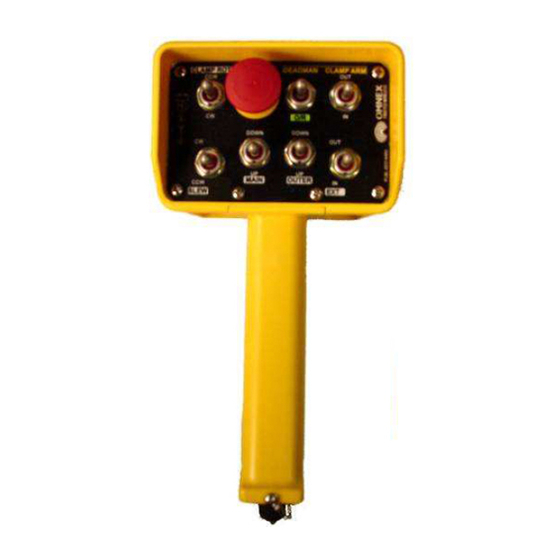
The T150 transmitter comes with 4 to 6 switches and an optional proportional trigger control. It uses standard, long lasting AA batteries. Each T150 transmitter uses a unique ID code to ensure that no two systems will conflict at a job site. -
Page 4: Installing The Receiver
R130 Output Cables can be provided with every system to simplify the wiring process. The Wire # column below only applies to the OMNEX Output Cable configuration. Tips on mounting, power connections and filtering are also provided under Installation Considerations. -
Page 5: Anti 2 Block Wiring
The FCC and ISC require that the antenna be restricted to that supplied by the manufacturer and approved for use with this product. An op- tional 0dB coax wire antenna may be supplied. For other antenna options, please contact OMNEX Control Systems ULC Mounting and Installation The receiver can be mounted by fastening two ¼”... -
Page 6: Power The Transmitter
2. Power the R130 1. Press [E-Stop] FAULT LINK ESTOP STATUS 3. Power the T150 If the (Active) light on the trans- mitter is flashing and the (Link) light on the receiver is flashing GREEN, a link between the two exists. -
Page 7: Download Id Code
A. Press [E-Stop] B. Twist clockwise & release [E- Stop] C. Supply power to the receiver 3. Power T150 into Configuration Mode A. Hold [SW-5] switch UP B. Press [E-Stop] C. Twist clockwise & release [E-Stop] D. Release [SW-5] Switch... - Page 8 Download ID Code (Use in case of Link Test failure) 4. Put R130 into Setup Mode ESTOP FAULT LINK STATUS ESTOP FAULT LINK STATUS A. Press & hold [Setup] button until (Status) light goes from slow flash to fast flash Setup Setup B.
-
Page 9: Calibrating Proportional Controls
1. Prepare T150, Power R130 ESTOP FAULT LINK STATUS A. Press [E-Stop] B. Twist clockwise & Release [E-Stop] C. Supply power to the receiver 2. Power T150 into Configuration Mode A. Hold [SW-5] switch DOWN B. Press [E-Stop] C. Twist clockwise & release [E-Stop] D. -
Page 10: Diagnostics-T150 Transmitter
Diagnostics—T150 Transmitter Tether connection detected Low battery. Unit will run approximately 10 hours after Battery light starts flashing. Flashing rapidly for 10 seconds indicates a transmitter failure. Normal Operation The Active light will flash several times per second, indicating that the transmitter is sending signals to the receiver. -
Page 11: Diagnostics-R130 Receiver
Diagnostics - R130 Receiver Normal Operation ESTOP FAULT LINK STATUS Transmitter is OFF If the transmitter is off, the receiver is operating properly. ESTOP FAULT LINK STATUS Transmitter is ON When the transmitter is turned on, the Link light (fast flashing) and E-Stop (GREEN) indicates the receiver is operating properly. -
Page 12: Troubleshooting Guide
Troubleshooting Guide Chart #1 Test the Receiver—R130 OK state: Status—GREEN Start Link—RED Initial Condition: What is the state E-Stop—RED Turn transmitter off (all lights are off—press the of the lights on Fault—OFF OFF button) the receiver? Cycle power to receiver (turn off and back on) Note: If there is a short to ground on an output, it is not indicated at this stage. - Page 13 Troubleshooting Guide (con’t) Chart #2 Test the Transmitter—T150 Turn off the receiver Ensure there are good batteries in the transmitter Turn on the transmitter OK state: Active light—steady for Activate a about 3 seconds then What is the state of goes to fast flash.
- Page 14 Troubleshooting Guide (con’t) Chart #3 Testing the Transmitter / Receiver Communication Transmitter: Transmitter: Active light is flashing Active light is flashing Receiver: What is the status of Receiver: Status—GREEN the lights of both the Status—GREEN Link—RED transmitter and Link—Flashing GREEN Fault—OFF receiver? Fault—OFF...
- Page 15 Troubleshooting Guide Chart #4 Considerations when Downloading the ID Potential downloading issues If testing of the receiver and transmitter both show the system as working (Chart 1 & 2), then the transmitter and receiver will both go into Download/Configuration mode. Possible issues could arise during Step 4, the download phase of reprogramming.
-
Page 16: Parts & Accessories
OMNEX's entire liability and your exclusive remedy shall be, at OM- V3C 6G5 (2) this device must accept any NEX's option, either the (a) repair or (b) replacement of the OMNEX product interference received, including...
Need help?
Do you have a question about the T150 and is the answer not in the manual?
Questions and answers