Table of Contents
Advertisement
GENERIC
Installation / Configuration Manual
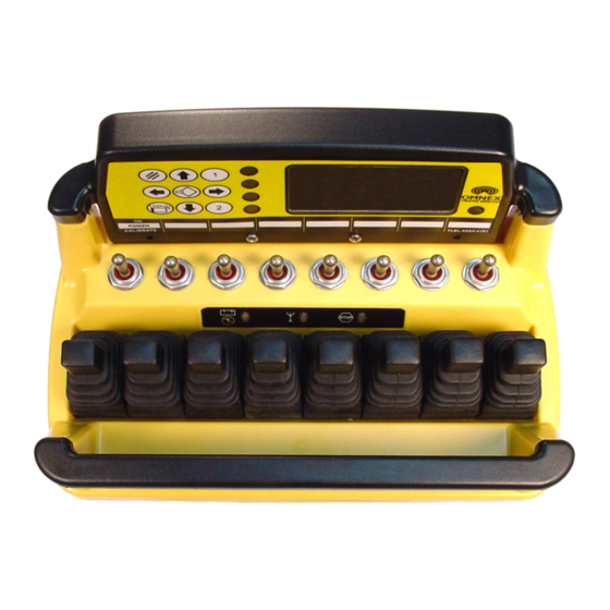
T2300 Transmitter
R2160 Receiver
D180 Expansion Module
Revised February 9, 200
Version 3
DMAN - xxxx - xx
#74-1833 Coast Meridian Road, Port Coquitlam, BC, Canada • V3C 6G5
Ph# (604) 944-9247 • Fax# (604) 944-9267
Toll Free 1-800-663-8806
call toll free: 1-800-663-8806
www.omnexcontrols.com
DMAN-xxxx-xx
1
Advertisement
Table of Contents

Related Manuals for Omnex T2300


Summary of Contents for Omnex T2300
- Page 1 GENERIC Installation / Configuration Manual T2300 Transmitter R2160 Receiver D180 Expansion Module Revised February 9, 200 Version 3 DMAN - xxxx - xx #74-1833 Coast Meridian Road, Port Coquitlam, BC, Canada • V3C 6G5 Ph# (604) 944-9247 • Fax# (604) 944-9267...
-
Page 2: Table Of Contents
Table of Contents Safety Precautions................................3 System Overview .................................4 Features..................................4 T2300 Dimensions and Controls ..........................4 Installing the Receiver ..............................5 Receiver Dimensions ..............................5 Installing the Expansion Module ...........................6 Installation Considerations............................7 Power the Transmitter ..............................7 Test the Transmitter / Receiver Link..........................8 Download ID Code................................8 LCD Display Operation ..............................10... -
Page 3: Safety Precautions
Safety Precautions READ ALL INSTRUCTIONS CAUTION: Changes or modifications not expressly approved by the party responsible for compliance could void the user's authority to operate the equipment. Failure to follow the SAFETY PRECAUTIONS may result in radio equipment failure and serious personal injury Installation PROVIDE A SAFETY CUTOFF SWITCH. -
Page 4: System Overview
System Overview The ORIGA T2300 / R2160 / D180 is a portable, long range, programmable radio remote control system. Designed as a compact and easy-to-use product, this member of the ORIGA family puts complete control of your crane where it’s needed most, with the operator. It’s robust, easy to install and has complete self-diagnostics. This system can be a simple cable replacement or add intelligence to make it a total control package. -
Page 5: Installing The Receiver
Use the Wiring Diagram and the Connector Diagram below to connect the receiver pins directly to the appropriate contacts of the machine electronics. R2160 Output Cables can be provided with every system to simplify the wiring process. The Wire Color column below only applies to the OMNEX Output Cable configuration. Tips on mounting, power connections and filtering are also provided under Installation Considerations. -
Page 6: Installing The Expansion Module
D180 Output Cables are provided with every system to simplify the wir- ing process. The Wire Color column below only applies to the OMNEX Output Cable configuration. Tips on mounting, power connections and filtering are also provided under Installation Considerations. -
Page 7: Installation Considerations
The FCC and ISC require that the antenna be restricted to that supplied by the manufacturer and approved for use with this product. An op- tional 0dB coax wire antenna may be supplied. For other antenna options, please contact OMNEX Control Systems ULC Mounting and Installation The receiver can be mounted by fastening two ¼”... -
Page 8: Test The Transmitter / Receiver Link
The (E Stop) light and the (Link) light will come on RED (provided the transmitter is off), and the (Status) light will come on GREEN. 3. Power the T2300 ESTOP FAULT LINK STATUS If the (Active) light on the transmit-... - Page 9 DOWN Paddle DOWN—is away from switches Switch UP—is away from paddles Switch DOWN—is towards the paddles. 4. Power T2300 into Downloading Mode A. Hold [Power] switch UP B. Press [E-Stop] C. Twist CW & release [E-Stop] D. Release [Power] Switch 5.
-
Page 10: Lcd Display Operation
LCD Display Operations The LCD display contains a 9 button keypad. For this version, the bottom left button is operational. Pressing this button toggles the LCD backlight feature to either ON or OFF. Note: Leaving the LCD backlight on will reduce battery life LCD Display LCD Backlight Button www.omnexcontrols.com... -
Page 11: Calibrating Proportional Controls
A. Refer to steps in “Power the ESTOP FAULT LINK STATUS Transmitter” B. Supply power to the R2160 2. Setup T2300 for Output Calibration A. Hold [Power] switch DOWN for 5 seconds until the (Battery) LED goes to alter- nating RED and YELLOW. -
Page 12: Diagnostics-T2300 Transmitter
Diagnostics—T2300 Transmitter Tether connection detected STOP Low battery. Unit will run approximately 20 hours after Battery light starts flashing. STOP The transmitter is in Calibration mode STOP STOP Power switch is stuck in the “UP” position The Active light remain on momentarily when a function is activated (i.e. a switch or STOP paddle is triggered). -
Page 13: Diagnostics-R2160 Receiver
Diagnostics - R2160 Receiver Normal Operation ESTOP FAULT LINK STATUS Transmitter is OFF If the transmitter is off, the receiver is operating properly. Transmitter is ON FAULT LINK ESTOP STATUS When the transmitter is turned on, the Link light (fast flashing) and E-Stop (GREEN) indicates the receiver is operating properly Transmitter is in Operation ESTOP... -
Page 14: Troubleshooting Guide
Troubleshooting Guide Chart #1 Test the Receiver—R2160 OK state: Start Status—GREEN Initial Condition: Link—RED Turn transmitter off (all lights are off—press the What is the state E-Stop—RED E-Stop button) of the lights on Fault—OFF Cycle power to receiver (turn off and back on) the receiver? Note: If there is a short to ground on an output, it is not indicated at this... - Page 15 Troubleshooting Guide (con’t) Chart #2 Test the Transmitter—T2300 Turn off the receiver Ensure there are good batteries in the transmitter Turn on the transmitter OK state: Active light—steady for about 3 seconds then Toggle a switch, What is the state of paddle or joystick goes to fast flash.
- Page 16 Troubleshooting Guide (con’t) Chart #3 Testing the Transmitter / Receiver Communication Transmitter: Transmitter: Active light is flashing Active light is flashing Receiver: What is the status of Receiver: Status—GREEN the lights of both the Status—GREEN Link—RED transmitter and Link—Flashing GREEN Fault—OFF receiver? Fault—OFF...
- Page 17 Troubleshooting Guide (con’t) Chart #4 Considerations when Downloading the ID Potential downloading issues If testing of the receiver and transmitter both show the system as working (Chart 1 & 2), then the transmitter and receiver will both go into Download/Configuration mode. Possible issues could arise during Step 4, the download phase of reprogramming.
-
Page 18: Parts & Accessories
Description Batteries B0012 4 x “C” alkaline Fuse F0039 36V Bi-directional, Bussman ATC-15 Shoulder Strap FMEC-2709-01 T2300 Tear-away shoulder strap ACAB-2493-01 R2160 Output Cable, Generic Output Cable ACAB-2493-03 R2160 Output Cable, Generic, Tethered ACAB-2455-01 Tether Cable, 10m Pendant Cable ACAB-2455-02... -
Page 19: Specifications
V3C 6G5 receipt. OMNEX's entire liability and your exclusive remedy shall be, at OM- (2) this device must accept any NEX's option, either the (a) repair or (b) replacement of the OMNEX product interference received, including...
Need help?
Do you have a question about the T2300 and is the answer not in the manual?
Questions and answers