Table of Contents
Advertisement
GENERIC
Installation / Configuration Manual
T110 Transmitter
R130 Receiver
Revised May 23, 2006
Version 4
DMAN - xxxx - xx
#74-1833 Coast Meridian Road, Port Coquitlam, BC, Canada • V3C 6G5
Ph# (604) 944-9247 • Fax# (604) 944-9267
Toll Free 1-800-663-8806
call toll free: 1-800-663-8806
www.omnexcontrols.com
DMAN-xxxx-xx (Rev x.x)
Advertisement
Table of Contents

Related Manuals for Omnex Origa T110


Summary of Contents for Omnex Origa T110
- Page 1 GENERIC Installation / Configuration Manual T110 Transmitter R130 Receiver Revised May 23, 2006 Version 4 DMAN - xxxx - xx #74-1833 Coast Meridian Road, Port Coquitlam, BC, Canada • V3C 6G5 Ph# (604) 944-9247 • Fax# (604) 944-9267 Toll Free 1-800-663-8806 call toll free: 1-800-663-8806 www.omnexcontrols.com DMAN-xxxx-xx (Rev x.x)
-
Page 2: Table Of Contents
Table of Contents System Overview ............................3 Features ............................... 3 T110 Dimensions and Controls........................3 Installing the Receiver..........................4 Special Functions............................5 Installation Considerations ........................... 5 Power the Transmitter..........................6 Test the Transmitter / Receiver Link ......................6 Download ID Code ............................7 Changing Start Up and Shut Down Configuration.................. -
Page 3: System Overview
System Overview The ORIGA T110 / R130 is a portable, long range, programmable radio remote control system. Designed as a compact and easy-to-use product, this member of the ORIGA family puts complete control of your machine where it’s needed most, with the operator. It’s robust, easy to install and has complete self-diagnostics. This system can be a simple ca- ble replacement or add intelligence to make it a total control package. -
Page 4: Installing The Receiver
R130 Output Cables can be provided with every system to simplify the wiring process. The Wire # column below only applies to the OMNEX Output Cable configuration. Tips on mounting, power connections and filtering are also provided under Installation Considerations. -
Page 5: Special Functions
The FCC and ISC require that the antenna be restricted to that supplied by the manufacturer and approved for use with this product. An op- tional 0dB coax wire antenna may be supplied. For other antenna options, please contact OMNEX Control Systems ULC... -
Page 6: Power The Transmitter
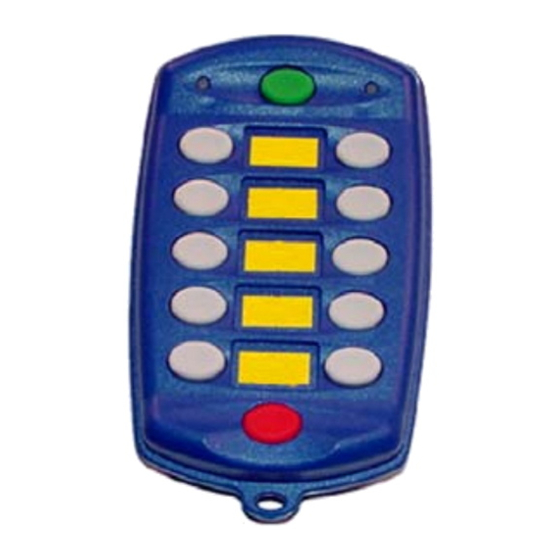
Power the Transmitter Install Batteries Remove the battery cover on the back of the transmitter using a slotted screwdriver and insert 4 "AA" alkaline batteries. Orientation of the batteries is embossed inside the battery housing. Turn on the Transmitter Refer to the Light Legend below for diagram details. T110 Battery Housing 1. -
Page 7: Download Id Code
Download ID Code (Use in case of Link Test failure) Follow these steps to download the transmitter’s unique ID Code into the receiver. This will allow the receiver to establish a radio link with that transmitter. Refer to the Light Legend below for diagram details. Refer to Troubleshooting Chart #4 for Tips and Considerations NOTE: It is necessary to download the ID Code when replacing either the transmitter or the receiver. - Page 8 Download ID Code (Use in case of Link Test failure) 4. Put R130 into Setup Mode ESTOP FAULT LINK STATUS ESTOP FAULT LINK STATUS A. Press & hold [Setup] button until (Status) light goes from slow flash to fast flash Setup Setup B.
-
Page 9: Changing Start Up And Shutdown Configuration
Changing Start Up and Shutdown Configuration The T110/R130 system has 3 available startup and shutdown modes that can be configured with the following steps. 1. Opening the R130 Case and Power the R130 ESTOP FAULT LINK STATUS A. The cap is held on by two plastic tabs at opposing sides, which can be unlatched as shown using a screwdriver. -
Page 10: Diagnostics-T110 Transmitter
Diagnostics—T110 Transmitter Indicator Lights Description Solution Occurs when ever a function is pressed. Will also remain on momentarily on Power To take it out of Download mode turn transmit- Transmitter is in Download mode. ter off and turn it back on again. Transmitter is in Operating mode. -
Page 11: Diagnostics-R130 Receiver
Diagnostics - R130 Receiver Normal Operation ESTOP FAULT LINK STATUS Transmitter is OFF If the transmitter is off, the receiver is operating properly. ESTOP FAULT LINK STATUS Transmitter is ON When the transmitter is turned on, the Link light (fast flashing) and E-Stop (GREEN) indicates the receiver is operating properly. -
Page 12: Troubleshooting Guide
Troubleshooting Guide Chart #1 Test the Receiver—R130 OK state: Status—GREEN Start Link—RED Initial Condition: What is the state E-Stop—RED Turn transmitter off (all lights are off—press the of the lights on Fault—OFF OFF button) the receiver? Cycle power to receiver (turn off and back on) Note: If there is a short to ground on an output, it is not indicated at this stage. - Page 13 Troubleshooting Guide (con’t) Chart #2 Test the Transmitter—T110 Turn off the receiver Ensure there are good batteries in the transmitter Turn on the transmitter The transmitter may be in secure mode (this will only be the case if the transmitter has been programmed for the secure mode feature) OK state: To check for this follow these steps:...
- Page 14 Troubleshooting Guide (con’t) Chart #3 Testing the Transmitter / Receiver Communication Transmitter: Transmitter: Active light is flashing Active light is flashing Receiver: Receiver: What is the status of Status—GREEN Status—GREEN the lights of both the Link—RED Link—Flashing GREEN transmitter and Fault—OFF Fault—OFF receiver?
- Page 15 Troubleshooting Guide Chart #4 Considerations when Downloading the ID Potential downloading issues If testing of the receiver and transmitter both show the system as working (Chart 1 & 2), then the transmitter and receiver will both go into Download/Configuration mode. Possible issues could arise during Step 4, the download phase of reprogramming.
-
Page 16: Parts & Accessories
OMNEX's entire liability and your exclusive remedy shall be, at interference received, including OMNEX's option, either the (a) repair or (b) replacement of the OMNEX product interference that may cause unde- which is returned within the warranty period to OMNEX freight collect by the Tel: 604-944-9247 sired operation.
Need help?
Do you have a question about the Origa T110 and is the answer not in the manual?
Questions and answers