Table of Contents
Advertisement
GENERIC
Installation / Configuration Manual
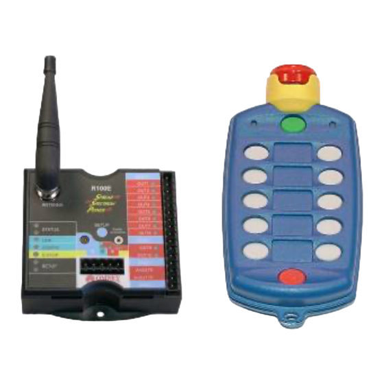
T110E Transmitter
R100 Receiver
Revised May 23, 2006
Version 3
DMAN - xxxx - xx
#74-1833 Coast Meridian Road, Port Coquitlam, BC, Canada • V3C 6G5
Ph# (604) 944-9247 • Fax# (604) 944-9267
Toll Free 1-800-663-8806
call toll free: 1-800-663-8806
www.omnexcontrols.com
DMAN-xxxx-xx (Rev x.x)
Advertisement
Table of Contents

Related Manuals for Omnex R100


Summary of Contents for Omnex R100
- Page 1 GENERIC Installation / Configuration Manual T110E Transmitter R100 Receiver Revised May 23, 2006 Version 3 DMAN - xxxx - xx #74-1833 Coast Meridian Road, Port Coquitlam, BC, Canada • V3C 6G5 Ph# (604) 944-9247 • Fax# (604) 944-9267 Toll Free 1-800-663-8806 call toll free: 1-800-663-8806 www.omnexcontrols.com...
-
Page 2: Table Of Contents
Power the Transmitter..........................6 Test the Transmitter / Receiver Link ......................6 Download ID Code ............................7 Configuring the System..........................8 Diagnostics—T110E Transmitter ......................... 11 Diagnostics—R100 Receiver ........................12 Troubleshooting Guide..........................13 Parts & Accessories ............................. 17 Specifications ............................... 17 Warranty Information............................ 17 NOTE: These instructions are intended only for installing and operating the remote control equipment described here. -
Page 3: System Overview
The eight function outputs may be configured for a variety of switching modes. The R100 Receiver also features a momentary ninth function and a “Link” output (output 10) that operates in one of five modes. The R100 Receiver is avail- able with either an internal or an external antenna. -
Page 4: Installing The Receiver
Use the Wiring Diagram and below to connect the receiver pins directly to the appropriate contacts of the machine electronics. R100 Output Cables are provided with every system to simplify the wiring process. Tips on mounting, power connections and filtering are also provided under Installation Considerations. -
Page 5: Special Functions
Mounting and Installation The R100 Receiver can be mounted by fastening two #8 screws with flat washers through the two mounting holes in the unit’s enclosure. When mounting, ensure that the R100 Receiver is oriented so that the text is reading right. -
Page 6: Power The Transmitter
Test the Transmitter / Receiver Link Follow these steps to ensure that there is a radio link between the transmitter and receiver. Refer to the Light Legend below for diagram details 1. Power the R100 2. Power the T110E STATUS... -
Page 7: Download Id Code
A. Press and Hold Power [OFF] B. Press and Hold Power [ON] C. Release Power [OFF] button D. Release Power [ON] button 3. Put R100 into Setup Mode SETUP SETUP A. Press & hold the BLUE [Setup] button until (Setup) -
Page 8: Configuring The System
Configuring the System NOTE: Every T110E / R100 system comes pre-configured and can be used without any additional changes. However, the configura- tion can be changed to suit a variety of specific applications. The configuration determines certain operating features of the system and the nature of the system functions. Changing the configuration therefore makes it possible to customize a function button to act as a Momentary, Latched or Maintained switch with an option of Interlocking paired functions. - Page 9 The Configuration Code is a 10-digit code that contains all the information necessary to customize the T110E / R100 system. Each of the 10 digits represents a specific function and there are a number of options, represented by a number or letter, available for each digit.
- Page 10 Retrieving the Configuration Code from the Receiver It is possible to check the Configuration Code that is stored in the R100 Receiver by following these steps. 1. Power the R100 in Configuration Check Mode OUT 1 OUT 1 OUT 2 OUT 2 A.
-
Page 11: Diagnostics-T110E Transmitter
Diagnostics—T110E Transmitter Indicator Lights Description Solution Occurs when ever a function is pressed. Will also remain on momentarily on Power To take it out of Download mode turn transmit- Transmitter is in Download mode. ter off and turn it back on again. Transmitter is in Operating mode. -
Page 12: Diagnostics-R100 Receiver
Diagnostics - R100 Receiver Normal Operation STATUS STATUS LINK LINK Transmitter is OFF Transmitter is ON CONFIG Output status is correct and the E-Stop relay is open CONFIG Transmitter and receiver have a radio link. and working properly. E-STOP E-STOP... -
Page 13: Troubleshooting Guide
Troubleshooting Guide Chart #1 Test the Receiver—R100 OK state: Status—GREEN Link—OFF Start Config—OFF Initial Condition: What is the state E-Stop—RED Turn transmitter off (all lights are off—press the of the lights on Setup—OFF Power OFF button) the receiver? Cycle power to receiver (turn off and back on) Note: If there is a wiring error in the out- puts, it is not indicated at this stage. - Page 14 Troubleshooting Guide (con’t) Chart #2 Test the Transmitter—T110E Turn off the receiver Ensure there are good batteries in the transmitter Turn on the transmitter The transmitter may be in secure mode (this will only be the case if the transmitter has been programmed for the secure mode feature) OK state: To check for this follow these steps:...
- Page 15 Troubleshooting Guide (con’t) Chart #3 Testing the Transmitter / Receiver Communication Transmitter: Transmitter: Active light is flashing Active light is flashing Receiver: What is the status of Receiver: Status—GREEN the lights of both the Status—GREEN Link—RED transmitter and Link—Flashing GREEN Fault—OFF receiver? Fault—OFF...
- Page 16 Troubleshooting Guide Chart #4 Considerations when Downloading the ID Potential downloading issues If testing of the receiver and transmitter both show the system as working (Chart 1 & 2), then the transmitter and receiver will both go into Download/Configuration mode. Possible issues could arise during Step 4, the download phase of reprogramming.
-
Page 17: Parts & Accessories
OMNEX's entire liability and your exclusive remedy shall be, at interference received, including OMNEX's option, either the (a) repair or (b) replacement of the OMNEX product interference that may cause unde- which is returned within the warranty period to OMNEX freight collect by the Tel: 604-944-9247 sired operation.
Need help?
Do you have a question about the R100 and is the answer not in the manual?
Questions and answers