
Subscribe to Our Youtube Channel
Related Manuals for BinTec X4000


Summary of Contents for BinTec X4000
- Page 1 X4000 User’s Guide Installation and Configuration © Copyright 2000 BinTec Communications AG, all rights reserved. Version 1.3 Document #71000L August 2000 X4000 User’s Guide...
- Page 2 The information in this manual is subject to change without notice. Additional information, including changes and release notes for X4000, can be found at www.bintec.de. As a multiprotocol router,...
- Page 3 German TÜV inspection/GS safety regulations BAKOM (Switzerland) registration had not been completed at the time this manual went to print. For further information on this, see the latest release notes at www.bintec.de. In addition to the CE directives, X4000 also meets the ISDN requirements in France and can be connected to Euro-Numeris.
- Page 4 X4000 User’s Guide...
-
Page 5: Table Of Contents
Advanced Configuration of the Basic Unit with the Setup Tool Configuration of Expansion and Resource Cards with the Setup Tool 277 Configuration of Security Functions and Firewall Configuration Management Troubleshooting Technical Data Important Commands General Safety Precautions in 15 Different Languages Glossary Index X4000 User’s Guide... - Page 6 Table of Contents X4000 User’s Guide...
-
Page 7: Table Of Contents
Table of Contents Welcome! X4000 – The Workgroup Access Router for Present and Future Applications Scope of Supply 1.2.1 Basic Unit 1.2.2 Expansion Cards BinTec Companion CD Documentation from BinTec System Requirements Guarantee Terms About this Manual 1.7.1 Contents 1.7.2 Meaning Feedback... - Page 8 Using the Input Keys 5.2.2 Meaning of LEDs 5.2.3 Navigation Bars Menu Architecture 5.3.1 Display Settings 5.3.2 IP Address and Netmask 5.3.3 Date and System Time 5.3.4 Information about X4000 Basic Unit 5.3.5 Information about X4000 Expansion Card X4000 User’s Guide...
- Page 9 Monitoring Useful Short-Cuts 5.4.1 Defining Default Screen 5.4.2 Saving the Configuration 5.4.3 Restarting X4000 Fast Configuration with the Configuration Wizard (Basic Unit) 109 In Advance of Configuration Installing BRICKware Basic X4000 Configuration with the Configuration Wizard Configuring a PC Testing your Configuration...
- Page 10 Compression 8.2.10 Proxy ARP (Address Resolution Protocol) 8.2.11 Keepalive Monitoring Basic IP Settings 8.3.1 System Time 8.3.2 Name Resolution in X4000 with DNS Proxy 8.3.3 Port Numbers 8.3.4 BOOTP Relay Agent IPX Settings 8.4.1 General Settings 8.4.2 Configuring the LAN Interface 8.4.3...
- Page 11 Configuration with the Setup Tool LAN Interface Card for 10/100 Mbps 9.3.1 Configuration with the Setup Tool 9.3.2 Broadband Internet Access (ADSL) with X4000 and LAN Expansion Card Resource Card with Digital Modems 9.4.1 X4000 with Digital Modems as Remote Access Server Resource Card for Encryption and Compression 9.5.1...
- Page 12 Administration of Configuration Files 11.2 Updating Software Troubleshooting 12.1 Aids to Troubleshooting 12.1.1 Man-Machine Interface (MMI) 12.1.2 Local SNMP Shell Commands 12.1.3 External Aids 12.2 Typical Errors and Procedure 12.2.1 System Errors 12.2.2 ISDN Connections 12.2.3 IPX Routing X4000 User’s Guide...
- Page 13 XTR-S/M/L – Resource Cards with Digital Modems 13.3.5 XTR-ENC – Resource Card for Encryption and Compression Important Commands 14.1 SNMP Shell Commands 14.2 BRICKtools for Unix Commands General Safety Precautions in 15 Different Languages Glossary Index Document #71000L, Version1.3 X4000 User’s Guide...
- Page 14 Table of Contents X4000 User’s Guide...
-
Page 15: Welcome
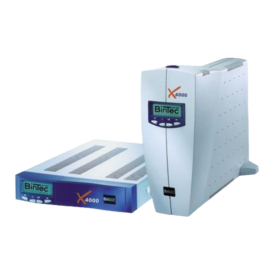
Welcome! Congratulations on deciding to buy the X4000 extendible multiprotocol router from the workgroup access series of BinTec Communications AG – an efficient and future-oriented router solution for use in small and medium-sized firms. Figure 1-1: X4000 - the workgroup access router for present and future applications... -
Page 16: X4000 - The Workgroup Access Router For Present And Future Applications
"Configuration Wizard" for fast basic configuration ensure ergonomic and user-friendly design. The newly developed Man-Machine Interface (MMI) from BinTec Communications AG with its LC display, input keys and intuitive user guide – in several languages – also simplifies "getting to know" your router and provides fast access and display of the main settings. - Page 17 We’ll keep working on it! You can download BinTec’s current software from the World Wide Web. You can find detailed information about the individual subjects in the relevant parts of this manual and in the more detailed documentation (on the BinTec Companion CD). X4000...
-
Page 18: Scope Of Supply
– Leaflet with X4000 guarantee information 1.2.2 Expansion Cards The following expansion cards can be purchased for X4000: X4E-1/2PRI: WAN interface card for ISDN PRI and/or G.703 – equipped as standard with hardware support for encryption and compression – to be optionally equipped with up to two resource cards with digital... - Page 19 (XTR-S, XTR-M) and/or – a resource card for encryption and compression (XTR-ENC) X4E-2FE: LAN interface card for 10/100 Mbps, to be optionally equipped with – a resource card for encryption and compression (XTR-ENC) X4000 User’s Guide...
-
Page 20: Bintec Companion Cd
BRICK at COM1 or BRICK at COM2. The Configuration Manager allows you to configure and administrate all BinTec routers in the network via a graphic interface. Here you can view and edit all SNMP tables and variables. The Java Status Monitor allows you to request system information over an Internet browser. - Page 21 BinTec Companion CD Please note: The license for RVS-COM Lite is a single user license. You can purchase additional licenses from your dealer. What else? The Companion CD also contains a range of other useful directories in which you can find the following, for example: The documentation in electronic form (see chapter 1.4, page...
-
Page 22: Documentation From Bintec
Welcome! Documentation from BinTec Together with X4000, you will have received part of the documentation in printed form and all of it in electronic form (PDF, HTML). The electronic versions of the different documents are included on the BinTec Companion CD. In addition to your Companion CD documentation, you can download all the very latest BinTec documentation from our WWW server at www.bintec.de. -
Page 23: System Requirements
System Requirements System Requirements X4000 can be configured from all conventional platforms. X4000 is a stand- alone device that is independent of the PC or operating system to which it is connected. The router communicates with the PC over a LAN interface (10/ 100 Mbps) or a serial connection. -
Page 24: Guarantee Terms
Please read the enclosed leaflet with detailed guarantee information for X4000. Danger! Live components are exposed when the equipment is open. There is a risk of... -
Page 25: About This Manual
Interface (MMI) – Display keys. with User Guide" 6: "Fast Configuration How to take X4000 into operation in a few with the Configuration minutes using the Windows tool Configuration Wizard (Basic Unit)" Wizard and how to install and set up other useful software. - Page 26 How to administrate configuration files and how Management" to perform software updates. 12: "Troubleshooting" Important tips on fault clearance. 13: "Technical Data" X4000 technical data. 14: "Important A brief overview of the most important Commands" commands of the SNMP shell and BRICKtools for Unix.
-
Page 27: Meaning
Caution (indicates possible danger that, if unheeded, could cause material damage) Warning (indicates possible danger that, if unheeded, could cause bodily harm) Danger (indicates danger that, if unheeded, could lead to serious bodily harm or death) Table 1-2: List of visual aids X4000 User’s Guide... - Page 28 Indicates fields in the Setup Tool and MIB bold, e.g. tables and variables. biboAdmLoginTable, Windows Start menu Indicates keys/key combinations Windows terms. italics, e.g. Indicates values that can be entered or set in the Setup Tool or MIB variables. none Table 1-3: Typographical elements X4000 User’s Guide...
-
Page 29: Feedback
X4000 and meets your requirements. You as the user of BinTec products are the best person to judge whether we have succeeded with this manual. So please let us know what is missing in this manual, what you don’t like, what we should do better, what you like, what you think is especially successful, etc. - Page 30 Welcome! X4000 User’s Guide...
-
Page 31: General Safety Precautions
Installation and Read the information on the ambient conditions (see Technical Data) operation before installing and operating X4000. Place the equipment on a firm flat base. Electrostatic charges may cause damage to the equipment. You should therefore wear a grounded wrist strap or touch a grounded surface before you touch sockets or extension cards of X4000. - Page 32 Make sure you follow the correct cabling sequence, as described in the manual. Use only the cables supplied with the equipment or cables that meet the specifications in this manual. If you use other cables, BinTec Communications AG cannot accept liability for any damage occurring or for any adverse effects on operation.
- Page 33 Unauthorized opening and improper repairs can result in serious danger for the user (e.g. electric shock). Ensure that repairs are only carried out by service centers authorized by BinTec. Your dealer will tell you where the service centers are situated. Failure to observe the above instructions invalidates the guarantee and no claims can be accepted.
- Page 34 General Safety Precautions X4000 User’s Guide...
-
Page 35: Hardware Description And Installation
Installation and replacement of expansion card, chapter 3.2.2, page 55 Setting up and connecting X4000, chapter 3.3, page 59 – "Connecting X4000 to PC or terminal", page 60 – "Connecting X4000 to LAN", page 60 – "Connecting X4000 to WAN", page 60 –... -
Page 36: Basic Unit
Hardware Description and Installation Basic Unit BinTec Communications AG offers you X4000 in two variants: Desktop unit for setting up in the office Built-in unit for 19-inch cabinet X4000 basic unit is not fitted with an expansion card in the ex works state. -
Page 37: Desktop Unit
Display and Input Keys BinTec’s Man-Machine Interface (MMI), a convenient user guide with display and input keys, guides the user through a number of basic functions of X4000. You will find a detailed description of the MMI in chapter 5, page X4000 User’s Guide... - Page 38 Display unit on The display unit on the 19-inch built-in unit can be mounted on the front or back 19-inch built-in unit of X4000. The instructions for changing the position are contained in "Step 2 Changing over the display", page X4000 User’s Guide...
- Page 39 Mini DIN socket (console) Fixing screws for expansion card and dummy cover Ethernet/LAN 10/100 Base-T Plastic strip for activating the Fast Ethernet interface buffer battery for the real-time clock (RTC) ISDN BRI interface Figure 3-2: Rear view of desktop unit X4000 User’s Guide...
-
Page 40: 19-Inch Built-In Unit
For connecting your desktop unit, go to chapter 3.3, page 3.1.2 19-Inch Built-In Unit Installing in a BinTec offers X4000 as a 19-inch built-in unit for installation in a 19-inch 19-inch cabinet cabinet. How to install your 19-inch unit in the 19-inch cabinet is described below. - Page 41 It is not necessary to open the housing for connecting or operating, or for installing or removing the expansion card. If the housing is opened, this tears the guarantee label on X4000, which invalidates the guarantee. Never open the housing! Danger! Live components are exposed when the equipment is open.
- Page 42 The following components and fixing parts are required for installation in a 19- inch cabinet: Mounting bracket Cover Fixing holes Power LED housing Display unit Figure 3-4: Exploded drawing showing the main components and mounting parts for the installation of X4000 in a 19-inch cabinet X4000 User’s Guide...
- Page 43 Screwing the bracket to the fixing holes Step 1 Using the two brackets and screws supplied with X4000, screw the brackets to the front fixing holes provided on the side of X4000, see Figure 3-5, page 43. Always use the screws supplied. Other screws may not withstand the mechanical loads or may damage the equipment.
- Page 44 Hardware Description and Installation This is what X4000 should look like on completion of installation. Figure 3-6: X4000 installed in a 19-inch cabinet For connecting your 19-inch built-in unit, go to chapter 3.3, page Removal from To remove X4000 from the 19-inch cabinet (e.g. for replacing or installing an 19-inch cabinet expansion card, installing a fan unit, etc.), carry out the steps described above...
- Page 45 It is not necessary to open the housing for connecting or operating, or for installing or removing the expansion card. If the housing is opened, this tears the guarantee label on X4000, which invalidates the guarantee. Never open the housing! Danger! Live components are exposed when the equipment is open.
- Page 46 Figure 3- 7, page This releases the plastic cover, which can be removed from the front. The blue Power LED with the BinTec logo is still visible after removing the front panel. Step 2 Changing over Disconnect the display cable from the RJ11 socket on the metal housing (Caution: The plug is locked to the socket;...
- Page 47 Figure 3-8: Removing the display Step 3 Turn the display unit by approx. 40 ° to the left and remove the display unit to the front away from the metal housing (bayonet connection), see Figure 3-8, page X4000 User’s Guide...
- Page 48 Hardware Description and Installation The following components and fixing parts are required for installation in a 19- inch cabinet with the X4000 connections to the front: Mounting bracket Bayonet connection for fixing the display unit Fixing holes Display cable Display unit...
- Page 49 Figure 3-10: Screwing the bracket to the fixing holes Step 4 Using the two brackets and screws supplied with the equipment, screw the brackets to the rear fixing holes provided on the side of X4000, see Figure 3-10, page 49. Always use the screws supplied. Other screws cannot withstand the mechanical loads or may damage the equipment.
- Page 50 Hardware Description and Installation Figure 3-11: Mounting the display on a fixing bracket Step 5 Mount the display unit on one of the two fixing brackets. Make sure that the display unit engages properly, see Figure 3-12, page X4000 User’s Guide...
- Page 51 Slide this preassembled unit with the two brackets screwed to it into the cabinet and screw the preassembled unit to the longitudinal sections of the cabinet (these screws are not supplied with X4000, but are included with the cabinet), see...
- Page 52 Hardware Description and Installation This is what X4000 should look like on completion of installation. Figure 3-13: X4000 installed with connections at the front For connecting your 19-inch built-in unit, go to chapter 3.3, page Removal from To remove X4000 from the 19-inch cabinet (e.g.
-
Page 53: Expansion And Resource Cards
You can extend your basic unit by adding an X4000 expansion card. The following expansion cards are offered by BinTec for integration in X4000: X4E-1/2PRI: WAN interface card for ISDN PRI and/or G.703 – equipped as standard with hardware support for encryption and compression –... - Page 54 ISDN BRI port LEDs Screws Figure 3-14: Rear view of a BRI expansion card PRI/G.703 Expansion Card X4E-1/2PRI ISDN PRI/G.703 port with IN LEDs and OUT socket Screws Figure 3-15: Rear view of a PRI/G.703 expansion card X4000 User’s Guide...
-
Page 55: Installation And Replacement Of Expansion Card
Figure 3-16: Rear view of a LAN expansion card 3.2.2 Installation and Replacement of Expansion Card Now you can find out how to equip the X4000 basic unit with an expansion card or replace this with one of the other X4000 expansion cards. Make sure you also follow the installation guide supplied with the expansion and resource cards. - Page 56 Do not touch any parts inside the expansion slot when installing or replacing the expansion card. There is a risk of electric shock! Do not touch any parts inside the expansion slot of X4000! Caution! Electrostatic charges can damage electronic components. Please observe the...
- Page 57 Mount the resource card(s) on the expansion card, if applicable. Follow the installation guide supplied with the resource card. Push the expansion card into the slot provided in the housing until it engages in the slot connector. Card guides ensure that the expansion card X4000 User’s Guide...
- Page 58 If you are using an expansion card with resource card(s) in the X4000 built-in unit, BinTec Communications AG recommends that you use the fan unit obtainable as optional equipment. Removal To remove an expansion card, carry out the installation steps described above in the reverse order.
-
Page 59: Setting Up And Connecting
Mini DIN socket (console) Fixing screws for expansion card and dummy cover Ethernet/LAN 10/100 Base-T Plastic strip for activating the Fast Ethernet interface buffer battery for the real-time clock (RTC) ISDN BRI interface Figure 3-18: X4000 rear view X4000 User’s Guide... - Page 60 Connecting X4000 Connect the serial port of your PC (COM1 or COM2) to the console interface of your X4000. Use only the serial cable supplied with the PC or equipment. terminal You only need to connect X4000 to the console interface (no.
- Page 61 Setting Up and Connecting We recommend you use original BinTec cables, which you can buy from your dealer. The use of other cables may cause damage to your equipment and invalidates the guarantee! Real-time clock Finally, you must activate the buffer battery of the real-time clock:...
- Page 62 Hardware Description and Installation and the red LED on the back of X4000 go out at the end of the selftest. The blue Power LED lights as long as X4000 is supplied with power. The status messages displayed by (LEDs) are described in chapter 3.4,...
-
Page 63: Status Messages Via Leds
LEDs on the expansion cards are given below. 3.4.1 Basic Unit Power LED The blue Power LED inside the BinTec logo on the front of X4000 (see Figure 3- 1, page 37) lights as soon as X4000 is supplied with power. -
Page 64: Expansion Cards
Table 3-2: LED status messages of a BRI expansion card PRI/G.703 Expansion Card X4E-1/2PRI The PRI/G.703 expansion card has two LEDs. The top LED is assigned to the first port (Unit 0) and the bottom LED to the second port (Unit 1). X4000 User’s Guide... - Page 65 – 100 Mbps Mode (Fast Ethernet) – 10 Mbps Mode (Ethernet) – – Port is not available – Ethernet collision – – No Ethernet collision Table 3-4: Status messages of LEDs on a LAN expansion card X4000 User’s Guide...
-
Page 66: Boot Sequence
All configuration files are deleted and the BOOTmonitor settings are set to the default values. (5) Default BOOTmonitor parameters: You can change the default settings of X4000’s BOOTmonitor, e.g. the baud rate for serial connections. X4000... - Page 67 If you change the baud rate (the preset value is 9600 baud), make sure the terminal program used also uses this baud rate. If this is not the case, you will not be able to establish a serial connection to X4000! X4000...
- Page 68 Hardware Description and Installation X4000 User’s Guide...
-
Page 69: Configuration Requirements
Configuration Requirements This chapter tells you how to carry out the following tasks: How to access X4000 (chapter 4.1, page How to log in to X4000 (chapter 4.2, page Which methods of configuration are available to you (chapter 4.3, page... -
Page 70: Connection Methods
Configuration Requirements Connection Methods Before you can configure your X4000, you must connect X4000. There are various ways of doing this: Over the Man-Machine Interface (MMI) Over the serial interface Over your Over an ISDN connection Serial Connection 4000 isdnlogin... -
Page 71: Man-Machine Interface (Mmi)
Man-Machine Interface (MMI) Initial steps The MMI with its display and input keys is a good method for establishing “initial contact” with X4000. You should carry out the following initial steps with the MMI: set the desired display language enter the IP address and netmask You can then carry out further configuration steps using the Configuration Wizard or Setup Tool. - Page 72 Configuration Requirements If the login prompt does not appear after pressing Return several times, the connection to X4000 has not been set up successfully. Check the COM1 or COM2 settings on your PC. Click File Properties. Click Configure..in the Connect to tab.
-
Page 73: Connecting Over A Lan
X4000 in the window under BRICK Parameter. Click OK. Close DIME Tools. Running telnet Now establish a connection to X4000 with telnet: Windows Click the Windows Start button and then Run..Type telnet <IP address of X4000>. X4000 User’s Guide... -
Page 74: Connection Over Isdn
Connection is then obtained by means of a BinTec router that is already configured or an ISDN card in the remote LAN, using a number of X4000’s ISDN connection in your own LAN (e.g. 1234). - Page 75 ISDN. To reach X4000 over ISDN login, proceed as follows: Log in on your BinTec router in the remote LAN in the usual way. In the SNMP shell, type in isdnlogin <number ISDN connection of X4000>, e.g. isdnlogin 1234.
-
Page 76: Logging In
Configuration Requirements Logging In Regardless of how you access X4000, the SNMP shell X4000 with the login prompt always appears first. Exceptions to this rule are the Configuration Wizard and Configuration Manager under Windows and the MMI. In order to log in, you need to know the user name and password. In its ex works... - Page 77 Logging In Type in your password (e.g. bintec) and press Return. Your router then issues an input prompt, e.g. X4000:>. The login was successful. Caution! To prevent unauthorized access to X4000, you should change the passwords right away. How to change the passwords is described in "Changing the...
-
Page 78: Configuration Options
Setup Tool. This manual explains how to configure X4000 by means of the Setup Tool. 4.3.1 Methods of Configuration Methods of configuring X4000: Man-Machine Interface (MMI) Configuration Wizard Setup Tool SNMP shell commands... -
Page 79: Using The Setup Tool
BinTec Communications AG. You can use its interface based on Windows other SNMP managers Explorer to access all MIB tables and variables of X4000. You can also use other SNMP managers, such as SNM, HP Open View or Transview, to access and modify the MIB tables and variables. - Page 80 Setup Tool menu system. The system name of X4000 is also displayed. This is especially helpful if you are using several BinTec routers with different system names. The configuration window is where the actual entries are made and the respective settings displayed.
- Page 81 Configuration Options The help line tells you how to move around in the menu currently displayed or which entries you can change. X4000 User’s Guide...
- Page 82 To scroll back a page in a long list. An "=" sign at the top right indicates the start of the list or a "∧" indicates more to come. Ctrl - c Leave the Setup Tool. Table 4-2: Navigation in the Setup Tool X4000 User’s Guide...
- Page 83 Any entries made are lost. Table 4-3: Buttons in the Setup Tool Searching lists Some Setup Tool menus contain lists of items, e.g. the WAN P menu, ARTNER which lists all WAN partners currently configured. X4000 User’s Guide...
- Page 84 Configuration Requirements X4000 Setup Tool BinTec Communications AG [WAN]: WAN Partners MyRouter Current WAN Partner Configuration Partnername Protocol State ∧ BigBoss dormant T_ONLINE dormant Partner1 dormant Partner2 dormant PROVIDER dormant DELETE EXIT Press<Ctrl-n>,<Ctrl-p>toscroll,<Space>tag/untag DELETE,<Return>to edit Search: p These lists are in alphabetical order according to the contents of the first field.
- Page 85 Search results Changing the The procedure described below for changing the password applies to all X4000 password passwords: the access passwords for the user names admin, read and write, the HTTP password, the RADIUS password, the PPP password, the provider password and the CAPI user passwords.
- Page 86 If the two passwords you entered were not the same, the field is reset to the old password and Password doesn’t match Try again. is displayed in the help line. Menu structure The main menu of the Setup Tool looks like this: X4000 Setup Tool BinTec Communications AG MyRouter Licenses System...
- Page 87 Configuration Options The menu structure of the Setup Tool looks like this: LAN: WAN: Serial-WAN: Figure 4-4: Setup Tool menu structure (basic unit) X4000 User’s Guide...
- Page 88 This menu is for entering the license information printed on the license card ICENSES supplied with the equipment. This menu is also used for activating extra licenses. In this menu, you enter the basic system settings of X4000, e.g. system YSTEM name and passwords. THERNET This menu is for configuring the interface of X4000.
- Page 89 SNMP is for changing the basic SNMP settings. RADIUS S is for configuring RADIUS servers. ERVER DNS is for defining the procedure for name resolution in X4000. is for controlling access to the OCAL ERVICES CCESS ONTROL local UDP and TCP services in X4000.
- Page 90 Includes the settings for BinTec's CAPI user concept. You can use this to assign user names and passwords to users of the X4000's CAPI applications. This makes sure that only authorized users can receive incoming calls and make outgoing calls via CAPI.
-
Page 91: Procedure For Initial Configuration
Procedure for Initial Configuration Procedure for Initial Configuration We recommend the following procedure for initial configuration of X4000: Carry out the first configuration steps using the MMI (see chapter 5, page 93). X4000 should not yet be connected to the LAN for this work, only the power cord must be connected: –... - Page 92 Configuration Requirements X4000 User’s Guide...
-
Page 93: Man-Machine Interface (Mmi) - Display With User Guide
Man-Machine Interface (MMI) – Display with User Guide BinTec’s Man-Machine Interface (MMI) with display and input keys simplifies "getting to know" your X4000 and provides easy access to status information. BINTEC X4000 Figure 5-1: MMI with display and input keys (logo) -
Page 94: Overview
Overview Getting started You can use the MMI to enter X4000’s IP address and netmask without first having to set up a serial connection to X4000. This simplifies the initial configuration, as you can first assign an IP address to... - Page 95 Overview You can change from Monitoring Mode to Configuration Mode and vice versa in the main menu "Display Settings", see chapter 5.3.1, page 100. X4000 User’s Guide...
-
Page 96: Display And Input Keys
To select a menu item, press OK. You then change to the next lower level, in which you can also navigate by means of In the menu You can execute the following actions in a menu: Select a value (e.g. display brightness) with and then confirm with OK. X4000 User’s Guide... -
Page 97: Meaning Of Leds
Enter numbers (e.g. IP address or PIN) with and then confirm with OK. Display a value (e.g. serial number of X4000) and then leave the menu with Leaving the menu with To leave a menu and change to the next higher menu level without changing a setting, just press C. -
Page 98: Navigation Bars
The horizontal navigation bar at the bottom edge indicates in which menu of the second level of the corresponding main menu you are located. The following figures of the menu architecture also show the associated navigation bars. X4000 User’s Guide... -
Page 99: Menu Architecture
IP Address and Netmask (see chapter 5.3.2, page 102) Date and System Time (see chapter 5.3.3, page 103) Information about X4000 Basic Unit (see chapter 5.3.4, page 104) Information about X4000 Expansion Card (see chapter 5.3.5, page 105) Monitoring (see chapter 5.3.6, page... -
Page 100: Display Settings
Enter current PIN: ..l 0000 Enter new PIN: 1234 Retype new PIN: 1234 PIN has been IP Address and changed Netmask Figure 5-5: Menus for selecting the display settings (with navigation bars) X4000 User’s Guide... - Page 101 For technical reasons, the PIN is shown on the display in plain language. Make sure the display is not visible to other persons when you enter the PIN. Users who do not know the set PIN cannot change from Monitoring Mode to Configuration Mode. X4000 User’s Guide...
-
Page 102: Ip Address And Netmask
Menus for entering the IP address and netmask (with navigation bars) IP Address Enter the IP address of X4000. This is done by selecting each digit with and confirming each by pressing OK. The IP address is saved after confirming the last digit. -
Page 103: Date And System Time
Figure 5-7: Menus for entering date and system time (with navigation bars) System Date For setting the current date in X4000. This is done by selecting the day, month and year in succession with and confirming each by pressing OK. -
Page 104: Information About X4000 Basic Unit
Man-Machine Interface (MMI) – Display with User Guide 5.3.4 Information about X4000 Basic Unit The main menu "Information about X4000 Basic Unit" offers the following options for displaying system information: Limit: ... Information Credits Based Last: ... about X4000 Accounting System Total: ... -
Page 105: Information About X4000 Expansion Card
Logic Version Displays the version of X4000’s firmware logic. Hardware Revision Displays the hardware version of X4000. Software Release Displays the system software version used by X4000. Onboard Interfaces Displays the status of the X4000 hardware interfaces available with the basic unit. -
Page 106: Monitoring
Man-Machine Interface (MMI) – Display with User Guide 5.3.6 Monitoring The main menu "Monitoring" offers a facility for monitoring the operating temperature of X4000: °C 40 50 60 Current temperature Monitoring Temp Temp1 Temp2 Figure 5-9: Menus for monitoring X4000... -
Page 107: Useful Short-Cuts
Confirm with OK. The selected screen is shown and used as default screen. 5.4.2 Saving the Configuration Proceed as follows to save the current configuration of X4000 using the input keys. Keep the OK key pressed for three seconds. Do you want... -
Page 108: Restarting X4000
Keep the OK key and C key pressed for three seconds. ATTENTION! Do you really want to reboot X4000? Press OK. System reboot in 5 seconds! The restart is executed after 5 seconds. System reboot ... Standby until X4000 is up again! X4000 User’s Guide... -
Page 109: Fast Configuration With The Configuration Wizard (Basic Unit)
With the Configuration Wizard on your BinTec Companion CD, BinTec Communications AG offers you a quick and convenient way to start running your X4000. You can perform basic configuration via the serial connection of your Windows PC. This basic configuration includes all the important settings of the router, access to the Internet via an Internet Service Provider (ISP), as well as connection to a WAN partner (e.g. -
Page 110: In Advance Of Configuration
In Advance of Configuration Router settings Before you start to configure your X4000, make sure you know the following information about your ISDN connection and your network environment. Write down your values in the table below so that you can quickly find the necessary information while you are performing the configuration. - Page 111 "partner’s name" and your partner’s entry for "local name" must also be identical. TCP/IP protocol Make sure the TCP/IP protocol is installed on the PC before you start the configuration. testing and installation X4000 User’s Guide...
-
Page 112: Installing Brickware
The DIME Tools, which are part of BRICKware for Windows, contain mainly assistants for configuration, administration and diagnosis of your X4000. For the basic operation of X4000, it is not necessary to have DIME Tools started automatically by Windows. Start the Configuration Wizard at the end of the installation. -
Page 113: Basic X4000 Configuration With The Configuration Wizard
Basic X4000 Configuration with the Configuration Wizard Basic X4000 Configuration with the Configuration Wizard Configuration of the basic settings of X4000 is quick and easy with the Configuration Wizard. Please note: If you have already created a configuration with the Configuration Wizard, the Wizard may assume the preset values. At the end, the configuration is transferred to the router and saved on the PC. - Page 114 (CAPI). Select the desired items and follow the instructions on the screen. Caution! All BinTec routers are shipped with the same user names and passwords. As long as the password remains unchanged, they are not protected against unauthorized use.
-
Page 115: Configuring A Pc
An online help system is also available. installation Internet access with You can set up WAN access over X4000, e.g. to the Internet, for all PCs located X4000 in a network with X4000. In order to do this, you must enter... - Page 116 Fast Configuration with the Configuration Wizard (Basic Unit) Click the DNS Configuration tab and enter the IP address of X4000 under DNS Server Search Order. Click Add and then OK. Follow the instructions on the screen. X4000 User’s Guide...
-
Page 117: Testing Your Configuration
93) or check your settings with an SNMP Management Tool. LAN connection Test the connection to your X4000. In the start menu of your PC, click Run and enter ping, followed by a space and the IP address of X4000, e.g. testing ping 192.168.1.254. - Page 118 Fast Configuration with the Configuration Wizard (Basic Unit) X4000 User’s Guide...
-
Page 119: Basic Configuration Of Basic Unit With Setup Tool
This chapter describes the steps you must always carry out for taking X4000 into operation, irrespective of the environment or applications for which you use X4000. You can also carry out the steps described here using the Configuration Wizard (see chapter 6, page 109). -
Page 120: Basic Router Settings
Basic Configuration of Basic Unit with Setup Tool Basic Router Settings The configuration of the basic router settings concerns only your X4000 your local network. 4000 Your Local Area Network Figure 7-1: Basic router settings – X4000 in the LAN... -
Page 121: Entering License(S)
DELETE EXIT Press<Ctrl-n>,<Ctrl-p>to scroll,<Space>tag/untagDELETE,<Return>to edit Listed under Available Licenses are all subsystems available to X4000, as well as their current state ( builtin - always available, valid - activated, not_valid - not activated). The license entries are shown under (Serialnumber, Mask, Key). - Page 122 Basic Configuration of Basic Unit with Setup Tool Subsystems The following subsystems can be activated on your X4000: Subsystems Meaning IP routing OSPF Open Shortest Path First (only with extra license) Token Authentication Firewall (only with extra license) TUNNEL Virtual Private Networking VPN (only with extra...
-
Page 123: Entering System Data
If not ok is shown as the state, you have probably made a typing error. Try again. 7.1.2 Entering System Data System name, ... Now you should enter the basic system data for your X4000. Go to S YSTEM X4000 Setup Tool BinTec Communications AG... - Page 124 System Name Defines the system name of X4000, is also used as PPP host name. Appears as input prompt when logging in to X4000. If no system name is set, a warning appears on logging in with the user name admin.
- Page 125 Basic Router Settings Caution! All BinTec routers are shipped with the same user names and passwords. As long as the password remains unchanged, they are not protected against unauthorized use. How to change the passwords is described in "Changing the password", page...
-
Page 126: Configuring The Lan Interface
242). 7.1.3 Configuring the LAN Interface address, Now configure the LAN interface (10/100 Base-T Ethernet) of X4000. The LAN netmask, interface is the physical interface to the local network. In the following menu, Encapsulation enter the address where your router can be reached in the LAN. As long as your router does not have this entry, it cannot be recognized by other hosts in the network. - Page 127 MMI before the basic configuration. Even if you have, you should still check the entries in the following menu. Go to CM-100BT, F THERNET X4000 Setup Tool BinTec Communications AG [LAN]: Configure LAN Interface MyRouter IP Configuration Local IP Number 192.168.1.254...
- Page 128 Basic Configuration of Basic Unit with Setup Tool The following parts of the menu are relevant for this configuration step: Field Meaning Local IP Number IP address of X4000 in the LAN. Local Netmask Netmask of the network in which X4000 with Local IP Number is located.
-
Page 129: Configuring X4000 As Dhcp Server
PCs in the LAN. A PC sends out an ARP request and in turn receives its IP address assigned by X4000. You do not need to assign fixed IP addresses to PCs, which reduces the amount of configuration work in your network. - Page 130 DNS), NetBIOS name server (WINS) and standard gateway. Go to IP LAN (DHCP) ADD: ADDRESS POOL X4000 Setup Tool BinTec Communications AG [IP][DHCP][ADD]: Add Range of IP Addresses MyRouter Interface IP Address 192.168.1.1 Number of Consecutive Addresses Lease Time (Minutes)
- Page 131 MAC Address. Gateway Defines which IP address is assigned to the DHCP client as gateway. If no IP address is entered here, the IP address of X4000 is also given. NetBT Node Type Defines how and in what order the assignment of NetBIOS names to IP addresses is attempted for the hosts of an address pool.
-
Page 132: Setting Filters
This prevents establishing connections from the network to your Internet Service Provider ( ISP), e.g. in order to forward WINS requests from PCs in your network. This means that X4000 asks your ISP which host name can be assigned an IP address. - Page 133 Basic Router Settings Go to IP ADD: CCESS ISTS ILTER X4000 Setup Tool BinTec Communications AG [IP][ACCESS][FILTER][ADD]: Configure IP Access Filter MyRouter Description wrong_dns Index Protocol Source Address Source Mask Source Port specify Specify Port Destination Address Destination Mask Destination Port...
- Page 134 To define rules for these filters, proceed as follows: Go to IP ADD: CCESS ISTS ULES X4000 Setup Tool BinTec Communications AG [IP][ACCESS][RULE][ADD]: Configure IP Access Rules MyRouter Action deny M Filter...
- Page 135 Basic Router Settings X4000 Setup Tool BinTec Communications AG [IP][ACCESS][RULE]: Configure IP Access Rules MyRouter Abbreviations: RI (Rule Index) M (Action if filter matches) FI (Filter Index)!M (Action if filter does not match) NRI (Next Rule Index) Action Filter Conditions...
-
Page 136: Where Do We Go From Here
The configuration of the basic router settings is complete. 7.1.6 Where do we go from here? After you have configured X4000 for your LAN, you can carry out the following steps to permit WAN connections. Configure the WAN interface(s) of... -
Page 137: Configuring Wan Interfaces
155). If you use a LAN expansion card, see chapter 9.3.2, page 288. Installing an expansion card enables other WAN interfaces to be used on X4000, if applicable (see chapter 9, page 277). 7.2.1 Configuring the ISDN BRI Interface You can use the ISDN BRI interface of... - Page 138 Basic Configuration of Basic Unit with Setup Tool X4000 Setup Tool BinTec Communications AG [WAN]: WAN Interface MyRouter Result of Autoconfiguration: Euro ISDN, point-to-multipoint ISDN Switch Type autodetect on bootup D-Channel dialup B-Channel 1 dialup B-Channel 2 dialup Incoming Call Answering>...
- Page 139 B1+B2 channel (64S2): leased line over both B-channels leased line D+B1+B2 channel (TS02): leased line over D-channel and both B- channels leased line B1+B2 different endpoints (digital 64S with dual connection): leased line to two different endpoints X4000 User’s Guide...
- Page 140 Make the following entries: Select ISDN Switch Type: autodetect on bootup . This setting enables X4000 to use its automatic D-channel detection. As long as the D-channel detection is running, running appears next to Result of Autoconfiguration. Once the setting has been found, it is displayed, e.g.
- Page 141 X4000 supports the following services: PPP (Routing): service is X4000’s general routing service. This connects incoming data calls from WAN partners’ dialup connections to your LAN. This enables partners outside your own local network to access hosts within your LAN. This subsystem also enables outgoing data calls to be set up to WAN partners outside your local network.
- Page 142 Called Party Number (CPN) and the type of call (data or voice call). The CPN is the extension the partner has dialed to reach X4000. Then the call is forwarded to the corresponding service (see Figure 7-3, page 142).
- Page 143 CAPI subsystem. All calls to the CAPI are offered to all CAPI applications in the LAN. To distribute incoming calls for the CAPI subsystem to defined users with password, you should use BinTec’s User Concept (see chapter 8.1.2, page 190).
- Page 144 Basic Configuration of Basic Unit with Setup Tool X4000 Setup Tool BinTec Communications AG [WAN][INCOMING]: Incoming Call Answering MyRouter Item Number Mode Username CAPI 1.1 EAZ 1 Mapping right to left CAPI 1.1 EAZ 1 Mapping right to left ISDN Login...
- Page 145 Number Phone number under which the service (Item) entered above can be reached. Mode Mode in which X4000 compares the digits of Number with the called party number of the incoming call: right to left (default value) left to right (DDI): Always select if X4000 connected to a point-to-point connection.
- Page 146 Enables PPP connections with V.110 at bit (1200...38400) rates of 1200 bps, 2400 bps,..., 38400 bps. Pots Not available in X4000. PPP Modem Profile 1...8 (Only available if expansion card and resource card with digital modems are installed) Assigns incoming analog calls to the PPP routing service.
- Page 147 X4000! For example, if X4000 is connected to a PABX, only the PABX extension number arrives at X4000. If you are not sure which number arrives at X4000, proceed as follows: Call X4000 with a conventional telephone using one of its extension numbers.
-
Page 148: Configuring Serial Interfaces
Repeat these steps until you have assigned to all phone numbers the services to be reached under these numbers. This concludes the configuration of Incoming Call Answering. X4000 distributes the incoming calls to the internal services. Advanced CM-1BRI, ISDN S0 contains settings for X.31 TEI (see... - Page 149 The setting in the Setup Tool Connector field (see Table 7-11, page 153) enables the port to be changed so that X4000 can be operated in both DCE and DTE Mode. Making the relevant settings in the Setup Tool Connector field physically reverses the signal direction and the pin functions.
-
Page 150: Configuration With The Setup Tool
Basic Configuration of Basic Unit with Setup Tool Configuration with the Setup Tool The following menu is available for configuring the X.21/V.35/V.36 and X.21bis interface of X4000: X4000 Setup Tool BinTec Communications AG [SLOT 3 UNIT 0 SERIAL]:Configure Serial Interface... - Page 151 ERIAL Possible values: dte (default value): The pins are assigned as DTE interface. This setting is necessary, for example, if X4000 is connected to a public data network (e.g. Datex-P in Germany). dce : The pins are assigned as DCE interface.
- Page 152 Defines which connection partner sends the clock signal for synchronization between transmitter and receiver. Possible values: auto (default value): The setting is based on the Connector selected: – X4000 sends the clock signal if Connector = dce . – X4000 receives the clock signal if Connector = dte .
- Page 153 DTE. dce: The address field has the value for DCE. Interface Leads Defines whether X4000 checks the status of the interface lines. The same value should be set for both connection partners. Possible values: enabled: The status of the signal line (I for X.21, CTS for V.35, V.36 and X.21bis) is...
- Page 154 Table 7-12: Use of Connector in the Setup Tool To do Proceed as follows to configure the serial interfaces (the example values given are necessary if you connect X4000 to Datex-P): Go to CM-SERIAL, S 0 or CM-SERIAL, S ERIAL ERIAL Select Interface Type: e.g.
-
Page 155: Configuring The Lan Interface For Using Adsl (Ppp-Over-Ethernet)
7.2.3 Configuring the LAN Interface for Using ADSL (PPP-over-Ethernet) ADSL To be able to use ADSL (Asymmetric Digital Subscriber Line) with X4000, you must configure a PPP-over-Ethernet interface over the LAN interface. This is done by connecting X4000 to T-DSL, which is the ADSL connection of Deutsche Telekom AG. - Page 156 Basic Configuration of Basic Unit with Setup Tool The T-DSL connection (without X4000) looks like this: Customer 768 kbit/s T-ISDN ADSL T-ISDN dsl 128 kbit/s ISDN telephone ISDN-NTBA ADSL Splitter (BBAE) PC with network card ADSL modem (NTBBA) Figure 7-4:...
- Page 157 Configuring WAN Interfaces Your Local Area Network Figure 7-5: Example scenario (with X4000) The following settings are necessary (the Setup Tool menus concerned are described elsewhere): Go to PPP (see chapter 8.1.3, page 194). Select PPPoE Ethernet Interface: en1 .
- Page 158 Enter Metric: e.g. 1 . Press SAVE. Go to IP (see "Activating Network ETWORK DDRESS RANSLATION Address Translation (NAT)", page 181). Select the PPPoE interface, e.g. t-online, and confirm with Return. Select Network Address Translation: on. Press SAVE. X4000 User’s Guide...
-
Page 159: Configuring Wan Partners
If you have set up one or more leased lines on configuring the WAN interface(s) of X4000, a WAN partner for each leased line is already created automatically in the WAN Partner menu. Edit this entry to suit your requirements. - Page 160 110). The terms used may vary slightly from provider to provider. To enter a WAN partner, proceed as follows: Go to WAN P ARTNER X4000 Setup Tool BinTec Communications AG [WAN]: WAN Partners MyRouter Current WAN Partner Configuration Partnername...
- Page 161 To make an entry in the list, proceed as follows: Use ADD to add a new entry or select an existing entry. Confirm with Return to change the entry. Another menu window opens: X4000 Setup Tool BinTec Communications AG [WAN][ADD]: Configure WAN Partner MyRouter...
- Page 162 Multi-Protocol HDLC Framing Async PPP over X.75 Async PPP over X.75/T.70/BTX X.25_PPP X.25 HDLC Framing (IP only) LAPB Framing (IP only) X31 B-Channel X.25 No Signaling X.25 PAD X.25 No Configuration Frame Relay X.25 No Configuration, No Signaling X4000 User’s Guide...
- Page 163 ( CLID). The value of this field is dependent on Direction in the submenu WAN N and cannot be set here. UMBERS WAN P Table 7-13: ARTNER X4000 User’s Guide...
- Page 164 Select Compression, e.g. none , if applicable. Select Encryption, e.g. none , if applicable. Go to WAN P WAN N ARTNER UMBERS Entering extension numbers X4000 Setup Tool BinTec Communications AG [WAN][ADD][WAN Numbers]: WAN Numbers (BigBoss) MyRouter WAN Numbers for this partner: WAN Number Direction 0911987654321...
- Page 165 Possible values Meaning outgoing For outgoing calls, where you dial your WAN partner. both (CLID) For incoming and outgoing calls. incoming (CLID) For incoming calls, where your WAN partner dials in to your X4000. Table 7-16: Direction X4000 User’s Guide...
- Page 166 Basic Configuration of Basic Unit with Setup Tool When X4000 is connected to a PABX system for which a "0" prefix is necessary for external line access, this "0" must be considered when entering the access number. Wildcards When entering the Number, you can either enter the extension digit for digit or you can replace single numbers or groups of numbers with wildcards.
- Page 167 When a call is received, the Calling Party Number is always sent over the ISDN D-channel. This number enables X4000 to identify the caller CLID), provided the caller is entered as a WAN partner. After identification with CLID, the router can additionally carry out PPP authentication with the WAN partner before it accepts the call.
- Page 168 Basic Configuration of Basic Unit with Setup Tool X4000 Setup Tool BinTec Communications AG [WAN][ADD][PPP]: PPP Settings (BigBoss) MyRouter Authentication CHAP + PAP Partner PPP ID LittleIndian Local PPP ID BigBoss PPP Password Secret Keepalives Link Quality Monitoring CANCEL Use <Space> to select...
- Page 169 Enter Local PPP ID, e.g. BigBoss . How to enter the passwords is described in "Changing the password", page Enter PPP Password, e.g. Secret . Select Keepalives, e.g. off . Select Link Quality Monitoring, e.g. off . X4000 User’s Guide...
- Page 170 In some cases, the caller cannot be identified with CLID, although entered as a WAN partner. In this case, your X4000 does not know which authentication protocol was set for this WAN partner. To enable the call to still be accepted,...
- Page 171 AOCD fails. You should make sure static Short Hold comes into operation later than dynamic Short Hold. If not, X4000 always clears the connection based on static short hold and never gives dynamic short hold a chance to disconnect. In this case, enter a value for Static Short Hold (sec) that is a little more than the expected maximum dynamic idle time.
- Page 172 Basic Configuration of Basic Unit with Setup Tool X4000 Setup Tool BinTec Communications AG [WAN][ADD][ADVANCED]: Advanced Settings (BigBoss) MyRouter Callback Static Short Hold (sec) Idle for Dynamic Short Hold (%) Delay after Connection Failure (sec) 300 Layer 1 Protocol ISDN 64 kbps Channel Bundling Extended Interface Settings (optional) >...
- Page 173 IP address netmask of your partner. Proceed as follows: Go to WAN P IP : ARTNER X4000 Setup Tool BinTec Communications AG [WAN][ADD][IP]: IP Configuration (BigBoss) MyRouter IP Transit Network Partner’s LAN IP Address 10.1.1.0 Partner’s LAN Netmask 255.255.255.0 Advanced Settings >...
- Page 174 WAN partner. Local IP Address IP address of X4000. You do not normally need to make an entry here, unless you wish to configure a transit network for one of your WAN partners (see chapter 8.2.6, page...
- Page 175 This setting is only necessary if you have not entered fixed IP addresses for DNS on the PCs of your network. Creating a Routing Entry Routing entry You have just entered a WAN partner in your X4000. A routing entry is created creation automatically in the routing table of your X4000 for every WAN partner.
- Page 176 Basic Configuration of Basic Unit with Setup Tool X4000 Setup Tool BinTec Communications AG [IP][ROUTING]: IP Routing MyRouter The flags are: U (Up), D (Dormant), B (Blocked), G (Gateway Route), I (Interface Route), S (Subnet Route), H (Host Route), E (Extended Route)
- Page 177 Configuring WAN Partners X4000 Setup Tool BinTec Communications AG [IP][ROUTING][ADD]: IP Routing MyRouter Route Type Network route Network WAN without transit network Destination IP Address 10.1.1.0 Netmask 255.255.255.0 Partner / Interface BigBoss Metric SAVE CANCEL Use <Space> to select X4000...
- Page 178 Partner / Interface WAN partner (only possible for Network = WAN without transit network ). Gateway IP Address IP address of the host to which X4000 should forward the IP packets. Metric The lower the value, the higher the priority of the route (range of values 1...14).
- Page 179 Table 7-23: Network You can only configure one default route on your X4000. If you set up access to the Internet, you must therefore configure the route to your Internet Service Provider (ISP) as a default route.
- Page 180 Subnet 1 of your Company’s Head Office Figure 7-7: Network with subnets Network route To establish a network route, e.g. for a corporate network connection (without a default route), proceed as follows: Select Route Type: Network route . X4000 User’s Guide...
- Page 181 More information about Network Address Translation (NAT) can be found in chapter 10.2.7, page 331. Proceed as follows to activate NAT: Go to IP ETWORK DDRESS RANSLATION X4000 Setup Tool BinTec Communications AG [IP][NAT]: NAT Configuration MyRouter Select IP Interface to be configured for NAT static mappings GoInternet LittleIndian...
-
Page 182: Examples
Basic Configuration of Basic Unit with Setup Tool Mark the WAN partner for which you want to activate NAT (e.g. GoInternet) and press Return. Another menu window opens: X4000 Setup Tool BinTec Communications AG [IP][NAT][CONFIG]: NAT Configuration (GoInternet) MyRouter Network Address Translation... - Page 183 Idle for Dynamic Short Hold (%): z. B. 0 Delay after Connection Failure (sec): z. B. 300 Channel Bundling: no Layer 1 Protocol: ISDN 64 kbps In WAN P IP : ARTNER IP Transit Network: dynamic client X4000 User’s Guide...
- Page 184 Encapsulation: Async PPP over X.75 Compression: none Encryption: none In WAN P WAN N ADD: ARTNER UMBERS Number (= dial-in number): z. B. 010880191919 Direction: outgoing In WAN P PPP : ARTNER Authentication: none Keepalives: off Link Quality Monitoring: off X4000 User’s Guide...
- Page 185 Route Announce: up or dormant Proxy Arp: off In IP ADD: OUTING Route Type: Default route Network: WAN without transit network Partner / Interface: COMPUSERVE Metric: e.g. 1 . In IP COMPUSERVE Return: ETWORK DDRESS RANSLATION Network Address Translation: on X4000 User’s Guide...
-
Page 186: Saving The Configuration File
Basic Configuration of Basic Unit with Setup Tool Saving the Configuration File After creating a working configuration on your X4000, make sure you save it: From the Setup Tool main menu, select Exit and press Return. Another menu window opens:... -
Page 187: Advanced Configuration Of The Basic Unit With The Setup Tool
Advanced Configuration of the Basic Unit with the Setup Tool This chapter contains more X4000 configuration options for the advanced user. This is the right chapter if you would like to make additional settings that are not covered by the Configuration Wizard or in chapter 6, page 123. -
Page 188: General Wan Settings
Advanced Configuration of the Basic Unit with the Setup Tool General WAN Settings General WAN functions: X4000 as Dynamic IP Address Server (chapter 8.1.1, page 188) CAPI User Concept (chapter 8.1.2, page 190) General Settings (chapter 8.1.3, page 194) Setting of X.31 TEI value (chapter 8.1.4, page... - Page 189 Table 8-1: ADDRESS POOL Field Meaning IP Transit Network Defines whether a transit network is to be used between X4000 and the WAN partner. You must select dynamic server here if you assign an address pool. Table 8-2: WAN P ARTNER...
-
Page 190: Capi User Concept
This password ensures that only users entered with a user name and password can use X4000‘CAPI services. Example This means, for example, that an incoming fax for the user Winnetou is only passed to Winnetou and not to a user such as Old Shatterhand, who is located in the same LAN. - Page 191 CAPI service. CAPI Determines whether access to the CAPI service is allowed or denied for the user Name. Possible values: enabled: access to CAPI allowed disabled: access to CAPI denied Table 8-4: CAPI X4000 User’s Guide...
- Page 192 Number Phone number under which the service (Item) entered above can be reached. Mode Mode in which X4000 compares the digits of Number with the called party number of the incoming call: right to left: default mode. left to right (DDI): always select this mode if...
- Page 193 Select Item: CAPI . If you use a communication application on your PC that is based on Remote CAPI 1.1 (current version: Remote CAPI 2.0), X4000 must translate the MSNs (= Number, multidigit) of the incoming call to EAZs (single digit) (CAPI 1.1 can only detect single-digit numbers).
-
Page 194: General Ppp Settings
Repeat these steps as often as necessary until you have created an entry for every user. When you carry out remote CAPI configuration on the hosts, you must enter the user name and password for each user corresponding to the entries in X4000. 8.1.3 General PPP Settings Authentication You must enter the settings for each WAN partner, e.g. - Page 195 Ethernet for using an ADSL connection (see chapter 7.2.3, page 155). Table 8-6: To do Proceed as follows to define the general PPP settings: Go to PPP . Select Authentication Protocol, e.g. CHAP + PAP + MS-CHAP . X4000 User’s Guide...
- Page 196 Advanced Configuration of the Basic Unit with the Setup Tool Select Link Quality Monitoring, e.g. no . Press SAVE. X4000 User’s Guide...
-
Page 197: Tei
Default , the value of the CAPI application is ignored and the default value set here is always used. Set to Packet Switch if you want to use X.31 TEI for the X.25 router. CM-1BRI, ISDN S0 Table 8-7: DVANCED ETTINGS X4000 User’s Guide... -
Page 198: Settings Specific To Wan Partners
The configuration steps necessary in each case are explained in detail below. 8.2.1 Delay after Connection Failure This function enables you to set the period of time X4000 is to wait after an unsuccessful attempt to set up a call. X4000... -
Page 199: Channel Bundling
ARTNER DVANCED ETTINGS Field Meaning Delay after Connection Block timer. Indicates the wait time in seconds Failure (sec) before X4000 tries again after an attempt to establish a connection has failed. Table 8-8: WAN P ARTNER DVANCED ETTINGS To do... - Page 200 To do Proceed as follows: Go to WAN P ARTNER DVANCED ETTINGS Select Channel Bundling. Enter Total Number of Channels. Confirm with OK. Press SAVE. Refer to Bandwidth on Demand (BOD) function, see chapter 8.2.3, page 201. X4000 User’s Guide...
-
Page 201: Bandwidth On Demand (Bod)
If static short hold has been configured, this always has the highest priority. If dynamic short hold has been configured, the calculated value mentioned above must also apply. X4000 also supports the AO/DI (Always On/Dynamic ISDN) function for using the ISDN D-channel for data transmission (see chapter 8.2.4, page... - Page 202 The menu WAN P ARTNER DVANCED ETTINGS XTENDED ) contains the following fields: NTERFACE ETTINGS OPTIONAL The fields described below appear only if Channel Bundling = dynamic has previously been selected in the menu WAN P ARTNER DVANCED ETTINGS X4000 User’s Guide...
- Page 203 (only if Layer 1 Protocol = AO/DI in the menu D-Channel Queue Length WAN P DVANCED ETTINGS ARTNER Threshold value for the number of bytes accumulated in the D-channel at which the system is to change to the B-Channel Mode (see chapter 8.2.4, page 206). X4000 User’s Guide...
- Page 204 Dialup Channels are opened for dialup connections. The value is only displayed here; it is set under Total Number of Channels in the menu DVANCED ETTINGS ARTNER Table 8-11: WAN P ARTNER DVANCED ETTINGS XTENDED NTERFACE ETTINGS OPTIONAL X4000 User’s Guide...
- Page 205 (Necessary for the AO/DI (Always On/Dynamic ISDN) function, see Table 8-17, page 214) BAP, Passive Mode Is currently not supported by X4000. BAP, Active and Passive Is currently not supported by X4000. Mode BAP, Client Active Mode Is currently not supported by X4000.
-
Page 206: Always On/Dynamic Isdn (Ao/Di)
Always On/Dynamic ISDN (AO/DI) uses the existing ISDN infrastructure to configure a new service for the user without hardware changes: AO/DI is a permanently available (always on) but nevertheless low-cost connection from the end customer to the Internet Service Provider. X4000 User’s Guide... - Page 207 How Does AO/DI Work? AO/DI is implemented in X4000 via a special PPP interface. As soon as the interface is configured and ready for operation, the initial PPP connection is set up via X.31 (X.25 in the D-channel). This involves carrying out authentication of the PPP connection partner and assigning a dynamic IP address and DNS addresses, if applicable (AO/DI Client Mode).
- Page 208 B-channels are added and data transmission takes place exclusively in the B-channels (Dynamic ISDN). This is implemented in X4000 by an advanced configuration option in the IP subsystem. An interface is assigned filters, rules and rule chains similar to the concept for IP Access Lists (see User’s Guide, chapter 9.2.8 "Filters (Access Lists)".
- Page 209 Settings Specific to WAN Partners For X4000, the X.25 software is designed as an X.25 switch. This switch must be appropriately configured for AO/DI (see "X.25 configuration", page 209). You will find all the necessary steps below for configuring X4000 for AO/DI with the Setup Tool.
- Page 210 Field Meaning Source Link Source interface of data packets. Destination Link Destination interface of data packets. Destination X.25 X.25 destination address Address Table 8-14: X.25 OUTING Select Source Link: local . Select Destination Link, e.g. x31d2-0-1 . X4000 User’s Guide...
- Page 211 An asterisk appears on the screen as a place marker for each letter you enter for the password. Confirm with OK. To activate AO/DI on the PPP interface and enter the X.25 address, proceed as follows: Go to WAN P ARTNER DVANCED ETTINGS X4000 User’s Guide...
- Page 212 The following part of the menu is relevant for this configuration step: Field Meaning Layer 1 Protocol Defines which Layer 1 Protocol X4000 is to use. There is only one meaningful setting for AO/DI: AO/DI . Channel Bundling Defines whether or which type of channel bundling is to be used for connections to the WAN partner (see manual, chapter 7.2.2).
- Page 213 Maximum number of channels that may be Dialup Channels opened. The value is defined in the Total Number of Channels field under WAN ARTNER DVANCED ETTINGS WAN P Table 8-16: ARTNER DVANCED ETTINGS EXTENDED NTERFACE ETTINGS OPTIONAL X4000 User’s Guide...
- Page 214 Press SAVE. Confirm with OK. To enter the necessary ISDN extensions for adding the B-channel, proceed as follows: Go to WAN P WAN N ARTNER UMBERS Enter the Number, e.g. 0911123456 . Select Direction: outgoing . Press SAVE. X4000 User’s Guide...
- Page 215 Leave IP (BOD) with Exit. ANDWIDTH ON EMAND ILTER A rule for BOD is defined in a similar way to a rule for IP packets (see chapter 10.2.8, page 335). Different rules normally consist of different filters X4000 User’s Guide...
- Page 216 B-channels are not added if the rule matches. deny !M B-channels are not added if the rule does not match. ignore The rule is ignored or it is omitted if part of a rule chain. Table 8-19: Action X4000 User’s Guide...
- Page 217 Additional Bandwidth for HTTP Connections Restricting Mail Reception to D-Channel Additional bandwidth The following example shows a special configuration of X4000 for connection for HTTP connections setup of the PC with the IP address 172.16.77.11 (TCP Port 80) to the Internet.
- Page 218 B-Channel Mode either. Proceed as follows to define the relevant filter for BOD: Go to IP (BOD) ANDWIDTH ON EMAND ILTER Enter Description: mail_pop3_in . Select Protocol: tcp . X4000 User’s Guide...
-
Page 219: Layer 1 Protocol (Isdn B-Channel)
You can define the Layer 1 Protocol of the ISDN B-channel that X4000 is to use for connections to the WAN partner. The default setting is the protocol for 64-kbps ISDN data connections, which is the default value of the B-channel. - Page 220 ETTINGS Field Meaning Layer 1 Protocol Defines which Layer 1 Protocol X4000 is to use. This setting applies only to outgoing calls to the WAN partner and to incoming calls from the WAN partner, if they have been identified from the calling party number.
- Page 221 PPTP PNS For VPN interface. PPP over Ethernet For connections to ADSL (see chapter 7.2.3, (PPPoE) page 155 chapter 9.3.2, page 288). AO/DI For using Always On/Dynamic ISDN (AO/DI, chapter 8.2.4, page 206). Table 8-21: Layer 1 Protocol X4000 User’s Guide...
-
Page 222: Ip Transit Network
Select Layer 1 Protocol. Confirm with OK. Press SAVE. 8.2.6 IP Transit Network When you enter a WAN partner in X4000, there are various options for indicating the IP address of the partner network: You enter the IP address netmask of the partner or partner network. - Page 223 Settings Specific to WAN Partners 4000 X4000D Network of your WAN Partner Your Local Area Network Figure 8-1: LAN-LAN link with transit network X4000 User’s Guide...
- Page 224 WAN partner. Possible values: Table 8-23, page 225. Local IP Address LAN IP address of X4000. Appears only for the following value of IP Transit Network: no . You normally do not need to make any entry here.
-
Page 225: Transfer Of Dns And Wins Ip Addresses To Wan Partner
Settings Specific to WAN Partners IP Transit Network contains the following selection options: Possible values Meaning A transit network is used. dynamic client X4000 receives its IP address from the WAN partner for the duration of the connection. dynamic server X4000 assigns the... - Page 226 How to configure the DNS Proxy function is described in chapter 8.3.2, page 246. When you enter a WAN partner in X4000, you can define whether X4000 sends or answers requests for WINS or DNS IP addresses. Configuration is made in:...
- Page 227 Meaning Dynamic Name Server In the event of dynamic name server Negotiation negotiation, defines whether X4000 receives IP addresses for Primary Domain Name Server, Secondary Domain Name Server, Primary WINS and Secondary WINS from the WAN partner or sends them to the WAN partner.
- Page 228 The Dynamic Name Server Negotiation field contains the following selection options: Possible values Meaning X4000 does not send or answer requests for WINS or DNS IP addresses. The response is linked to the mode for issuing/ receiving an IP address (setting in WAN...
-
Page 229: Routing Information Protocol (Rip)
Settings Specific to WAN Partners Proceed as follows if you want X4000 to report the name server addresses entered to the WAN partner (Server Mode) or if other name server addresses other than those in the LAN are to be used for connections to the WAN partner (Client Mode, e.g. - Page 230 LAN of the WAN partner. Receiving routing tables via the RIP is a possible security loophole, as external computers or routers can change X4000’s routing functionality. RIP packets do not set up or hold ISDN connections. Configuration is made in:...
- Page 231 Proceed as follows: Go to WAN P ARTNER DVANCED ETTINGS Select RIP Send. Select RIP Receive. Confirm with OK. Press SAVE. Press SAVE. Go to CM-100BT, F THERNET DVANCED ETTINGS Select RIP Send. Select RIP Receive. Press SAVE. X4000 User’s Guide...
-
Page 232: Compression
8.2.9 Compression Data compression You can increase the data throughput and so reduce the connection costs by using data compression. X4000 supports several options, depending on encapsulation selected, e.g. PPP (see chapter 7.3, page 159): STAC: The industry standard STAC data compression (Check Mode 3 in RFC... - Page 233 Go to WAN P ARTNER Select Compression. Press SAVE. VJHC Proceed as follows to set VJHC: Go to WAN P ARTNER DVANCED ETTINGS Activate Van Jacobson Header Compression: on . Confirm with OK. Press SAVE. Press SAVE. X4000 User’s Guide...
-
Page 234: Proxy Arp (Address Resolution Protocol)
X4000 answers the ARP request with its own hardware address. This is sufficient for establishing the connection: The data packets are sent to X4000, which then forwards them to the desired host. 4000 X4000D Single workstation Your Local Area Network... - Page 235 Settings Specific to WAN Partners Field Meaning Proxy Arp Enables X4000 to answer ARP requests. Table 8-32: WAN P ARTNER DVANCED ETTINGS CM-100BT, F THERNET DVANCED ETTINGS Proxy Arp in WAN P contains ARTNER DVANCED ETTINGS the following selection options:...
-
Page 236: Keepalive Monitoring
If this central server is configured such that it regularly sets up WAN connections to X4000 in the LAN of the branch office, e.g. for updating data, these connections are superfluous (but unfortunately not free) if none of the hosts in the branch office can be reached, e.g. - Page 237 As it is not possible to determine whether the hosts can be reached until the connection is set up, costs are incurred by the calling party, i.e. the head office. Central Server No Host 4000 reachable! Reachable? Headquarter’s X4000 Router Reachable? Headquarters Branch Office Connection setup attempt X4000 is "busy", no...
- Page 238 The interface to the "head office" WAN partner is not activated, i.e. a connection cannot be set up to the head office, until X4000 has registered that a PC can be reached. The amount of time that expires before...
- Page 239 Field Meaning Group Defines a group of hosts, whose reachability is to be monitored by X4000. Each host to be monitored is assigned to a group. A total of ten groups can be configured with up to ten hosts each.
- Page 240 Field Meaning FirstIfIndex Defines the first interface of an interface range in X4000, for which the action defined under DownAction is to be executed. Possible values: 10001 ... 15000 (default value: 10001 ). Interfaces with indices from 10001 to 15000 are provided for dialup connections to WAN partners.
- Page 241 10001 Type in Range: 4999 Press SAVE. These settings ensure that X4000 checks the reachability of hosts 192.168.1.10 and 192.168.1.20 at intervals of 300 s. If neither of the two hosts is reachable after three consecutive attempts, all X4000 interfaces for dialup connections to WAN partners are deactivated.
-
Page 242: Basic Ip Settings
Advanced Configuration of the Basic Unit with the Setup Tool Basic IP Settings Here you will find a number of basic settings you can define in X4000: Deriving System Time (chapter 8.3.1, page 242) Name Resolution ( DNS) in X4000 (chapter 8.3.2, page... - Page 243 Time Offset (sec) Number of seconds added to or subtracted from the derived time. If you enter values between -24 and +24, X4000 interprets the input as the number of hours and converts it to the corresponding number of seconds automatically after you press SAVE.
- Page 244 Field Meaning Time server IP address of the time server used by X4000. Time Server is not needed if you set ISDN as Time Protocol. Table 8-36: TATIC ETTINGS The Time Protocol field contains the following selection options: Possible values...
- Page 245 Tools contain a time server. If you enter the IP address of your PC for Time Server, make sure the time server of DIME Tools is active on your PC every time you start X4000. If your computer has no fixed IP address but is assigned its IP address dynamically via DHCP, you cannot use your computer as a time server.
-
Page 246: Name Resolution In X4000 With Dns Proxy
Advanced Configuration of the Basic Unit with the Setup Tool Proceed as follows to enter the system time in X4000 manually: If a method for deriving the time automatically is also defined in X4000, the values obtained automatically have higher priority. That is, if X4000 receives a relevant time signal (e.g. - Page 247 DNS and this DNS answers with a DNS record, the resolved name is saved with the associated IP address as a positive dynamic entry in the DNS cache of X4000. This means that once a name has been resolved and is required again,...
- Page 248 This speeds up access to these addresses. For a small network, such a name server can be configured in X4000. The installation of a separate DNS and the tedious updating of HOSTS files on the PCs in the LAN is not necessary.
- Page 249 X4000 itself. In the latter case, DNS requests from the DHCP clients are sent to X4000, which either answers these itself or passes them on if necessary (proxy function). Exchanging DNS Addresses with WAN Partners X4000 User’s Guide...
- Page 250 Client Mode (Dynamic Name Server Negotiation = client (receive) ), name server addresses can if necessary be negotiated with the WAN partner, who is the IP address server, and sent to X4000. These can be entered as global name servers in...
- Page 251 If one of the DNS answers with "non-existent domain", this answer is forwarded to the source of the request immediately and included in the cache as negative entry. Overview of Configuration with the Setup Tool The configuration and monitoring of name resolution in X4000 is set in: TATIC ETTINGS TATIC...
- Page 252 TATIC ETTINGS Field Meaning Domain Name Defines X4000’s Domain Name. Primary Domain Name IP address of X4000’s first global Domain Server Name Server (DNS). Secondary Domain IP address of another global Domain Name Name Server Server. Primary WINS IP address of X4000’s first global WINS...
- Page 253 (static entries are not deleted). Overwrite Global Defines whether the addresses of global name (in IP Nameservers servers in X4000 TATIC ETTINGS may be overwritten with name server addresses sent by WAN partners. Possible values: yes (default value) X4000 User’s Guide...
- Page 254 DHCP Assignment Defines which name server addresses are sent to the DHCP client if X4000 is configured as DHCP server. Possible values: none : No name server address is sent. self (default value): The address of X4000 is sent as name server address.
- Page 255 TATIC OSTS Field Meaning entered in IP Default Domain: The Domain Name of X4000 is displayed. TATIC ETTINGS Name Host name, which is assigned the Address with this static entry. May also contain wildcards (*) (only at the start of Name, e.g.
- Page 256 Name Host name that is to be resolved with this forwarding entry. May also contain wildcards (only at the start of Name, e.g. *.bintec.de). If an incomplete name is entered without a dot, this is completed with ".Default Domain" after confirming with SAVE.
- Page 257 When a negative dynamic entry is saved in the cache, Maximum TTL for Neg Cache Entries is always assigned as this value. Indicates how often the entry has been referenced, i.e. how often a DNS request has been answered with the entry from the cache. X4000 User’s Guide...
- Page 258 Space bar and confirming with STATIC. The relevant entry then disappears from YNAMIC and is listed in ACHE TATIC . TTL is transferred in this operation. OSTS Table 8-43: YNAMIC ACHE X4000 User’s Guide...
- Page 259 TTL if the field of the DNS record has the value 0 or exceeds Maximum TTL for Pos Cache Entries. Maximum TTL for Neg Is assigned as TTL to a negative dynamic entry Cache Entries in the cache. Table 8-44: DVANCED ETTINGS X4000 User’s Guide...
- Page 260 Successfully Answered Displays the number of successful requests Queries (positive and negative) answered. Server Failures Displays the number of requests that could not be answered by any name server (either positively or negatively). Table 8-45: LOBAL TATISTICS X4000 User’s Guide...
- Page 261 Meaning Dynamic Name Server In the event of dynamic name server Negotiation negotiation, defines whether X4000 receives IP addresses for Primary Domain Name Server, Secondary Domain Name Server, Primary WINS and Secondary WINS from the WAN partner or sends them to the WAN partner.
- Page 262 Table 8-47: Dynamic Name Server Negotiation Procedure for Configuration with the Setup Tool To do Proceed as follows to configure name resolution with DNS Proxy in X4000: Name resolution in If applicable, first enter the global name servers in X4000: X4000...
- Page 263 Press SAVE. How to create static entries: Go to IP TATIC OSTS All the existing static entries are listed here. You can create a new entry with ADD. Enter Name. Select Response. Enter Address, if applicable. Enter TTL. X4000 User’s Guide...
- Page 264 Proceed as follows if you would like to configure a WAN partner so that the partner address of a name server is sent from X4000 to the WAN partner or from the WAN partner to X4000, as applicable: Go to WAN P ARTNER DVANCED ETTINGS Select Dynamic Name Server Negotiation.
-
Page 265: Port Numbers
IP packet within the host, a port is also entered in addition to the IP address for a connection to X4000. This addresses the relevant application. Ports are only used in the TCP and UDP protocols. -
Page 266: Bootp Relay Agent
BOOTP Relay Agent. The agent forwards all requests and responses between the client and server via a WAN connection to this server. 4000 X4000D WAN Partner’s Network Your Local Area Network Figure 8-4: X4000 as BOOTP Relay Agent X4000 User’s Guide... - Page 267 Go to IP TATIC ETTINGS Enter BOOTP Relay Server. Press SAVE. If a WAN connection is needed for the connection between the BOOTP server and BOOTP client, you must configure an appropriate WAN partner (chapter 7.3, page 159). X4000 User’s Guide...
-
Page 268: Ipx Settings
The configuration steps necessary for IPX connections are explained below: General Settings Configuring the LAN Interface Configuring WAN Partners 8.4.1 General Settings Here you will find the global parameters for IPX. These settings apply to all IPX connections of X4000. X4000 User’s Guide... - Page 269 IPX system name of X4000 using upper case letters, numbers and -: /. Internal Network X4000’s internal network number. This value Number must be unique among all the network numbers and normally comprises the last four bytes of X4000’s address. Change this value only if it is already used somewhere else in the network.
-
Page 270: Configuring The Lan Interface
8.4.2 Configuring the LAN Interface The next step is to configure X4000’s LAN interface to the IPX network. The LAN interface is the physical interface to the local network. In the next menu, you tell the router the network number of the IPX LAN to which it is connected. -
Page 271: Configuring Wan Partners
The configuration is made in CM-100BT, F THERNET Field Meaning Local IPX NetNumber The IPX network number of the LAN to which X4000 is connected. Encapsulation Defines the type of header to be used for IPX packets in the LAN connected. Possible values: none Ethernet II Ethernet 802.2 LLC... - Page 272 Send RIP/SAP Updates Defines how often (Routing Information Protocol) and SAP (Service Advertising Protocol) packets are sent by X4000 to the WAN partner. In IPX networks, RIP and SAP packets are sent broadcasts to connected networks to provide information about current routes and services.
- Page 273 Send RIP/SAP Updates To do Proceed as follows: Go to WAN P IP . ARTNER Select Enable IPX: yes . Enter IPX NetNumber. Select Send RIP/SAP Updates. Enter Update Time, if applicable. Enter Age Multiplier, if applicable. X4000 User’s Guide...
- Page 274 Advanced Configuration of the Basic Unit with the Setup Tool Confirm with OK. Press SAVE. X4000 User’s Guide...
-
Page 275: Bridging
Bridging Bridging X4000 supports the bridging function. The description of the configuration of X4000 as a bridge can be found in the Software Reference. X4000 User’s Guide... -
Page 276: Extra License Features
Advanced Configuration of the Basic Unit with the Setup Tool Extra License Features This chapter briefly describes the X4000 features you can activate with extra licenses. The relevant extra licenses are activated by adding the information received with the license in the Setup Tool menu L (see chapter 7.1.1,... -
Page 277: Configuration Of Expansion And Resource Cards With The Setup Tool
Resource Cards with the Setup Tool This chapter tells you the configuration steps you can carry out if you have equipped your X4000 basic unit with an expansion card and possibly resource cards. Any expansion and resource cards equipped are automatically detected X4000 on startup. -
Page 278: Wan Interface Card For Isdn Bri
(see chapter 9.5, page 306). 9.1.1 Configuration with the Setup Tool The additional interfaces are shown in the Setup Tool main menu under Module: as follows: X4000 Setup Tool BinTec Communications AG MyRouter Licenses System LAN: CM-100BT,Fast Ethernet... - Page 279 137. Select ISDN Switch Type: autodetect on bootup . This setting enables X4000 to use its automatic D-channel detection. As long as the D-channel detection is running, running appears next to Result of Autoconfiguration. Once the setting has been found, it is displayed, e.g.
- Page 280 LAN, you must configure the partners you want to connect to as WAN partners on your X4000. This applies to outgoing connections, incoming connections and leased lines. Refer to chapter 7.3, page 159.
-
Page 281: Wan Interface Card For Isdn Pri And/Or
The necessary licenses for activating the desired interfaces can be obtained from your dealer. You can connect X4000’s ISDN PRI interface to a Primary Rate Interface. This is done by connecting the NT (Network Termination) adapter of your telephone provider to the IN socket of a port activated by license. In Germany, this provides you with 30 B-channels and 1 D-channel, which you can use for both dialup and leased lines over ISDN. -
Page 282: Configuration With The Setup Tool
Configuration of Expansion and Resource Cards with the Setup Tool 9.2.1 Configuration with the Setup Tool The additional interfaces are shown in the Setup Tool main menu under Module: as follows: X4000 Setup Tool BinTec Communications AG MyRouter Licenses System... - Page 283 G.703 leased line over the interface. The default setting is used in most cases for a PRI interface. In some cases in Sweden and France, the setting special (no CRC) is necessary if X4000 is connected to a PABX. X4000 User’s Guide...
- Page 284 If the clock signal is not generated by the (PABX) network itself, one of the two connection partners must generate this signal. Possible values: external (default setting): X4000 receives the clock signal internal : X4000 sends the clock signal...
- Page 285 If dialup connections are to be set up over the ISDN PRI/G.703 interface, first Answering tell X4000 how it is to respond to incoming calls over this interface (these settings are not necessary for a leased line): Go to X4E-2PRI, ISDN S2M...
- Page 286 LAN, you must configure the partners you want to connect to as WAN partners on your X4000. This applies to outgoing connections, incoming connections and leased lines. Refer to chapter 7.3, page 159.
-
Page 287: Lan Interface Card For 10/100 Mbps
(see chapter 9.5, page 306). 9.3.1 Configuration with the Setup Tool The additional interfaces are shown in the Setup Tool main menu under Module: as follows: X4000 Setup Tool BinTec Communications AG MyRouter Licenses System LAN: CM-100BT,Fast Ethernet... -
Page 288: Broadband Internet Access (Adsl) With X4000 And Lan Expansion Card
ADSL connection that need to be taken into account. chapter 7.2.3, page 155 describes how you can use the T-DSL connection with X4000’s basic unit with only one LAN interface. The limitations and security risks described there do not apply if X4000... - Page 289 LAN Interface Card for 10/100 Mbps card and several LAN interfaces are therefore available. In this case, for example, you can use one of X4000’s LAN interfaces for your LAN and another LAN interface for access to T-DSL. Example Scenario The following scenario provides an example configuration for the settings in the Setup Tool.
- Page 290 When configuring the WAN partner, make sure that Van Jacobson Header Compression is not activated in the menu WAN P ARTNER . The IPX, Bridging and Bandwidth on Demand functions DVANCED ETTINGS should not be used either. Go to WAN P ADD . ARTNER X4000 User’s Guide...
- Page 291 Direction in the submenu WAN and cannot be set here. UMBERS Table 9-3: ARTNER Enter your WAN partner’s name for PPP-over-Ethernet under Partner Name, e.g. t-online Select Encapsulation: PPP . WAN partner PPP Go to PPP . ARTNER settings X4000 User’s Guide...
- Page 292 (for example, if the LAN cable is accidentally disconnected). Table 9-4: WAN P ARTNER Make no entry under Partner PPP ID. Enter the Local PPP ID, e.g. 000460004256091169386#0001@t-online.de. Enter the PPP Password. Select Keepalives: on . Confirm with OK. X4000 User’s Guide...
- Page 293 Field Meaning Layer 1 Protocol Here you can define the Layer 1 Protocol of the ISDN B-channel that X4000 is to use for connections to the WAN partner. PPP over Ethernet (PPPoE) must be selected here for access to T-DSL.
- Page 294 Here you can activate Network Address Translation Translation (NAT) for your WAN partner. This conceals your whole network to the outside world with just one IP address. Table 9-8: Select Network Address Translation: on . Press SAVE. X4000 User’s Guide...
-
Page 295: Resource Card With Digital Modems
(please observe future software releases and release notes). If you are using an expansion card with resource card(s) in the X4000 built-in unit, BinTec Communications AG recommends that you use the fan unit obtainable as optional equipment. 9.4.1 X4000... - Page 296 Configuration of Expansion and Resource Cards with the Setup Tool incoming analog call Figure 9-2: Dial-in to X4000 with digital modems The modems (e.g. 30 modems with an XTR-L resource card) need not be individually configured, as X4000 uses a flexible concept of modem profiles. Up...
- Page 297 CLID etc. are assigned modem profile 1 for the connection, modem profile 1 should be able to operate all modems. You can use the remaining seven modem profiles to define user groups, so that the dial-in connection partners find optimum modem settings in X4000. X4000 User’s Guide...
- Page 298 Dial-in users who use an ISDN connection use 0911 123 30. Dial-in users who dial in with a mobile phone over a GSM connection use 0911 123 50. Incoming calls to the number 0911 123 99 are connected through to the ISDN Login service. X4000 User’s Guide...
- Page 299 Resource Card with Digital Modems Configuration with the Setup Tool X4000 is equipped with a resource card with digital modems, the menu MODEM appears in the Setup Tool main menu: X4000 Setup Tool BinTec Communications AG MyRouter Licenses System LAN:...
- Page 300 V.34 and lower by 33600-modems, V.32bis and lower by 14400-modems. Possible values: V.90 V.34bis V.34 V.32bis V.32 V.23 V.22bis V.22 V.21 Error Correction Defines the error correction to be used. For possible values, see Table 9-10, page 303. X4000 User’s Guide...
- Page 301 Max Transmit Bps Is only used if Modulation = V.90. Defines the maximum baud rate of outgoing data ("downstream") that can be used with the modem profile. Scalable from 300 to 56000 , default value: 33600 . X4000 User’s Guide...
- Page 302 : V.42bis compression is not used. MNP5 Compression Defines whether MNP5 compression can be negotiated for a connection. Possible values: auto : Negotiation is allowed. off : MNP5 compression is not used. MODEM 1 ... 8 Table 9-9: Menu ROFILE ONFIGURATION ROFILE X4000 User’s Guide...
- Page 303 Select Modulation, e.g. V.34. Select Error Correction, e.g. auto . Select Automode, e.g. on . Select Min Bps, e.g. 2400 . Select Max Receive Bps, e.g. 33600 . If applicable, select Max Transmit Bps, e.g. 33600 . X4000 User’s Guide...
- Page 304 Select authentication information in WAN P PPP . ARTNER Go to WAN P ARTNER DVANCED ETTINGS Select Layer 1 Protocol, e.g. Modem Profile 2 . Confirm with OK. Go to WAN P WAN N ADD . ARTNER UMBERS X4000 User’s Guide...
- Page 305 The WAN partner entry is displayed. Proceed in a similar way to configure other WAN partners. Table 9-11, page 305 uses a general example to show how you could meaningfully use the modem profiles in X4000: Error V.42bi Profile Modulation...
-
Page 306: Resource Card For Encryption And Compression
STAC compression and symmetrical encryption processes (DES, 3DES, CAST, Twofish, Blowfish). This enables the available bandwidth to be fully utilized and costs cut, without affecting the performance of X4000. If you are using an expansion card with resource card(s) in the... -
Page 307: Configuration Of Security Functions And Firewall
Functions and Firewall SAFERNET X4000 from BinTec Communications AG gives you a high degree of security for your network and connections. The security functions available (SAFERNET) offer monitoring of activities via the router and effective access and line tapping security. The necessary configuration steps are described in this chapter. -
Page 308: Activity Monitoring
10.1 Activity Monitoring A major requirement for a high degree of security is the possibility of accurately monitoring all activities on and over the router. BinTec Communications AG provides a variety of facilities for this purpose: Syslog Messages (chapter 10.1.1, page... - Page 309 PCs, the Syslog Demon included in DIME Tools can record the data and distribute to various files depending on the contents (see BRICKware for Windows). Settings for syslog messages are made in: YSTEM YSTEM XTERNAL YSTEM OGGING CM-100BT, F THERNET DVANCED ETTINGS WAN P ARTNER DVANCED ETTINGS X4000 User’s Guide...
- Page 310 Syslog Output on Serial Enables the display of syslog messages on the Console PC connected to the serial interface of X4000. Use this setting only if you make a fault analysis, as a very large output over the serial console adversely affects the throughput of the other interfaces.
- Page 311 Field Meaning IP Accounting For saving accounting messages for TCP, and ICMP sessions. Possible values: on , off . Table 10-4: WAN P ARTNER DVANCED ETTINGS To do Make the desired settings for syslog messages as follows: X4000 User’s Guide...
- Page 312 Go to WAN P ARTNER DVANCED ETTINGS Activate IP Accounting with on . Displaying syslog Proceed as follows to display syslog messages: messages Go to M ONITORING AND EBUGGING ESSAGES This displays the syslog messages saved internally in X4000: X4000 User’s Guide...
-
Page 313: Monitoring Functions In The Setup Tool
SNMP DEB sent TRAP (linkUp,0) 115 bytes to 199.1.1.13 Port 162 EXIT RESET Press <Ctrl-n>, <Ctrl-p> to scroll Deleting syslog Select RESET to delete the syslog messages in X4000. messages For interpretation of syslog messages, see the Software Reference. 10.1.2... - Page 314 Configuration of Security Functions and Firewall X4000 Setup Tool BinTec Communications AG [MONITOR][ISDN CALLS]: ISDN Monitor - Calls MyRouter Dir Remote Name/Number Charge Duration Stack Channel State 2910 active out 3 active (c)alls (h)istory (d)etails (s)tatistics (r)elease This menu also offers you other options: Select h to display a list of the last 20 ISDN calls (incoming and outgoing) completed since the last system start.
- Page 315 EXIT Information about configuring the Credits Based Accounting System can be found in chapter 10.1.3, page 316. Interface statistics Proceed as follows to display the current values and activities of X4000’s interfaces: Go to M ONITORING AND EBUGGING NTERFACES The values for two interfaces are displayed side by side.
-
Page 316: Credits Based Accounting System
Credits Based Accounting System ISDN charges X4000’s Credits Based Accounting System enables you to control the costs billed for ISDN charges for data connections. This means you can keep the effects of possible configuration errors within limits. For example, the system enables you to define the maximum number of connections allowed in a certain period of time. - Page 317 100 % of the limit and if a connection is prevented by the Credits Based Accounting System because the limit is exceeded. The whole account is available again if you switch X4000 off and then switch it on again (i.e. reboot).
- Page 318 Maximum Time for Maximum time in seconds allowed for incoming Incoming Connections connections during the Measure Time (sec). If you activate this setting with on , you can (sec) enter the desired value in the line below. X4000 User’s Guide...
- Page 319 Activate Maximum Time for Incoming Connections (sec), if applicable, and enter the desired value. Activate Maximum Time for Outgoing Connections (sec), if applicable, and enter the desired value. Activate Maximum Number of Current Incoming Connections, if applicable, and enter the desired value. X4000 User’s Guide...
-
Page 320: Http Status Page
This table lists information from the MIB table biboAdmLicInfoTable and displays the status of X4000’s subsystems. Hardware interfaces: This table displays the LAN and WAN interfaces of X4000. The third column of the table provides information about the current status of the physical interfaces. -
Page 321: Java Status Monitor
Click system tables to display a list with all the X4000 MIB tables. Clicking a table name lists the variables contained in the table. If you don’t want to display X4000’s HTTP status page, enter 0 as the port number of the http port: Go to IP TATIC ETTINGS Enter HTTP TCP port: 0 . -
Page 322: Activity Monitor
10.1.6 Activity Monitor What do you need it The Activity Monitor enables Windows users to monitor the activities of X4000. for? Important information about the status of physical interfaces (e.g. ISDN line) and virtual interfaces (e.g. WAN partner) is easily obtained with ONE tool. A permanent overview of the utilization of X4000’s interfaces is possible. - Page 323 Table 10-6: YSTEM XTERNAL CTIVITY ONITOR The breakdown of X4000’s interfaces into physical and virtual interfaces is described in detail in the Software Reference. Note: A leased line always represents a physical interface, but a group of leased lines is displayed as both a physical and virtual interface! X4000 User’s Guide...
- Page 324 Configuration of Security Functions and Firewall To do Proceed as follows: Go to S YSTEM XTERNAL CTIVITY ONITOR Enter Client IP Address, Client UDP Port, Type and Update Interval (sec). Press SAVE. X4000 User’s Guide...
-
Page 325: Access Security
Access Security 10.2 Access Security There are several ways of restricting logging in and access to X4000 authorized users only: Logging In (chapter 10.2.1, page 325) Checking the Calling Party Number (CLID) (chapter 10.2.2, page 326) Authentication of PPP Connections (chapter 10.2.3, page... -
Page 326: Checking The Calling Party Number
Configuration of Security Functions and Firewall Caution! All BinTec routers are shipped with the same user names and passwords. As long as the password remains unchanged, they are not protected against unauthorized use. How to change the passwords is described in "Changing the... -
Page 327: Authentication Of Ppp Connections With Pap, Chap Or Ms-Chap
: The calling party number indicated originates directly from the exchange (normal case). If you want X4000 to check the screen indicator for incoming calls, you must enter one of the values stated in the following MIB tables or variables (only incoming calls with the corresponding screening indicator are accepted): For incoming PPP connections: Screening variable in biboDialTable. - Page 328 Configuration of Security Functions and Firewall clearly identified by calling back. X4000 can answer an incoming call with a callback or dial into a WAN partner and then wait for a callback. Identification can be based on the calling party number or PAP/CHAP/MS- CHAP authentication.
- Page 329 CANCEL to close the dialog box that appears. Exception: This abort option cannot be used if the WAN partner dialing in uses Windows NT and his extension number is entered in X4000. X4000 calls back immediately, if requested to by the WAN partner.
-
Page 330: Closed User Group
User concept By using BinTec’s user concept, you can make sure that only users authenticated by user name and password can access X4000’s Remote CAPI interface (see chapter 7-3, page 142). -
Page 331: Nat (Network Address Translation)
See your syslog messages for this purpose! NAT always refers to an interface. X4000’s LAN side is always referred to as "internal", the WAN partner as "external". You will find more information on NAT in the Software Reference. - Page 332 Configuration of Security Functions and Firewall Configuration is made in IP ETWORK DDRESS RANSLATION lists all the X4000 interfaces with a ETWORK DDRESS RANSLATION status display for current NAT settings: Field Meaning Name Interface name Indicates if NAT is activated for the relevant interface.
- Page 333 If you do not use any of the predefined services. Enter the required values under Protocol and Port to define a service. Protocol Only for Service = user defined . Defines the protocol allowed. Possible values: icmp l2tp X4000 User’s Guide...
- Page 334 Go to IP EDIT . ETWORK DDRESS RANSLATION Add an entry with ADD or select an existing entry and confirm with Return. Select Service. Select Protocol, if applicable. Enter Port (-1 for any), if applicable. Enter Destination. Press SAVE. X4000 User’s Guide...
-
Page 335: Filters (Access Lists)
A filter describes a certain part of the IP data traffic based on the source and/or destination IP address, netmask, protocol and source and/or destination port. If you define a filter, you are telling X4000: "Watch out for all data packets that match the following: ...". Rule... - Page 336 Configuration of Security Functions and Firewall WAN Partner 1 WAN Partner 2 WAN Partner 3 Figure 10-2: Rule chains for various interfaces Configuration is made in: CCESS ISTS ILTER CCESS ISTS ULES REORG CCESS ISTS ULES CCESS ISTS NTERFACES X4000 User’s Guide...
- Page 337 Description Designation of the filter. Note that only the first 10 or 15 characters are visible in other menus. Index Cannot be changed here. X4000 automatically issues a number to new filters defined here. Protocol Defines a protocol. Possible values:...
- Page 338 Destination Port Destination port number or range of destination port numbers that matches the filter. Type of Service (TOS) Type of Service TOS Mask Mask for Type of Service Table 10-12: IP CCESS ISTS ILTER X4000 User’s Guide...
- Page 339 The ports are created by clients i.e. permanently servers dynamically and have no fixed assigned. meaning (except for special agreements): unpriv (1024..65535) clients 1 server clients 2 priv (0..1023) (1024.0.4999) (5000..32767) (32768..65535) Table 10-14: Ranges of port numbers X4000 User’s Guide...
- Page 340 A simplified FTP connection is used as an example to illustrate how to use source and destination ports: In addition to source and destination IP addresses, the IP protocol also uses source and destination port numbers to X4000 User’s Guide...
- Page 341 FTP server offers the FTP service, e.g. 21. The FTP server then answers with IP packets that use 21 as source port and xyz as destination port: 4000 X4000D Network of your WAN Partner Your Local Area Network Figure 10-3: Example: FTP connection X4000 User’s Guide...
- Page 342 ISTS ULES Field Meaning Index Cannot be changed. X4000 automatically issues a number to new rules defined here or displays the Index of existing rules. Insert behind Rule Appears only if a new rule is defined. Defines the rule behind which the new rule is inserted.
- Page 343 You can change the order of rules in a chain in the submenu IP CCESS REORG: ISTS ULES Field Meaning Index of Rule that gets Defines the first rule in the chain. Index 1 Table 10-18: REORG CCESS ISTS ULES X4000 User’s Guide...
- Page 344 Configuration of Security Functions and Firewall If you reorganize such a chain, X4000 renumbers the remaining rules according to the selection in Index of Rule that gets Index 1: Before After Figure 10-4: Example of chain reorganization In IP , you can define which interface starts...
- Page 345 The rule with Index = 1 is normally always used as the first rule for a newly created interface (e.g. to a WAN partner). Field Meaning Interface X4000 interface First Rule Defines which rule is used first for data packets that reach X4000 via the interface.
- Page 346 Action = Allow M , only what you have expressly allowed with the filter actually gets through. It may easily occur that your telnet access to X4000 is no longer allowed as soon as you enter the rule and confirm with SAVE.
- Page 347 Select an interface and confirm with Return if you wish to use a rule as the first rule for this interface that is not the rule displayed. Select First Rule. Select Deny Silent. Select Reporting Method. Press SAVE. X4000 User’s Guide...
-
Page 348: Local Filters
331) or global filters (see chapter 10.2.8, page 335). Strategy As soon as at least one entry for local filters exists in X4000, incoming requests for the corresponding local services of X4000 are only allowed if the source address is 127.0.0.1 (loopback address), or no entry exists for the corresponding service, or the incoming call is expressly allowed by at least one entry. - Page 349 The request is rejected if one or more entries for this service exist in the list, but none of these matches the request. Local filters therefore provide an additional tool that is different to handle than global filters and does not adversely affect performance in normal routing either. X4000 User’s Guide...
- Page 350 Configuration of Security Functions and Firewall Configuration is made in IP ADD: OCAL ERVICES CCESS ONTROL Field Meaning Service Defines the local X4000 service to which access is to be controlled with this entry. Possible values: snmp(udp) rip(udp) bootps(udp) dns(udp) telnet(tcp) trace(tcp) snmp(tcp)
- Page 351 Service. Possible values: verify don’t verify Interface (Only if Verify Interface = verify ) Defines an interface of X4000. If X4000 receives an incoming call over this interface for the service selected under Service, the connection is allowed. If the incoming call crosses another interface, the next entry is checked.
-
Page 352: 10.2.10 Back Route Verification
Proceed as follows to restrict access to a local service: If an entry defines both an address and an interface for checking, both criteria must be fulfilled for an incoming call before X4000 accepts this call. Go to IP OCAL... -
Page 353: 10.2.11 Taf Client
The Token Authentication Firewall (TAF) function permits personal authentication authentication of IP connection partners. BinTec’s solution integrates the Token Authentication mechanisms from Security Dynamics and does not allow data packets to cross the router until the associated source address has been authenticated successfully. -
Page 354: Line Tapping Security
The DES and Blowfish encryption algorithms are only supported if a license for VPN is entered in X4000. Configuration is made in: WAN P... - Page 355 Blowfish 56 : Blowfish with 56-bit key none: No encryption These values are only available if PPP , Async PPP over X.75 , Async PPP over X.75/T.70/ BTX or X.25_PPP has been selected under Encapsulation. Table 10-21: WAN P ARTNER X4000 User’s Guide...
- Page 356 WAN partner is generated automatically or defined statically. Possible values: authentication (default value): Key is generated automatically by X4000. static : The key is defined statically and must be entered under Encryption Key (TX) and Encryption Key (RX). Encryption Key (TX)
-
Page 357: Vpn (With Extra License)
Press SAVE. 10.3.2 VPN (with extra license) X4000 can set up a VPN (Virtual Private Network) using the PPTP (Point-to- Point Tunneling Protocol). This provides safe (encrypted) transmission of data over WAN connections, e.g. over the Internet. It can be used, for example, by field service staff to obtain low-cost access to data in the company network via Internet and laptop (dial-in via a local Internet Service Provider). -
Page 358: Special Features
358) 10.4.1 Startup Procedure X4000 does not start its routing activities until the complete configuration is loaded, especially the defined filters. This means it is not possible to provoke a system start to make use of an intermediate system state in which perhaps routing takes place before the filters are active. - Page 359 Back Route Verification function (see chapter 10.2.10, page 352). You can counter DoS attacks that speculate on destroying the system by causing the log files to overflow (syslog messages) by suitably positioning and limiting the size of these files. X4000 User’s Guide...
-
Page 360: Checklist
Configuration of Security Functions and Firewall 10.5 Checklist The following list indicates the most important critical security points that you should observe when configuring X4000: Have you changed all four passwords for system access (admin, read, write, http)? See chapter 4.2, page... - Page 361 229. Do you check what computers have access to the Remote CAPI interface, what applications are used on them and whether the connections used with these applications are desired? Do you use BinTec’s user concept (chapter 7-3, page 142)? Are any additional user accounts created trouble-free?
- Page 362 Configuration of Security Functions and Firewall X4000 User’s Guide...
-
Page 363: Configuration Management
Configuration Management In this chapter, you will find instructions on the administration of your configuration files and on updating the X4000 software. The following areas are covered: Administration of Configuration Files – Where are the configuration files? – What is flash and memory? –... -
Page 364: Administration Of Configuration Files
X4000 is switched off. So if you modify your configuration and want to retain these changes for the next time you start X4000, you have to save the modified configuration to the flash before switching off: Exit Save as boot configuration and exit (see chapter 7.4, page... - Page 365 Administration of Configuration Files X4000 Setup Tool BinTec Communications AG [CONFIG]:Configuration Management MyRouter Operation (TFTP --> FLASH) TFTP Server IP Address 192.168.1.1 TFTP File Name b5104.x4a Name in Flash boot Type of last operation get (TFTP --> FLASH) State of last operation...
- Page 366 As the configuration file is transferred to flash and not to memory, the file must then be loaded (FLASH --> MEMORY), so that the settings can take effect on X4000. state Save all current settings in the memory as (MEMORY --> TFTP) <TFTP File Name>...
- Page 367 If an error should occur while running get (TFTP --> FLASH) and the operation is aborted, the file to be overwritten in the flash is deleted. So if you transfer a "boot" file, X4000’s boot file will be deleted and X4000 cannot load a configuration on restarting.
- Page 368 Setup Tool; State of last operation displays running. When the operation has been executed successfully, the operation is displayed under Type of last operation, State of last operation assumes the value done . X4000 User’s Guide...
- Page 369 C:\BRICK on your PC. Your PC has the IP address 192.168.1.1. If you want to transfer brick.cf from your PC to X4000, proceed as follows: For a Windows PC: Click the Windows Start button then Program BRICKware DIME Tools to start DIME Tools.
- Page 370 . The configuration file brick.cf is saved, for example, in X4000’s flash under the name boot. To make the settings of brick.cf take immediate effect in X4000, proceed as follows: Reselect Operation: load (FLASH --> MEMORY) .
-
Page 371: Updating Software
11.2 Updating Software As BinTec Communications AG is constantly improving the software for all its products and you certainly want to use the latest features of X4000, this chapter tells you how to update your software. www.bintec.de If you want to update your software, load a new software image in... - Page 372 Here you will find the latest software and documentation for BinTec products. Click "X4000". Here you will find the latest software and documentation for X4000. Click the current boot image with the right mouse button, e.g. Boot Image Rel. 5.1 Rev. 4.
- Page 373 X4000 requires a connected block of working memory that is somewhat larger than the new software image. If insufficient memory is available on X4000, X4000 offers an incremental update, in which the image is loaded directly in "chunks"...
- Page 374 Configuration Management X4000 User’s Guide...
-
Page 375: Troubleshooting
Troubleshooting Tips If you are having problems with X4000, the following tips should help you to overcome some of the more usual stumbling blocks: Log in to X4000 and enter in the SNMP shell: debug all This makes available all the debugging information in the SNMP shell. -
Page 376: Aids To Troubleshooting
These commands are entered directly in X4000’s SNMP shell: debug You can use the debug command for troubleshooting in one or more subsystems of X4000. A detailed explanation of the syntax and options can be found in chapter 14.1, page 412. -
Page 377: External Aids
Enter trace -ip next to display data packets that are to run over the next B-channel to be opened. Enter trace -x -s me -d 0:a0:f9:d:5:a 0 0 1 to output data packets sent from X4000’s MAC address over the LAN to the host with the MAC address 0:a0:f9:d:5:a. 12.1.3... - Page 378 Troubleshooting DIME Tracer (Windows) The DIME Tracer enables you to trace X4000’s ISDN and CAPI data traffic from a Windows PC. DIME Tracer is a part of DIME Tools. A detailed explanation can be found in BRICKware for Windows. bricktrace (Unix) The bricktrace program enables data sent over X4000’s ISDN channels to be...
-
Page 379: Typical Errors And Procedure
The password as well as the complete configuration of X4000 are deleted. Select "(1) Boot System". X4000 is restarted. Reconfigure X4000. I can’t reach X4000 in the LAN. Use the MMI to check whether you have entered an IP address. X4000... -
Page 380: Isdn Connections
Use debug all or trace to check if a PC in the LAN is using a different netmask from the one entered on X4000. Use debug all or trace to check if a PC in the LAN is configured for Remote CAPI with an incorrect IP address (destination port 2662). - Page 381 Typical Errors and Procedure Use S to check if X4000 YSTEM XTERNAL YSTEM OGGING configured so that syslog messages are sent to a host outside the LAN (destination port 514). Use IP to check if an IP address located outside the...
- Page 382 Check CALLS to determine if you have made the necessary entries for incoming calls. Check if Encapsulation in WAN P is the same for both ARTNER connection partners. Check if Authentication in WAN P PPP is the same for ARTNER both connection partners. X4000 User’s Guide...
-
Page 383: Ipx Routing
ARTNER IPX . The settings must be compatible with the settings on the servers in X4000’s LAN. Check if a router between them filters out the SAP packets. Check with isdnlogin if an ISDN connection can be made between client and server. - Page 384 IPX packets indicated in the messages as causing unwanted connections to be set up. The MIB variable ipxAdmSpxConns shows more connections than are actually active. X4000 may not be receiving SPX disconnect messages from the server. Enter the command reset router on the console of the respective server.
- Page 385 Typical Errors and Procedure If the disconnect for the client is lost, SPX connections could remain until timeout. These connections would then be displayed in ipxAdmSpxConns until timeout. X4000 User’s Guide...
- Page 386 Troubleshooting X4000 User’s Guide...
-
Page 387: Technical Data
0 °C to 40 °C Relative humidity 20 to 90 % non-condensing in operation 5 to 95 % non-condensing in storage Room classification Operate only in dry rooms Printed documentation User’s Guide supplied with equipment Table 13-1: X4000 technical data X4000 User’s Guide... -
Page 388: Mains Unit
Electrical ratings Mains unit Wide-range mains unit without fan Mains voltage 100 to 240 V AC Mains frequency 50 to 60 Hz Max. current drawn 800 mA Table 13-2: Technical data for mains unit X4000 User’s Guide... -
Page 389: Features Of Basic Unit
2048 kbps Displays Illuminated green 122 x 132-pixel LC display with illuminated input keys Blue Power LED on the front panel of X4000 2 Status LEDs, green and red, on the back of X4000 Extension capability Slot for an... -
Page 390: Serial Console Interface
Technical Data 13.2.1 Serial Console Interface Pin assignment of serial console interface of basic unit (8-pole mini-DIN socket): For test purposes For test purposes Figure 13-1: Serial console interface with pin assignment X4000 User’s Guide... -
Page 391: Ethernet/Lan Interface
100 Base-T cable CAT5 STP (Shielded Twisted Pair) 8-pole RJ45 plug fully shielded at both ends 4 twisted wire pairs; the following wires are twisted: – Pin 1+2 – Pin 3+6 – Pin 4+5 – Pin 7+8 Outer shielding for all four pairs. X4000 User’s Guide... -
Page 392: Isdn Bri Interface
Technical Data 13.2.3 ISDN BRI Interface Pin assignment of ISDN BRI interface (RJ45 socket): Figure 13-3: ISDN BRI interface (RJ45 socket) of basic unit with pin assignment X4000 User’s Guide... -
Page 393: Serial Wan Interfaces
Changing this port from DCE to DTE Mode and vice versa is only possible using a DCE or DTE cable. The cables to be used are not supplied with X4000, but can be ordered from your dealer. We recommend you use original BinTec cables, which you can buy from your dealer. - Page 394 This is followed by a description of the two serial X4000 ports used for implementing the stated interfaces in X4000: "26-Pole Mini Delta Ribbon Socket for X.21, V.35 and V.36", page 400 "20-Pole Mini Delta Ribbon Socket for X.21bis", page 403 X4000 User’s Guide...
- Page 395 ITU-T ––– 1 ––– ––– 8 ––– 9 ––––> 2 ––––> <–––––11 <––––– 4 10 ––––> 3 ––––> <–––– 12 <––––– 5 <–––– 13 <––––– 6 Table 13-4: Pin assignment of DB-15 plug for X.21 (ISO 4903) X4000 User’s Guide...
- Page 396 S –––––> <––––– R <––––– T C –––––> <––––– D <––––– V <––––– X 108/2 H –––––> <––––– F <––––– E 108/2 <––––– Y <––––– AA Table 13-5: Pin assignment of M34 plug for V.35 (ISO 2593) X4000 User’s Guide...
- Page 397 Features of Basic Unit DB-37 Plug for V.36 A DB-37 plug to ISO 4902 is normally used for a V.36 interface: Figure 13-6: DB-37 plug X4000 User’s Guide...
- Page 398 DTRA 12 ––––> DSRA DCDB <–––– 31 DCDB DCDA <–––– 13 DCDA DSRB <–––– 29 DTRB 108/2 DSRA <–––– 11 DTRA 108/2 <–––– 23 <–––– 5 Table 13-6: Pin assignment of DB-37 plug for V.36 (ISO 4902) X4000 User’s Guide...
- Page 399 ––––– 7 –––– SigGND <––––– 8 <––––– 15 <––––– 17 108/2 20 –––> 24 –––> RxC / TxC 114/115 VCC +5V –––– 25 ––– VCC +5V Table 13-7: Pin assignment of DB-25 plug for X.21bis (ISO 2110) X4000 User’s Guide...
- Page 400 Technical Data 26-Pole Mini Delta Ribbon Socket for X.21, V.35 and V.36 The serial X.21/V.35/V.36 interface of X4000 is designed as a 26-pole mini Delta ribbon socket. The interface can be used for X.21, V.35 or V.36, depending on the setting under Interface Type.
- Page 401 DTRB 108/2 16 ––––> DTRA <–––– 17 DCDB <–––– 18 DCDA <–––– 19 DSRB <–––– 20 DSRA <–––– 21 <–––– 22 VCC+5V ––– 25 ––– Table 13-8: Pin assignment of 26-pole mini Delta ribbon socket (DTE Mode) X4000 User’s Guide...
- Page 402 16 ––––> DSRA <–––– 17 DCDB <–––– 18 DCDA 108/2 <–––– 19 DTRB 108/2 <–––– 20 DTRA <–––– 21 <–––– 22 VCC+5V ––– 25 ––– Table 13-9: Pin assignment of 26-pole mini Delta ribbon socket (DCE Mode) X4000 User’s Guide...
- Page 403 Features of Basic Unit 20-Pole Mini Delta Ribbon Socket for X.21bis The serial X.21bis interface of X4000 is a 20-pole mini Delta ribbon socket..... Figure 13-9: 20-pole mini Delta ribbon socket (second serial port, right) X4000 User’s Guide...
- Page 404 <––––– 3 4 ––––> <––––– 5 <––––– 6 SigGND –––– 7 –––– <––––– 8 108/2 9 ––––> 11 ––––> <––––– 12 <––––– 13 VCC +5V ––––– 14 –––– Table 13-10: Pin assignment of 26-pole mini Delta ribbon socket X4000 User’s Guide...
-
Page 405: Display Interface
Display Interface The RJ11 socket for the display plug has the following pin assignment: VDD: +3.3V Supply Voltage SDA: I C Serial Data SCL: I C Serial Data Figure 13-10: RJ11 socket for display plug with pin assignment X4000 User’s Guide... -
Page 406: Features Of Expansion And Resource Cards
Slot for resource card for encryption and compression Table 13-11: Features of BRI expansion card Pin assignment The ISDN BRI interfaces (RJ45 sockets) have the following pin assignment: Figure 13-11: ISDN BRI interface (RJ45 socket) of BRI expansion card X4000 User’s Guide... -
Page 407: X4E-1/2Pri - Wan Interface Card For Isdn Pri (Primary Rate Interface) And/Or
(Primary Rate Interface) and/or G.703 Feature Description Interfaces 2 x interfaces for ISDN PRI/G.703 with 2 sockets each (IN and OUT) X4000 is switched off, the IN socket is looped to the OUT socket. Data compression and Integrated hardware support for encryption and encryption... -
Page 408: X4E-2Fe - Lan Interface Card For 10/100 Mbps
Figure 13-13: LAN interface (RJ45 socket) of LAN expansion card 13.3.4 XTR-S/M/L – Resource Cards with Digital Modems The resource cards with digital modems are available in the following versions for X4E-3BRI and X4E-2PRI: XTR-S with 8 digital modems X4000 User’s Guide... -
Page 409: Xtr-Enc - Resource Card For Encryption And Compression
Table 13-14: Features of resource cards with digital modems If you are using an expansion card with resource card(s) in the X4000 built-in unit, BinTec Communications AG recommends that you use the fan unit obtainable as optional equipment. 13.3.5 XTR-ENC – Resource Card for Encryption and... - Page 410 If you are using an expansion card with resource card(s) in the X4000 built-in unit, BinTec Communications AG recommends that you use the fan unit obtainable as optional equipment. X4000 User’s Guide...
-
Page 411: Important Commands
This chapter describes the following commands: SNMP shell commands: – telnet – ping – trace – isdnlogin – debug – ifconfig – ifstat – netstat – date – – nslookup BRICKtools for Unix commands: – bricktrace – capitrace X4000 User’s Guide... -
Page 412: Snmp Shell Commands
SNMP shell are given below. Entering ? displays a list of the most important commands available on X4000. Please note: Parameters shown in the command lines inside square brackets [ ] represent optional values. - Page 413 -a: asynchronous HDLC (B-channel only) – -F: fax (B-channel only) – -A: fax and AT commands (B-channel only) – -D: additional time parameter (delta) – -t: output in ASCII text (B-channel only) – -p: PPP (B-channel only) X4000 User’s Guide...
- Page 414 -o: combine two or more -d filters or -s filters with a logical OR operation. – specific <MAC filter>: me = X4000’s MAC address, bc = broadcast packets. You can combine a -d MAC filter and an -s MAC filter with a logical AND operation by simply specifying them both.
- Page 415 [show]|[[-q] all|acct|system|<subs> [<subs> ...]] Is used to selectively display debugging information originating from one of X4000’s subsystems. – show: displays all possible subsystems that can be debugged. – -q: no timestamp attached before each debugging message.
- Page 416 Important Commands – address: X4000’s IP address for the interface (ipRouteNextHop). – netmask <mask>: netmask of the interface (ipRouteMask). – up: sets the interface to the up status. – down: sets the interface to the down status. – dialup: sets the interface to the dialup status.
- Page 417 (year, month, day, hour, minute, second). t [<seconds>] Is used to define the auto logout time for the current login session (a connection X4000 over telnet, isdnlogin or serial interface is normally disconnected automatically if no entry is made on the keyboard for 15 minutes).
- Page 418 Important Commands Entering -? usually provides syntax help. The update command can be found in chapter 11.2, page 371. Further SNMP commands can be found in the Software Reference. X4000 User’s Guide...
-
Page 419: Bricktools For Unix Commands
14.2 BRICKtools for Unix Commands The bricktrace and capitrace programs are included in BRICKtools for UNIX on the BinTec Companion CD. They are started on a Unix workstation by entering the following commands. bricktrace bricktrace [-h23aeFpiNtxs] [-T <tei>] [-c <cref>] [-r <cnt>] [-H <host>] [-P <port>] <channel>... - Page 420 Important Commands capitrace capitrace [-h] [-s] [-l] Is used to trace and evaluate CAPI messages. All CAPI messages sent or received by X4000 are displayed. The IP address of X4000 must be entered as the environment variable CAPI_HOST. – -h: hexadecimal output.
-
Page 421: General Safety Precautions In 15 Different Languages
In den nachfolgenden Abschnitten finden Sie Sicherheitshinweise, die Sie beim Umgang mit Ihrem Gerät unbedingt beachten müssen. Transport und Transportieren und lagern Sie X4000 nur in der Originalverpackung oder in Lagerung einer anderen geeigneten Verpackung, die Schutz gegen Stoß und Schlag gewährt. - Page 422 Verwenden Sie nur Kabel, die den Spezifikationen in diesem Handbuch genügen oder original mitgeliefert wurden. Falls Sie andere Kabel verwenden, übernimmt BinTec Communications AG für auftretende Schäden oder Beeinträchtigung der Funktionalität keine Haftung. Die Gerätegaranie erlischt in diesen Fällen.
- Page 423 Bedienelement, Eindringen von Flüssigkeit oder Fremdkörpern) sofort die Stromversorgung und verständigen Sie den Service. Reinigung und Das Gerät darf nur von einer BinTec-autorisierten Servicestelle geöffnet Reparatur werden. Vor Öffnen des Geräts unbedingt den Netzstecker ziehen. Durch unbefugtes Öffnen und unsachgemäße Reparaturen können erhebliche Gefahren für den Benutzer entstehen (z.
- Page 424 X4000:n tähän tarkoitukseen varattuun RJ11-liittimeen X4000:n ja näyttö- modulin vaurioitumisen välttämiseksi. Huomaa kaapeloitaessa, että laitteen tuuletusraot eivät peity ja tuuletus ei esty. X4000:n tuuletuksen estyessä laitteeseen voi syntyä vaurioita. Puut- teellisesta tuuletuksesta aiheuneet vauriot johtavat takuun raukeamiseen. Älä avaa peruslaitetta äläkä muuntele verkkolaitetta mitenkään, sillä siitä...
- Page 425 Huomaa kaapeloitaessa käsikirjassa kuvailtu järjestys. Käytä vain kaape- lia, joka vastaa tämän käsikirjan spesifikaatioita tai joka toimitettiin alunpe- rin laitteen mukana. Jos käytät toista kaapelia, BinTec Communications AG ei ota vastuuta vahingoista tai toiminnan huonontumisesta. Tällaisissa ta- pauksissa laitetakuu raukeaa.
- Page 426 Älä missään tapauksessa puhdista laitetta runsaalla vedellä. Sen sisään tunkeutunut vesi saattaisi aiheuttaa vakavia vaaroja (esim. sähköisku) käyttäjälle ja vaurioittaa laitetta pahasti. Älä koskaan käytä puhdistamiseen hankausaineita, alkalisia puhdistusaineita taikka syövyttäviä tai hankaavia tehoaineita. X4000 User’s Guide...
- Page 427 Installation et Avant de procéder à l’installation et à la mise en service de X4000, veuillez mise en service vous référer aux indications concernant les conditions d’environnement (cf.
- Page 428 à la livraison. Dans le cas où vous utiliseriez d’autres câbles que ces derniers, la société BinTec Communications AG décline toute responsabilité pour des dommages éventuels ou pour tout défaut de fonctionnement pouvant en résulter.
- Page 429 L’appareil doit être ouvert uniquement par un point de service après-vente réparations agréé par BinTec. Il est impératif de retirer la fiche secteur avant d'ouvrir l'appareil. L'ouverture non autorisée de l'appareil ainsi que des réparations non conformes exposent l'utilisateur à des risques graves (risque d'électrocution par ex.).
- Page 430 αι µηρά αντικείµενα. Να πρ στατεύετε την µ νάδα ενδεί εων απ τυπήµατα και πτώσει και να την συνδέετε µ ν ν ή RJ11 τ υ X4000, για να απ φύγετε τι στην πρ λεπ µενη υπ δ ηµιέ στ...
- Page 431 εγ ειρίδι ή τα γνήσια π υ παραλά ατε. Αν ρησιµ π ιείτε άλλα καλώδια, τ τε η BinTec Communications AG δεν αναλαµ άνει καµία ευθύνη για ηµιέ ή λά ε στην λειτ υργικ τητα. Σε αυτέ τι περιπτώσει παύει να...
- Page 432 Η συσκευή επιτρέπεται να αν ι τεί µ ν ν απ συνεργεία π υ έ υν επισκευή ε υσι δ τηθεί απ την BinTec. Πριν τ άν ιγµα τη συσκευή θα πρέπει πωσδήπ τε να γάλετε τ ν ρευµατ λήπτη. Αναρµ δι...
- Page 433 Να µη ρησιµ π ιείτε π τέ συρµάτινα σφ υγγαράκια και αι µηρά ή αδρά ηθητικά µέσα καθαρισµ ύ. X4000 User’s Guide...
- Page 434 Le cariche elettrostatiche possono provocare danni all’apparecchio. Indossare quindi un polsino elettrostatico o toccare una superficie collegata a terra prima di afferrare prese o schede di espansione di X4000. Tenere sempre le schede di espansione soltanto per i bordi e non toccare gli elementi costruttivi né...
- Page 435 Per il cablaggio si deve seguire la sequenza descritta nel manuale. Utiliz- zare soltanto i cavi rispondenti alle specifiche riportate in questo manuale o quelli originali forniti in dotazione. Se si utilizzano altri cavi, la BinTec Communications AG non risponde dei danni o della riduzione di funziona- lità...
- Page 436 (p. e. scossa elettrica). Affidare l’esecuzione delle riparazioni all’apparecchio soltanto ad un centro di assistenza BinTec autorizzato. Il rivenditore di fidu- cia può fornire informazioni sulle sedi di questi centri. In tutti gli altri casi de- cade ogni diritto alla garanzia.
- Page 437 In de volgende paragrafen vindt u veiligheidsinstructies, die u bij de omgang met uw router absoluut moet in acht nemen. Transport en Transporteer en bewaar X4000 alleen in de originele verpakking of in een bewaring andere geschikte verpakking, die bescherming biedt tegen schokken en stoten.
- Page 438 Gebruik enkel kabels die aan de specificaties in dit handboek voldoen of die meegeleverd werden. Indien u andere kabels ge- bruikt, is BinTec Communications AG niet aansprakelijk voor mogelijke schade of het slecht functioneren van het toestel. In dit geval vervalt de ga- rantie.
- Page 439 Reiniging en Het toestel mag alleen door een door BinTec geautoriseerde servicedienst reparatie geopend worden. Voor het openen van het toestel in elk geval de netstek- ker uittrekken.
- Page 440 Pass på at ikke spisse gjenstander forårsaker skader på displaymodulens displayvindu. Utsett ikke displaymodulen for støt eller fall, og kople den kun til den hertil tiltenkte RJ11-kontakt på X4000, slik at du unngår skader på X4000 og displaymodulen.
- Page 441 Hvis du bruker andre kabler, påtar seg BinTec Communications AG intet ansvar for eventuelle skader eller nedsatt funksjonalitet. Garantien på apparatet oppheves i slike tilfeller.
- Page 442 åpnes. Ved uautorisert åpning og usakkyndige reparasjoner kan det oppstå alvorlige risikoer for brukeren (f. eks. fare for elektrisk støt). Se til at reparasjoner på apparatet kun utføres av et BinTec- autorisert serviceverksted. Din forhandler kan fortelle deg hvor nærmeste serviceverksted er.
- Page 443 Nos parágrafos que se seguem, encontra considerações em matéria de segurança que terá de respeitar estritamente ao lidar com o Router. Transporte e Transporte e armazene o X4000 apenas na embalagem original ou noutra armazenamento adequada para o efeito que o proteja contra embates fortes e pancadas.
- Page 444 Utilize unicamente cabos que correspondam às especificações contidas neste manual ou cabos originais que tenham sido fornecidos. Se usar outros cabos, a BinTec Communications AG não se responsabiliza por danos daí decorrentes ou por limitações de funcionamento. Nestes ca- sos, a garantia do aparelho é...
- Page 445 Limpeza e O aparelho só pode ser aberto num serviço de assistência técnica BinTec reparação autorizado. Antes de abrir o aparelho é indispensável retirar a ficha de re- de.
- Page 446 Transport i Urządzenie X4000 należy transportować i magazynować wyłącznie w magazynowanie opakowaniu oryginalnym lub innym nadającym się do tego celu opakowaniu, zapewniającym ochronę przed obiciami i uderzeniami. Ustawianie i Przed ustawieniem i uruchomieniem urządzenia X4000 należy zastosować...
- Page 447 Należy używać tylko takich kabli których specyfikacje odpowiadają danym z niniejszej instrukcji obsługi lub też są dostarczone wraz z urządzeniem. W przypadku zastosowania innych przewodów firma BinTec Communications AG nie ponosi odpowiedzialności za poniesione szkody. Tym samym umowa gwarancyjna staje się nieaktualna.
- Page 448 Oczyszczanie i Urządzenie może być otwarte tylko przez fachowca z autoryzowanego naprawa serwisu BinTec. Przed otwarciem urządzenia koniecznie wyjąć wtyczkę z gniazdka sieciowego. Otwarcie przez osoby nieupoważnione i niefachowo przeprowadzone naprawy mogą pociągnąć za sobą powstanie poważnych zagrożeń dla użytkownika (np.porażenie prądem). Naprawy mogą być...
- Page 449 X4000 User’s Guide...
- Page 450 X4000. Toque las tarjetas de expansión sólo en los bordes y no entre en contacto con componentes ni con redes de circuitos impresos.
- Page 451 Si utiliza otros cables, BinTec Communications AG no se hará responsable en el caso de que se produzcan daños o una merma en el funcionamiento. En estos ca- sos la garantía pierde su validez.
- Page 452 (p. ej., electrocución). Por ello, encargue siempre los trabajos de repara- ción a un servicio técnico autorizado por BinTec, cuya dirección se la pro- porcionará su distribuidor. De otro modo, perderá todo el derecho de ga- rantía.
- Page 453 Installera den på ett stabilt och jämnt underlag. Elektrostatisk uppladdning kan förorsaka skador på apparaten. Bär därför en antistatisk manschett runt handleden, eller rör alltid vid en jordad yta innan Du vidrör uttag/kontakter eller utbyggnadskort till X4000. Tag endast på utbyggnadskortens kanter, vidrör...
- Page 454 Utför kabeldragningen i den ordningsföljd som anges i handboken. Använd endast medlevererade originalkablar eller kablar som överensstämmer med specifikationerna i denna handbok. BinTec Communications AG påtar sig inget ansvar för eventuella skador eller brister på apparaten om den används tillsammans med andra kablar. I detta fall gäller inte garantin längre.
- Page 455 Obehörigt öppnande resp ej sakkunniga reparationer på apparaten kan medföra fara för användaren (t ex elektriska stötar). Reparationer får bara utföras av en av BinTec auktoriserad serviceverkstad. Återförsäljaren tillhandahåller information om närmaste serviceverkstad. I annat fall upphör garantiansvaret att gälla.
- Page 456 General Safety Precautions in 15 Different Languages Genel güvenlik bilgileri türkçe Müteakip bölümlerde cihazınızı kullanırken mutlaka dikkat etmeniz gereken genel güvenlik bilgilerini bulabilirsiniz. Taşıma ve X4000 cihazı sadece orjinal ambalajı içinde veya çarpmaya ve darbeye Depolama karşı koruyan uygun başka bir ambalajla taşıyıp depolayınız. Kurulması ve X4000 cihazını...
- Page 457 Kabloları, tehlike kaynağı olamayacak ve zarar görmeyecek şekilde (takılma tehlikesi) döşeyiniz. Fırtına esnasında veri iletişim hatlarını ne bağlayınız, ne çıkartınız, ne de bunlara dokununuz. Belirlenmiş şekilde X4000 cihazı büro ortamında kullanım için tasarlanmıştır. Multi Protokol kullanım, işletim Router olarak X4000 cihazı...
- Page 458 Cihazı Tamir açmadan önce, mutlaka elektrik fişini prizden çekiniz. Müsaade edilen işlemler dışında açılması ve uygun olmayan şekilde tamir edilmesi, kullanıcı için büyük tehlikeler doğurabilir (örneğin elektrik çarpması). Cihazın tamiratını sadece BinTec yetkili servisi tarafından yaptırınız. Yetkili servis yerlerini nerede bulabileceğinizi...
- Page 459 Általános biztonsági útmutató A következő fejezetekben olyan biztonsági útmutatásokat talál, amelyeket a készüléke alkalmazása során feltétlenül figyelembe kell vennie. Szállítás és X4000 csak az eredeti vagy egy más, arra alkalmas csomagolásban tárolás szállítandó és tárolandó, amely lökések és ütések ellen védelmet biztosít.
- Page 460 Amennyiben más vezetékeket alkalmaz, az emiatt fellépő károkért vagy a működésben fellépő változásokért a BinTec Communications AG nem vállal felelősséget. Ebben az esetben megszűnik a garanciajogosultsága. Vegye figyelembe a készülék csatlakoztatásánál a kézikönyvben leírt ide vonatkozó...
- Page 461 áramellátást, és értesítse a szervizt. Tisztítás és A készüléket csak a BinTec által feljogosított szervizek nyithatják fel. A javítás készülék felnyitása előtt feltétlenül húzza ki a hálózati csatlakozót. A készülék jogtalan felnyitása és a helytelen javítás révén a felhasználó számára jelentős veszélyforrások keletkezhetnek (pl.
- Page 462 X4000. Rozšiřovacích desek se zásadně dotýkejte pouze na okrajích a nesahejte na součásti nebo vodivé spoje. Uzavírejte nepoužívaný rozšiřovací slot záslepkou tak, aby do vnitřku přístroje nemohly vniknout cizí...
- Page 463 Vedení ukládejte tak, aby se nestala zdrojem nebezpečí (např. zakopnutím) a aby se nepoškodily. Během bouřky nepřipojujte vedení na přenos dat, neodpojujte je a ani se jich nedotýkejte. Použití, provoz podle X4000 je určen pro použití v kancelářském prostředí. Jako MultiProtocol stanoveného účelu Router sestavuje X4000 v závislosti na systémové...
- Page 464 Čištění aopravy Přístroj smí otvírat pouze autorizovaný servis firmy BinTec. Před otevřením se přístroj zásadně musí odpojit od sítě (vytáhnout zástrčku). Nepovolaným otevíráním a neodbornými opravami se uživatel vystavuje značnému ohrožení...
- Page 465 Statisk elektricitet kan medføre apparatskader. Bær derfor en antistatisk manchet om håndleddet eller rør ved en flade med jordforbindelse, inden du rører ved stik eller udvidelseskort på X4000. Berør kun udvidelseskort i kanten og tag ikke fat om konstruktionsdele eller ledninger.
- Page 466 Følg den rækkefølge, der angives i denne håndbog, for tilslutningen af kab- lerne. Brug kun kabler som opfylder specifikationerne i denne håndbog el- ler de originale, medfølgede kabler. BinTec Communications AG hæfter ikke for evt. skader eller funktionsbegrænsninger ved brug af andre kabler.
- Page 467 (f.eks. beskadiget kabinet eller betjeningselement, indtrængning af væske eller fremmede genstande). Rengøring og Apparatet må kun åbnes af et BinTec-autoriseret serviceværksted. Træk reparation altid netstikket ud, før apparatet åbnes. Uautoriseret åbning og ukorrekt udførte reparationer kan medføre betydelige farer for brugeren (f.eks.
- Page 468 General Safety Precautions in 15 Different Languages X4000 User’s Guide...
-
Page 469: Glossary
Basic Rate Interface consists of two B-channels and one D-channel. A B- channel has a data transmission rate of 64 kbps. The data transmission rate of an ISDN Basic Rate Interface with X4000 can be increased to up to 128 kbps using channel bundling. - Page 470 This is done by using filter functions that allow data packets to pass to certain network segments only. Some BinTec routers can be operated in Bridging Mode. Broadcast Broadcasts (data packages) are sent to all stations in a network in order to exchange information.
- Page 471 Channel bundling Channel bundling One of X4000’s features. Channel bundling is a method of increasing the data throughput. The data throughput is doubled by switching in a second channel for data transmission. Channel bundling can be either dynamic (= on demand) or static (= always).
- Page 472 DHCP server. DIME Desktop Internetworking Management Environment DIME Tools is a collection of tools for the configuration and monitoring of routers over Windows applications. They are included with all BinTec routers free of charge. Domain Name System Each device in a...
- Page 473 MSN, is transferred instead of the EAZ. Encapsulation Encapsulation of data packets in a certain protocol for transmitting the packets over a network that the original protocol does not directly support (e.g. NetBIOS over TCP/IP). X4000 User’s Guide...
- Page 474 A rule that defines a set of packets that should or should not be transmitted by the router. Firewall Designates the whole range of mechanisms to protect the local network against external access. X4000 provides protection mechanisms such as NAT, CLID, PAP/CHAP, access lists, etc.
- Page 475 An ISDN subscriber interface. The Basic Rate Interface consists of two Interface channels and a D-channel. Compare Primary Rate Interface. The interface to the subscriber is provided by an bus. ISDN BRI ISDN Basic Rate Interface ISDN Basic Rate Interface, also interface. X4000 User’s Guide...
- Page 476 The network card of a device defines this internationally unique address. Management Information Base The MIB is a database that describes all the manageable devices and functions connected to a network. All MIBs (including the BinTec MIB) contain objects specific to the manufacturer. SNMP is based on MIB.
- Page 477 IPX, etc. Network Address Translation Used as a security mechanism in X4000. Using NAT conceals your complete network to the outside world. The IP addresses of all devices in your own network remain confidential, only one IP address is made known for connections to the outside.
- Page 478 1TR6 or other manufacturer-specific D-channel protocols on the subscriber side. Exchanges allow internal connections between the PABX extensions without the need to connect to the telephone service provider. Not all BinTec routers contain an exchange. X4000 User’s Guide...
- Page 479 PABX can be dialed. Port Input/output The port number is used to decide to which service (telnet, WWW) an incoming data packet should be sent. POTS Plain Old Telephone System The traditional analog telephone network. X4000 User’s Guide...
- Page 480 18.5 km. The main RADSL applications are: Internet access, video-on-demand (digital and compressed) and high-speed data communication over POTS. Real Time Clock (RTC) Hardware clock with buffer battery Remote Remote, as opposed to local. X4000 User’s Guide...
- Page 481 X4000 is supplied as standard with suitable software (RVS-COM Lite). BinTec’s CAPI interface is implemented as a dual-mode CAPI. CAPI 1.1 and 2.0 applications can access ISDN resources parallel to one another. This means new CAPI 2.0 applications can be used on the network or on the same PC parallel to old applications based on CAPI 1.1.
- Page 482 TFTP server. In such a case, the server is not necessarily a computer server. Setup Tool Menu-driven tool for the configuration of X4000. The Setup Tool can be used as soon as the router has been accessed (serial, ISDN Login, LAN).
- Page 483 (layer 4 of the OSI model). Terminal Equipment Terminal equipment for subscriber access, e.g. telephone, fax or PC. Terminal Endpoint Identifier The TEI in ISDN is an address field in layer 2 that is used for identifying a certain terminal. X4000 User’s Guide...
- Page 484 DTE) and a modem as Data Circuit-terminating Equipment ( DCE). V.28 TU-T recommendation for unbalanced dual-current interface lines V.35 ITU-T recommendation for data transmission at 48 kbps in the range from 60- 108 kHz. V.36 Modem for V.35. X4000 User’s Guide...
- Page 485 Remote station that is reached over a WAN, e.g. ISDN. X.21 The X.21 recommendation defines the physical interface between two network components in packet-switched data networks (e.g. Datex-P). X.21bis The X.21bis recommendation defines the DTE/ interface to V- series synchronous modems. X4000 User’s Guide...
- Page 486 Glossary X.25 An internationally agreed standard protocol that defines the interface between network components and a packet-switched data network. X.31 For integration of X.25-compatible DTEs in ISDN. X4000 User’s Guide...
-
Page 487: Index
Basic configuration with Setup Tool Basic IP settings Basic router settings 36, 389 Basic unit Built-in unit Desktop unit Interfaces Technical data BinTec Companion CD Boot sequence BOOTP relay agent 20, 22, 112 BRICKware Installation Bridging Built-in unit Callback CAPI... - Page 488 Configuring a PC Distribution of incoming calls Instructions for initial configuration Preparation Saving Security functions WAN interfaces WAN partner Configuration file administration Configuration Management Configuration Manager Configuration options 78, 109 Configuration Wizard Configuring a PC Configuring users Connection methods X4000 User’s Guide...
- Page 489 354, 357 Encryption Errors, typical Expansion cards Installation and removal Extended Features Reference Extended IP routing Extensions CAPI ISDN Login Routing Feedback Feedback facility 132, 335, 348 Filters Firewall Flash memory General PPP settings General Safety Precautions X4000 User’s Guide...
- Page 490 Compuserve T-Online Basic settings Name resolution Transit Network IP address DHCP server Entering with MMI Entering with the Setup Tool IP address pools IP address server PCs in the LAN Pool LAN interface WAN partner ISDN B-channel X4000 User’s Guide...
- Page 491 License card Line tapping security Local filters 76, 325 Logging in Mains unit Memory MIB Reference Changing over the display Display Entering IP address Entering netmask Input keys Operation Status information Monitoring functions in the Setup Tool X4000 User’s Guide...
- Page 492 PPP authentication General settings PPP settings PPTP Proxy ARP Release Notes 115, 141, 330 Remote CAPI Resetting to ex works state Routing 159, 175 Routing entry Routing Information Protocol Rule RVS-COM Lite S0 interface Configuring Technical data X4000 User’s Guide...
- Page 493 Advanced configuration Basic configuration Menu architecture Monitoring functions Using Short hold 76, 78 SNMP shell Software Reference Software update STAC Startup procedure Syslog messages System data, entering System requirements System time T-DSL Technical data Basic unit Mains unit X4000 User’s Guide...
- Page 494 User concept V.24 interface Technical data Van Jacobson Header Compression Virtual Private Network (VPN) WAN interfaces WAN partner advanced functions Compuserve Configuring (basic configuration) Encapsulation Examples Internet access PPP authentication Routing entry Short hold T-Online Transit Network WINS X4000 User’s Guide...
- Page 495 Index 225, 246 WINS X.21 X.21 interface Configuring Technical data XIPR X4000 User’s Guide...
- Page 496 Index X4000 User’s Guide...
-
Page 497: Document #71000L, Version1.3
O no O yes, the following ……………………………………………………... Which configuration tools do you use? O Configuration O Setup Tool O Configuration O SNMP O others: Wizard Manager commands ……………… ….. Comments: ................................................................................................................................................X4000 User’s Guide... - Page 498 Document #71000L, Version1.3 X4000 User’s Guide...
Need help?
Do you have a question about the X4000 and is the answer not in the manual?
Questions and answers