Sign In
Upload
Download
Table of Contents
Contents
Add to my manuals
Delete from my manuals
Share
URL of this page:
HTML Link:
Bookmark this page
Add
Manual will be automatically added to "My Manuals"
Print this page
×
Bookmark added
×
Added to my manuals
Manuals
Brands
BinTec Manuals
Network Router
RS123
Manual
BinTec RS123 Manual
Rs series
Hide thumbs
1
2
Table Of Contents
3
4
5
6
7
8
9
10
11
12
13
14
15
16
17
18
19
20
21
22
23
24
25
26
27
28
29
30
31
32
33
34
35
36
37
38
39
40
41
42
43
44
45
46
47
48
49
50
51
52
53
54
55
56
57
58
59
60
61
62
63
64
65
66
67
68
69
70
71
72
73
74
75
76
77
78
79
80
81
82
83
84
85
86
87
88
89
90
91
92
93
94
95
96
97
98
99
100
101
102
103
104
105
106
107
108
109
110
111
112
113
114
115
116
117
118
119
120
121
122
123
124
125
126
127
128
129
130
131
132
133
134
135
136
137
138
139
140
141
142
143
144
145
146
147
148
149
150
151
152
153
154
155
156
157
158
159
160
161
162
163
164
165
166
167
168
169
170
171
172
173
174
175
176
177
178
179
180
181
182
183
184
185
186
187
188
189
190
191
192
193
194
195
196
197
198
199
200
201
202
203
204
205
206
207
208
209
210
211
212
213
214
215
216
217
218
219
220
221
222
223
224
225
226
227
228
229
230
231
232
233
234
235
236
237
238
239
240
241
242
243
244
245
246
247
248
249
250
251
252
253
254
255
256
257
258
259
260
261
262
263
264
265
266
267
268
269
270
271
272
273
274
275
276
277
278
279
280
281
282
283
284
285
286
287
288
289
290
291
292
293
294
295
296
297
298
299
300
301
302
303
304
305
306
307
308
309
310
311
312
313
314
315
316
317
318
319
320
321
322
323
324
325
326
327
328
329
330
331
332
333
334
335
336
337
338
339
340
341
342
343
344
345
346
347
348
349
350
351
352
353
354
355
356
357
358
359
360
361
362
363
364
365
366
367
368
369
370
371
372
373
374
375
376
377
378
379
380
381
382
383
384
385
386
387
388
389
390
391
392
393
394
395
396
397
398
399
400
401
402
403
404
405
406
407
408
409
410
411
412
413
414
415
416
417
418
419
420
421
422
423
424
425
426
427
428
429
430
431
432
433
434
435
436
437
438
439
440
441
442
443
444
445
446
447
448
449
450
451
452
453
454
455
456
457
458
459
460
461
462
463
464
465
466
467
468
469
470
471
472
473
474
475
476
477
478
479
480
481
482
483
484
485
486
487
488
489
490
491
492
493
494
495
496
497
498
499
500
501
502
503
504
505
506
507
508
509
510
511
512
513
514
515
516
517
518
519
520
521
522
523
524
525
526
527
528
529
530
531
532
533
534
535
536
537
538
539
540
541
542
543
544
545
546
547
548
549
550
551
552
553
554
555
556
557
558
559
560
561
562
563
564
565
566
567
568
569
570
571
572
573
574
575
576
577
578
579
580
581
582
583
584
585
586
587
588
589
590
591
592
593
594
595
596
597
598
599
600
601
602
603
604
605
606
607
608
609
610
611
612
613
614
615
616
617
618
619
620
page
of
620
Go
/
620
Contents
Table of Contents
Bookmarks
Table of Contents
Table of Contents
Chapter 1 Installation
Bintec Rs353J, Bintec Rs353Jw and Bintec Rs353J-4G
Setting up and Connecting
Connectors
Leds
Scope of Supply
General Product Features
Reset
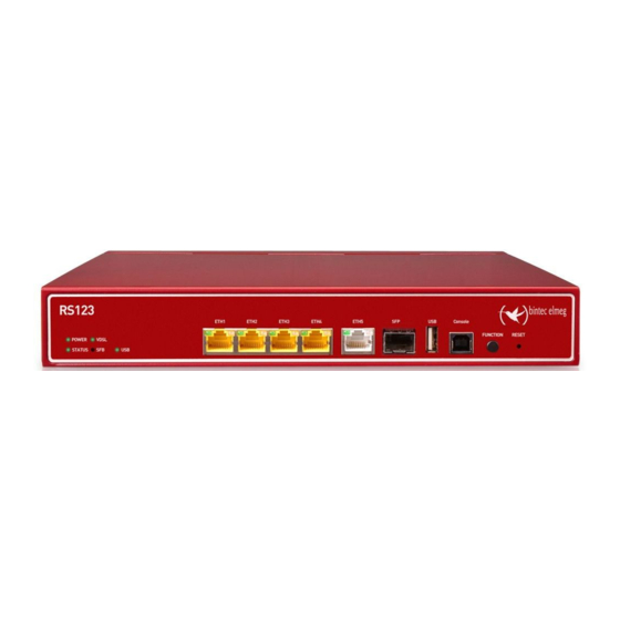
Bintec RS123, Bintec Rs123W, Bintec Rs353A and Bintec Rs353Aw
Setting up and Connecting
Connectors
Leds
Scope of Supply
General Product Features
Reset
Support Information
Cleaning
Pin Assignments
USB Console Interface
Ethernet Interface
Xdsl Interface
ISDN S0 Port
USB Interface
Inserting the SIM Card
Chapter 2 Basic Configuration
Presettings
IP Configuration
Software Update
System Requirements
Preparation
Gathering Data
Configuring a PC
Modify System Password
Setting up an Internet Connection
Internet Connection over Internal Xdsl Modem
Internet Connection over UMTS/LTE
Other Internet Connections
Testing the Configuration
Setting up Wireless LAN
Software Update
Chapter 3 Access and Configuration
Access Options
Access Via LAN
Access Via the Console Interface
Access over ISDN
Login
User Names and Passwords in Ex Works State
Logging in for Configuration
Configuration Options
GUI (Graphical User Interface)
SNMP Shell
Chapter 4 Assistants
Chapter 5 System Management
Status
Global Settings
System
Passwords
Date and Time
System Licences
Interface Mode / Bridge Groups
Interfaces
Administrative Access
Access
Ssh
Snmp
Remote Authentication
Radius
Tacacs
Options
Configuration Access
Access Profiles
Users
Certificates
Certificate List
Crls
Certificate Servers
Chapter 6 Physical Interfaces
Ethernet Ports
Port Configuration
ISDN Ports
ISDN Configuration
MSN Configuration
DSL Modem
DSL Configuration
Umts/Lte
Chapter 7 LAN
IP Configuration
Interfaces
Vlan
Vlans
Port Configuration
Administration
Chapter 8 Wireless LAN
Wlan
Radio Settings
Wireless Networks (VSS)
Client Link
Bridge Links
Administration
Basic Settings
Configuration
WLAN - Configuration Example
Chapter 9 Wireless LAN Controller
Wizard
Basic Settings
Radio Profile
Wireless Network
Start Automatic Installation
Controller Configuration
General
Slave AP Autoprofile
Slave AP Configuration
Slave Access Points
Radio Profiles
Wireless Networks (VSS)
Monitoring
WLAN Controller
Slave Access Points
Active Clients
Wireless Networks (VSS)
Client Management
Neighbor Monitoring
Neighbor Aps
Rogue Aps
Rogue Clients
Maintenance
Firmware Maintenance
Chapter 10 Networking
Routes
Ipv4 Route Configuration
Ipv6 Route Configuration
Ipv4 Routing Table
Ipv6 Routing Table
Options
Ipv6 General Prefixes
General Prefix Configuration
Nat
NAT Interfaces
NAT Configuration
NAT - Configuration Example
Load Balancing
Load Balancing Groups
Special Session Handling
Load Balancing - Configuration Example
Qos
Ipv4/Ipv6 Filter
Qos Classification
Qos Interfaces/Policies
Access Rules
Access Filter
Rule Chains
Interface Assignment
Drop in
Drop in Groups
Chapter 11 Routing Protocols
Rip
RIP Interfaces
RIP Filter
RIP Options
Chapter 12 Multicast
General
General
Igmp
Igmp
Options
Forwarding
Chapter 13 WAN
Internet + Dialup
Default Route
Pppoe
Pptp
Pppoa
Isdn
Umts/Lte
IP Pools
Atm
Profiles
Service Categories
OAM Controlling
Real Time Jitter Control
Controlled Interfaces
Chapter 14 VPN
Ipsec
Ipsec Peers
Phase-1 Profiles
Phase-2 Profiles
XAUTH Profiles
IP Pools
Options
L2Tp
Tunnel Profiles
Users
Options
Pptp
PPTP Tunnels
Options
IP Pools
Gre
GRE Tunnels
Chapter 15 Firewall
Policies
Ipv4 Filter Rules
Ipv6 Filter Rules
Options
Interfaces
Ipv4 Groups
Ipv6 Groups
Addresses
Address List
Groups
Services
Service List
Groups
Configuration
SIF - Configuration Example
Chapter 16 Voip
Sip
Options
Rtsp
RTSP Proxy
Chapter 17 Local Services
Dns
Global Settings
DNS Servers
Static Hosts
Domain Forwarding
Dynamic Hosts
Cache
Statistics
Https
HTTPS Server
Dyndns Client
Dyndns Update
Dyndns Provider
DHCP Server
IP Pool Configuration
DHCP Configuration
IP/MAC Binding
DHCP Relay Settings
DHCP - Configuration Example
Dhcpv6 Server
Dhcpv6 Server
Dhcpv6 Global Options
Stateful Clients
Stateful Clients Configuration
Web Filter
General
Filter List
Black / White List
History
CAPI Server
User
Options
Scheduling
Trigger
Actions
Options
Configuration Example - Time-Controlled Tasks (Scheduling)
Surveillance
Hosts
Interfaces
Ping Generator
ISDN Theft Protection
Options
Upnp
Interfaces
General
Hotspot Gateway
Hotspot Gateway
Options
Wake-On-LAN
Wake-On-LAN Filter
WOL Rules
Interface Assignment
Brrp
Virtual Routers
VR Synchronisation
Options
Chapter 18 Maintenance
Log out Users
Diagnostics
Ping Test
DNS Test
Traceroute Test
Software &Configuration
Options
Reboot
System Reboot
Factory Reset
Chapter 19 External Reporting
Syslog
Syslog Servers
IP Accounting
Interfaces
Options
Alert Service
Alert Recipient
Alert Settings
Snmp
SNMP Trap Options
SNMP Trap Hosts
Sia
Advertisement
Quick Links
1
Setting up and Connecting
2
Ip Configuration
Download this manual
Manual
bintec elmeg GmbH
Manual
bintec RS Series
New Generation
Copyright© Version 10.1.4 (SVN4082), 2016 bintec elmeg GmbH
bintec RS Series
1
Table of
Contents
Previous
Page
Next
Page
1
2
3
4
5
Advertisement
Table of Contents
Need help?
Do you have a question about the RS123 and is the answer not in the manual?
Ask a question
Questions and answers
Related Manuals for BinTec RS123
Network Router BinTec RV120-4G User Manual
Rv series (583 pages)
Network Router BinTec RS353a Manual
Rs series (620 pages)
Network Router BinTec RS353aw Manual
Rs series (620 pages)
Network Router BinTec X4100 User Manual
Bintec extendible multiprotocol router user's guide (474 pages)
Network Router BinTec X1000 User Manual
Internet access router (456 pages)
Network Router BinTec X4000 User Manual
(498 pages)
Network Router BinTec X3200 User Manual
(419 pages)
Network Router BinTec VICAS User Manual
(202 pages)
Network Router BinTec BinGO Plus Quick Install Manual
(2 pages)
Network Router BinTec BIANCA/BRICK-XL2 Getting Started
(36 pages)
Network Router BinTec BIANCA/BRICK XS Quick Install Manual
(2 pages)
Network Router bintec 4Ge-LE Quick Start Manual
(2 pages)
Network Router BinTec XGeneration X2301 Quick Install Manual
(22 pages)
Network Router BinTec elmeg T484 Operating Instructions Manual
(85 pages)
Network Router BinTec X2250 Technical Data Manual
(14 pages)
Network Router BinTec BIANCA/BRI Getting Started
(34 pages)
This manual is also suitable for:
Rs123w
Rs353aw
Rs353a
Table of Contents
Save PDF
Print
Rename the bookmark
Delete bookmark?
Delete from my manuals?
Login
Sign In
OR
Sign in with Facebook
Sign in with Google
Upload manual
Upload from disk
Upload from URL


Need help?
Do you have a question about the RS123 and is the answer not in the manual?
Questions and answers