Table of Contents
Advertisement
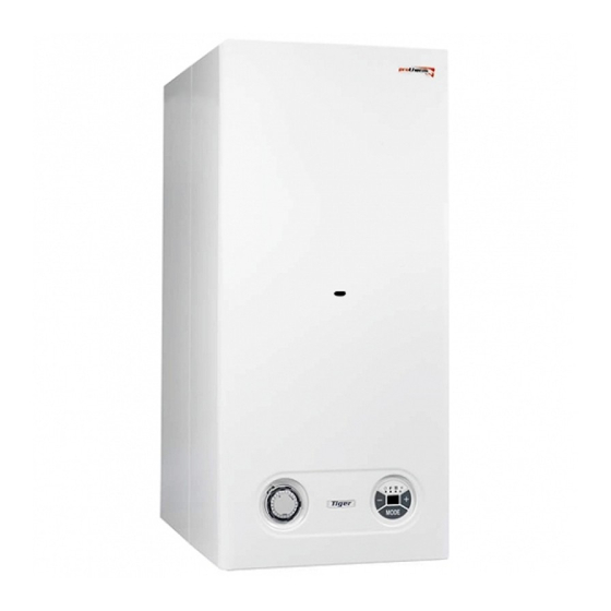
Protherm Tiger 24 (12) KTZ / 24 (12) KOZ
The boiler Serial No. is shown on the plate which is attached at the rear of the control
panel. The control panel is accessible after removing the front cover.
In the "Operating Guide" section you will find a description of the boiler's main functions
and guidelines how to handle the boiler safely. The "Installation Guide" section is intended
Table of contents
Introduction ............................................2
Controls and signals ..............................4
Selecting Read mode ............................5
Selecting Setup mode ...........................5
Error codes and troubleshooting ...........9
Boiler control .......................................10
Protective functions .............................12
Service and maintenance ...................13
Warranty and warranty conditions .......14
Technical parameters .......................... 15
Boiler working diagram ........................ 18
Supplied By www.heating spares.co Tel. 0161 620 6677
for qualified personnel only.
Introduction ..........................................19
Content of delivery ...............................21
Preparing for installation ......................22
Installing the boiler ...............................23
Air supply and flue gases removal .......27
Electrical wiring ....................................32
1
Advertisement
Table of Contents

Related Manuals for Protherm Tiger 24 (12) KTZ


Summary of Contents for Protherm Tiger 24 (12) KTZ
-
Page 1: Table Of Contents
Protherm Tiger 24 (12) KTZ / 24 (12) KOZ The boiler Serial No. is shown on the plate which is attached at the rear of the control panel. The control panel is accessible after removing the front cover. In the “Operating Guide” section you will find a description of the boiler’s main functions and guidelines how to handle the boiler safely. - Page 2 24 (12) KOZ / v.17 Wall-hang combined boiler Output 9,5 - 23 (3,5 - 11,5) kW Hot water heat in tank www.protherm.sk Protherm spol. s r.o. Your service: Pplk. Pľjušťa 45 v e r s i o n 909 01 Skalica Tel.: 034 6966 101...
-
Page 3: Introduction
Introduction 1. The boiler and all associated equipment check whether boiler settings on the ma- must be installed and used in accordan- nufacturing tag correspond to the local ce with the installation design, all appli- fuel (gas) supply parameters, or let the cable legal regulations, technical stan- person who will install or put the boiler dards and with the manufacture’s in-... - Page 4 Situations might occur in practice, when led appliances, efficiency of hot-water the following essential measures must be boilers fired by liquefied or gaseous fuels adopted: electrical equipment with low voltage and electromagnetical compatibility. Fur- • prevent the boiler from (even accidental- thermore it complies with Slovak techni- ly) being turned on while conducting in- cal specifications STN EN 50 165, STN...
-
Page 5: Operating Guide
Operating Guide Operating Guide Controls and signals Main switch Main switch The main switch (Fig. 1) is used to switch the boiler on or off. The main switch is si- tuated on the bottom side of the boiler in line with the control panel. Please note: The boiler must be put into operation and switched on for the first time by an authorised service organisation. -
Page 6: Selecting Read Mode
Selecting Read mode Displaying HeW temperature Displaying HeW pressure After turning the boiler Pressing and holding de- on with the main switch, pressed the but- the current heating water ton will display HeW pres- temperature will appear sure (bar) in the system on the display. - Page 7 HoW tank timer switch 12 12 Fig. 3 Setting time intervals for water tank the left side of the dial, is used to select 3 permanent modes. Mode “0” is used for heating permanent shutdown of HoW tank he- The Tiger boiler enables setting of HoW ating.
- Page 8 Equithermal mode – curve Equithermal mode – reference steepness temperature shift Press the button If the previous parameter repeatedly until the dis- “E” was confirmed by the play shows the letter E button, the dis- with parameter 0 to 9. Use play will show parameter buttons to select...
- Page 9 Boiler function flowchart Fig. 5 Supplied By www.heating spares.co Tel. 0161 620 6677...
-
Page 10: Error Codes And Troubleshooting
Error codes and troubleshooting Loss of HeW pressure - F0 Other errors – F2 – F8 Loss of HeW pressure If errors F2 – F8 are (under 0.6 bar) in the displayed call an autho- system. The boiler is rized service. The LED automatically shut down at symbol flashes. -
Page 11: Starting The Boiler And Turning It Off
Starting the boiler up and turning it off Starting the boiler up by the emergency thermostat interven- tion, the boiler cannot be unblocked by Important: Putting the boiler into operati- the main switch (RESET). Unblocking the on and starting it up for the first time must emergency thermostat must be done by be done by an authorised service only! an authorised service technician, and this... - Page 12 rature of the water in the system) which 2. Select “equithermal mode – curve stee- will be capable of covering thermal losses pness” and set symbol E5 – see pg. 7. of the building even in low outdoor tempe- 3. Select “equithermal mode – reference ratures.
-
Page 13: Protective Functions
Example: Select curve E5. At an outdoor Setting boiler output temperature of -10 °C the boiler provides The factory setting of the boiler output is the heating system with a temperature of 15 kW to the heating system. During hea- 70 °C. -
Page 14: Service And Maintenance
Pump run-down call an authorised service organisation. If the heating system repeatedly looses Pump run-down is factory set to 45 se- pressure, consult your service organisa- conds after termination of the command tion. from the room control unit. If the boiler is Important: above-mentioned run without a room control unit, the pump... -
Page 15: Warranty And Warranty Conditions
(even during boi- ler operation) Fig. 6 Warranty and warranty conditions PROTHERM Tiger 24 (12) KTZ and 24 (12) KOZ gas boilers are covered by warranty defined in the Warranty Certificate, the Ser- vice Book and other conditions specified in... -
Page 16: Technical Parameters
Technical parameters 24 (12) KOZ Tiger 24 KOZ Tiger 12 KOZ Category ..........II 2H3P Version . - Page 17 Technical parameters 24 (12) KTZ Tiger 24 KTZ Tiger 12 KTZ Category ..........II 2H3P Version .
- Page 18 Boiler connection dimensions 1. HeW outlet G3/4“ 2. HoW outlet G1/2“ 3. Gas inlet G1/2“ 4. HoW inlet G1/2“ 5. HeW inlet G3/4“ 6. Tank drain Fig. 7 Připojovací rozměry kotle Usable gauge pressure to the system Fig. 8 Supplied By www.heating spares.co Tel. 0161 620 6677...
-
Page 19: Boiler Working Diagram
Function schematic diagram 1*. Combustion gas thermostat 9. HoW draining valve 19. Bypass 1. Air manostat 10. HeW safety valve 20. 3-way motor valve 2*. Draught valve 11. HeW inlet 21. Draining valve 2. Fan 12. HoW inlet 22. Pressure sensor 3. -
Page 20: Installation Guide
Installation Guide Installation Guide Introduction The PROTHERM Tiger 24 (12) KTZ a 24 (12) cium and magnesium concentration greater KOZ boilers are compatible with common typ- than 1.8 mmol/l, it is useful to implement other es of HoW heating systems and heating radi- “non-chemical”... - Page 21 The manipulation (free) space left around ding to the boiler throat. It is forbidden to the boiler must be sufficient for a person place into the flue duct an objects obstruc- to work on it safely with bare hands and ting the flow of combustion gasses (e.g.
-
Page 22: Boiler Delivery
Content of delivery Boiler delivery PROTHERM Tiger 24 (12) KTZ and 24 Content of delivery (12) KOZ boilers are delivered completely assembled and functionally tested. The delivery contains (Fig. 11): 1. Boiler 2. Operations and Installation Guide 3. Service Book Záručný... -
Page 23: Preparing For Installation
Preparing for installation sential to clean the system thoroughly. In Distribution pipes old systems it is necessary to remove all Nominal pipe inside diameter is chosen in sludge settled at the bottom of the heating the usual way based on the pump chara- radiators (particularly in gravity systems). -
Page 24: Installing The Boiler
Thermostatic radiator valves Domestic HoW system If a room control unit is installed, at least The HoW pressure must be 1 to 6 bars. If one of the radiators in the reference room the pressure exceeds 6 bars, a reduction must be without a thermostatic valve. - Page 25 Mounting the boiler Fig. 12 Operating pressure in the heating If the heating system is already filled, shut the HeW valves located underneath the system boiler and, using the drainage valve, relie- The heating system (measured on the ve the boiler from pressure. Then you can boiler) must be filled at least to the hyd- check the expansion vessel pressure and raulic pressure of 1 bar (corresponds to...
- Page 26 (size Connecting gas supply 18 × 10 × 2). The Tiger 24 (12) KTZ a 24 (12) KOZ After completing the gas supply connecti- – natural gas boilers are designed to be on to the boiler, the coupling must be tho- fuelled by natural gas of nominal pressu- roughly checked for potential gas leaks.
- Page 27 from switching on the main switch the boi- Draining water from the heating system and ler will be shut down, the boiler display will refilling it again and the follow-up operati- show F0, flashing LED at symbols ons (bleeding, adjusting expansion vessel) are not covered by the boiler’s warranty.
-
Page 28: Air Supply And Flue Gases Removal
Air supply and combustion gas removal for KTZ boilers Important: When exceeding lengths In the case of model KTZ combustion ga- prescribed in Table 2, a combustion gas ses must be removed and fresh air sup- diffuser (screen) must be located at the plied through special dual tubing. - Page 29 from opposite directions,the minimum ver- Method C tical distance between them must be 0.60 m. Outlets of routes terminated in a com- mon dual chimney must never be fitted with end pieces (used in routes dischar- ging to free space)! Both route sections (the outside –...
- Page 30 (or special chimney or shaft) - if the tubing a = 1.5 m, g = 5.0 m, c = 5.0 m. does not contain such pieces, it must be If g < 5.0 m, zones overlap, but the ove- supplemented (combined with) compo- rall zone width of 8 m must be maintained nents from other tubes (e.g.
- Page 31 Fig. 22a - Dual outlet in horizontal con- figuration on a straight external wall Dual outlet in vertical configuration Minimum distances with dual outlet in ver- tical configuration on a straight external wall should be: a = 0.5 m; b = 1.0 m; c = 5.0 m; a1 depen- ding on x as follows: x ≥...
- Page 32 Safety measures e.g. tunnels, subways, etc. With respect to these principles of prohibi- The distance of flammable materials from ted location of flues, the inlet termination the flue section of the separated tubing of air supply must also be evaluated inde- must be such that the surface tempera- pendently.
-
Page 33: Electrical Wiring
Fig. 23 Rebuilding the boiler for alternative fuel (propane) for propane operation is part of the kit for The basic design of Protherm Tiger 24 (12) KTZ and 24 (12) KOZ boilers is made changing the boiler from natural gas to to run with natural gas. -
Page 34: Boiler Rebuilding For Alternative Fuel Type .32 Boiler Electric Diagram 24 (12) Koz
Supplied By www.heating spares.co Tel. 0161 620 6677... -
Page 35: Boiler Electric Diagram 24 (12) Ktz
Supplied By www.heating spares.co Tel. 0161 620 6677... - Page 36 Supplied By www.heating spares.co Tel. 0161 620 6677...
Need help?
Do you have a question about the Tiger 24 (12) KTZ and is the answer not in the manual?
Questions and answers