Table of Contents
Advertisement
Quick Links
Advertisement
Table of Contents

Related Manuals for BCM Advanced Research MX310HD


Summary of Contents for BCM Advanced Research MX310HD
- Page 1 MX310HD User’s Manual MX310HD Intel® H310 PCH Supports Coffee Lake (8th Gen)/ Coffee Lake Refresh (9th Gen) i7/i5/i3/Pentium processors (Supports “up to 6 Cores” and “up to TDP 65W” type processors only) Mini-iTX Motherboard User’s Manual Edition 1.01 – July, 2019...
- Page 2 Copyright Notice Copyright © 2011 BCM Advanced Research, ALL RIGHTS RESERVED. No part of this document may be reproduced, copied, translated, or transmitted in any form or by any means, electronic or mechanical, for any purpose, without the prior written permission of the original manufacturer.
- Page 3 MX310HD User’s Manual Disclaimer BCM Advanced Research reserves the right to make changes, without notice, to any product, including circuits and/or software described or contained in this manual in order to improve design and/or performance. BCM Advanced Research assumes no responsibility or liability for the use of the described...
- Page 4 MX310HD User’s Manual A Message to the Customer BCM Customer Services Each and every BCM product is built to the most exacting specifications to ensure reliable performance in the harsh and demanding conditions typical of industrial environments. Whether your new BCM device is destined for the laboratory or the factory floor, you can be assured that your product will provide the reliability and ease of operation for which the name BCM has come to be known.
- Page 5 MX310HD User’s Manual Product Warranty BCM warrants to you, the original purchaser, that each of its products will be free from defects in materials and workmanship for two years from the date of purchase. This warranty does not apply to any products which have been repaired or altered by persons other than repair personnel authorized by BCM, or which have been subject to misuse, abuse, accident or improper installation.
- Page 6 MX310HD User’s Manual Manual Objectives This manual describes in detail the BCM MX310HD Main board. We strongly recommend that you study this manual carefully before attempting to interface with this mainboard or change the standard configurations. Whilst all the necessary information is available in this manual we would recommend that unless you are confident, you contact your supplier for guidance.
-
Page 7: Table Of Contents
MX310HD User’s Manual Contents Chapter 1: System Setup ....................Welcome! ............................15 Packing Contents .......................... 15 Before you proceed ........................16 Mainboard Overview ........................17 1.4.1 Mounting Holes ..........................17 1.4.2 Mainboard Layout ......................... 18 1.4.3 Layout Content List ........................19 1.4.3.1... - Page 8 MX310HD User’s Manual 1.9.9 Serail Port Connector: J_COM1, J_COM2 ................... 42 1.9.10 LVDS Header: J_LVDS ......................... 42 1.9.11 LVDS Panel Backlight Connector: J_BACKLIGHT ............... 43 1.9.12 SPI Header: J_SPI ........................43 1.9.13 I2S Header: J_I2S ......................... 44 1.9.14 I2C Header: J_I2C ........................44 1.9.15...
- Page 9 MX310HD User’s Manual 3.7.1.4 Intel® Speedstep .......................... 59 3.7.1.5 C States ............................59 3.7.1.6 Enhanced C-States ........................59 3.7.1.7 Package C State Limit ........................59 3.7.2 PCH-FW Configuration ......................... 60 3.7.3 Trusted Computing ........................60 3.7.4 ACPI Settings ..........................60 3.7.4.1...
- Page 10 MX310HD User’s Manual 3.8.1.1 Memory Configuration ........................66 3.8.1.1.1 Max TOLUD ..........................66 3.8.1.2 Graphics Configuraiton ......................... 66 3.8.1.2.1 Primary Display ..........................66 3.8.1.2.2 Internal Graphics ........................... 66 3.8.1.2.3 DVMT Pre-Allocated ........................66 3.8.1.2.4 DVMT Total Gfx Mem ........................66 3.8.1.3...
- Page 11 MX310HD User’s Manual 3.11.4 Load Optimized Default ........................ 71 Chapter 4: Application Note ......................72 Windows 10 Drivers Installation ....................72 Display through PCIe video card (installed on "J_PCIEX4" slot) ..........73 PXE Boot ............................74...
- Page 12 MX310HD User’s Manual Mainboard Specifications Model MX310HD Processor Intel® H310 PCH Supports Coffee Lake (8th Gen)/ Coffee Lake Refresh (9th Gen) i7/i5/i3/Pentium processors (Supports “up to 6 Cores” and “up to TDP 65W” type processors only) Chipset Intel® H310 PCH 2x 260-pins SODIMM sockets support 1.2V, Non-ECC, Un-buffered DDR4-2400...
- Page 13 MX310HD User’s Manual Onboard I/O Headers SATA 2 x Std. SATA III Connectors 1 x SATA Power Header 1 x USB2.0 Header (2 ports/header) 1 x USB3.0 Header (2 ports/header) RS232 2 x Headers Front Audio 1 x Header Amplifier...
- Page 14 MX310HD User’s Manual Power & Connector 1 x 4 pin ATX Connector (12V-24V Wide Range, Max. current ~8A) 1 x DC Connector (12V-24V Wide Range DC-In) For +12V AC adapter, Max. current ~8A. For +19V AC adapter, Max. current ~8A.
-
Page 15: Chapter 1: System Setup
If any of the items listed below is damaged of missing, please contact with your vendor. 1.2 Packing Contents • Mainboard • 1 x MX310HD • Cable • 1 x SATA Power Cable • Accessories • 1 x MX310HD I/O Shield... -
Page 16: Before You Proceed
MX310HD User’s Manual Before you proceed Take note of the following precautions before you install mainboard components or change any mainboard settings. • Unplug the power cord from the wall socket before touching any component inside the system. • Use a grounded wrist strap or touch a safely grounded object or to a metal object, such as the power supply case, before handling components to avoid damaging them due to static electricity. -
Page 17: Mainboard Overview
MX310HD User’s Manual 1.4 Mainboard Overview Before you install the mainboard, study the configuration of your chassis to ensure that the mainboard fits into it. Make sure to unplug the power cord before installing or removing the mainboard. Failure to do so can cause you physical injury and damage mainboard components. -
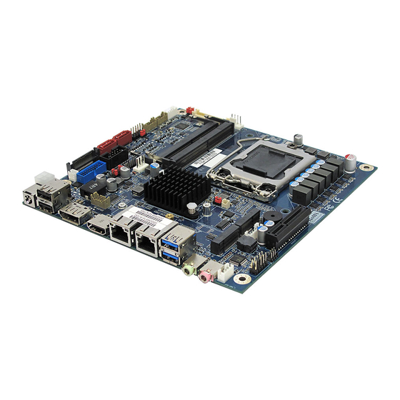
Page 18: Mainboard Layout
MX310HD User’s Manual 1.4.2 Mainboard Layout... -
Page 19: Layout Content List
MX310HD User’s Manual 1.4.3 Layout Content List • 1.4.3.1 Slots Label Function Note Page J_SODIMM1 260-pin DDR4 SODIMM slot 1 J_SODIMM2 260-pin DDR4 SODIMM slot 2 J_M2E E-Key Supports WIFI Cards in 2230 J_M2M M-Key Supports SATA Type SSDs in... -
Page 20: Internal Headers
MX310HD User’s Manual • 1.4.3.3 Internal Headers Label Function Note Page J_ATX-IN 12V ATX Power Connector 2x 2 header, 12V-24V Wide Range, Max. current ~8A J_CPU-FAN CPU Fan Connector 4 x 1 wafer, Pitch 2.54mm J_SYS-FAN System Fan Connector 4 x 1 wafer, Pitch 2.54mm J_SATA3-1 Serial ATA 3.0 Connectors 1, 2... -
Page 21: Back Panel Connectors
MX310HD User’s Manual • 1.4.3.4 Back Panel Connectors (Rear I/O) Label Function Note Page J-DC-IN DC Adapter Connector The port is for an AC adapter (12V-24V Wide Range DC-In) . For +12V AC adapter, Max. current ~8A. . For +19V AC adapter, Max. -
Page 22: Central Processing Unit (Cpu)
MX310HD User’s Manual Central Processing Unit (CPU) This mainboard supports the Intel® LGA1151 socket for Intel® Core™ i5/i3/Pentium Coffee Lake processors in LGA-1151 package. • Your boxed Intel® LGA1151 processor package should come with installation instructions for the CPU, fan, heatsink, and the retention assembly. -
Page 23: Installing The Cpu
MX310HD User’s Manual 1.5.1 Installing the CPU The CPU installation related information. 1. Locate the CPU socket (LGA1151 Socket) on the mainboard. 2. Unlatch the “CPU Socket Lever” by pressing the lever down and move it away from the main structure of the socket. - Page 24 MX310HD User’s Manual 3. Lift the load lever up in the direction of the arrow to a 135° angle, so the metal “CPU Socket Cover” can also be lifted. 4. The CPU socket has a plastic protection cap installed on it (black color, a.k.a. “CPU Socket Cover”, or “PnP cap”) in order to protect the socket pins from damage.
- Page 25 MX310HD User’s Manual 5. There are two notches on the CPU itself (one on each side), and there are two “Socket Alignment keys” on the CPU socket as well. Line up the two CPU notches with the “Socket Alignment Keys” on the socket, and insert the CPU into the CPU socket slowly.
- Page 26 MX310HD User’s Manual 7. Close the “CPU Socket Cover” by lowering down the “CPU Socket Lever”. Make sure the “CPU Socket Front Plates” are sliding underneath the “Shoulder Screw Cap”. 8. Secure the “CPU Socket Cover” by keep pressing down the “CPU Socket Lever” and move it toward and underneath the “Load Plate Tab”.
-
Page 27: Installing The Cpu Heatsink And Fan
MX310HD User’s Manual 1.5.2 Installing the CPU Heatsink and Fan The Intel LGA1151 processor requires a specially designed heatsink and fan assembly to ensure optimum thermal condition and performance. • When you purchase a boxed Intel® processor, the package includes the CPU fan and heatsink assembly. - Page 28 MX310HD User’s Manual Push down two fasteners at a time in a diagonal sequence to secure the heatsink and fan assembly in place 3. Connect the CPU fan cable to the connector on the mainboard labeled “J_CPU-FAN”. A. Do not forget to connect the CPU fan connector. Insufficient air flow inside the system chassis may damage the mainboard components.
-
Page 29: Uninstalling The Cpu Heatsink And Fan
MX310HD User’s Manual 1.5.3 Uninstalling the CPU Heatsink and Fan. To uninstall the CPU heatsink and fan: 1. Disconnect the CPU fan cable from the connector on the mainboard. 2. Rotate each fastener counterclockwise. 3. Pull up two fasteners at a time in a diagonal sequence to disengage the heatsink and fan assembly... - Page 30 MX310HD User’s Manual 4. Rotate each fastener clockwise to ensure correct orientation when reinstalling. The narrow end of the groove should point outward after resetting. (The photo shows the groove shaded for emphasis.)
-
Page 31: System Memroy
MX310HD User’s Manual System Memory 1.6.1 Overview The mainboard comes with two 260-pin Double Data Rate 4 (DDR4) Dual Inline Memory Modules (SODIMM) sockets. DDR4 SDRAM, an abbreviation for double data rate fourth generation synchronous dynamic random-access memory, is a type of synchronous dynamic random-access memory (SDRAM) with a high bandwidth (“double data rate”) interface. -
Page 32: Memory Configurations
MX310HD User’s Manual 1.6.2 Memory Configurations The MX310HD board supports 1.2V, Non-ECC, Un-buffered, 260-pins DDR4-2400 (PC4-19200, 2400MHz) SODIMM up to 32GB (16GB maximum/slot). • When there is only one DDR4 memory module being installed, it is recommended to install it on “J_SODIMM1” slot. -
Page 33: Installing The Ddr4 Sodimm
MX310HD User’s Manual 1.6.3 Installing the DDR4 SODIMM Make sure to unplug the power supply before installing or removing SODIMMs, or other peripherals from the system. Failure to do so may cause severe damage to both the mainboard and the peripherals. -
Page 34: Removing The Ddr4 Sodimm
MX310HD User’s Manual 1.6.4 Removing the DDR4 SODIMM Follow these steps to remove a SODIMM. 1. Press the two ejector tables on the slot outward simultaneously 2. Remove the SODIMM module from the socket. Hold the SODIMM module gently when pressing the ejector tabs. The SODIMM might... -
Page 35: Power Supply
2. Use of a PSU with adequate power output is recommended when configuring a system with more power-consuming devices. The system may become unstable or may not boot if the power supply wattage is inadequate. 3. The MX310HD board can be power on EITHER through: A. -
Page 36: Back Panel (Rear I/O Ports)
MX310HD User’s Manual Back Panel (Rear I/O Ports) 1.8.1 Back Panel Connectors Item Name Function Description J_DC-IN AC adapter Connector This port is for an AC adapter (12V-24V Wide Range DC-In) For +12V AC adapter, Max. current ~8A. For +19V AC adapter, Max. current ~8A. - Page 37 MX310HD User’s Manual Item Name Function Description J_LAN2 Gigabit LAN This port allows Gigabit connection to a Local Area Network (RJ-45) Connectors (LAN) through a network hub. Refer to the table below for the LAN port LED indications. ACT/Link LED...
-
Page 38: Connectors/Headers
MX310HD User’s Manual Connectors/ Headers 1.9.1 Front Panel Connectors: J_FR-PANEL These connectors are for electrical connections to the front panel switches and LEDs. The “J_FR-PANEL” connector is compliant with Intel® Front Panel I/O Connectivity Design Guide. 1.9.2 Serial ATA 3.0 Connectors: J_SATA3-1, J_SATA3-2 SATA ports “J_SATA3-1”... -
Page 39: Serail Ata Power Connector: J_Sata-Pwr
MX310HD User’s Manual 1.9.3 Serial ATA Power Connector: J_SATA-PWR This connector provides power connection to SATA device attached at connectors “J_SATA3-1” or “J_SATA3-2”. 1.9.4 CPU & System Fan Connectors: J_CPU-FAN, J_SYS-FAN The 4-pins fan power connector supports system cooling fan with +12V. In order to take the... -
Page 40: Front Panel Audio Connectors: J_Fr-Audio
MX310HD User’s Manual 1.9.5 Front Panel Audio Connector: J_FR-AUDIO This connector is prepared for a chassis-mounted front panel audio I/O module that supports HD Audio standard. Connect one end of the front panel audio I/O module cable to this connector. -
Page 41: Front Usb3.0 Headers: J_Usb3-12
MX310HD User’s Manual 1.9.7 Front USB3.0 Headers: J_USB3-12 This header provides two USB3.0 connections (An USB3.0 cable required). 1.9.8 Front USB2.0 Headers: J_USB2-56 This header provides two USB2.0 connections (An USB2.0 cable required). Be sure the pins of USB+5V and GND signals are connected to the corresponding USB2.0 headers correctly. -
Page 42: Serail Port Connector: J_Com1, J_Com2
MX310HD User’s Manual 1.9.9 Serial Port Connector: J_COM1, J_COM2 These headers provide serial connections on COM1, COM2 respectively. 1.9.10 LVDS Header: J_LVDS This header provides connection to LVDS type panels (800x600 18-bit Single channel to 1920x1200 24-bit dual channel). -
Page 43: Lvds Panel Backlight Connector: J_Backlight
MX310HD User’s Manual 1.9.11 LVDS Panel Backlight Connector: J_BACKLIGHT This header provides connection for LVDS panel backlight control connections. 1.9.12 SPI Header: J_SPI This header provides SPI signal connections. -
Page 44: I2S Header: J_I2S
MX310HD User’s Manual 1.9.13 I2S Header: J_I2S This header provides I2S signal connections. 1.9.14 I2C Header: J_I2C This header provides I2C signal connections. -
Page 45: Gpio Header: J_Gpio
MX310HD User’s Manual 1.9.15 GPIO Header: J_GPIO This header provides 8-bit general purpose I/O (GPIO) connections to external device. Customer can write their own monitoring program to monitor the status of external device connected with this header. 1.9.16 Chassis Intrusion Header: J_CHASSIS... -
Page 46: Jumpers
MX310HD User’s Manual 1.10 Jumpers 1.10.1 ATX/AT Mode Selection: This header provides the option to boot the system in the form of ATX mode (default) or AT mode. When the system is set in AT mode, the system power on/off will be controlled directly by the power switch on the power supply. -
Page 47: Com1 Ring-In/ +12V/ +5V Select: Jp5
MX310HD User’s Manual 1.10.3 COM1 Ring-In/ +12V/ +5V Select: JP5 This header provides the options of selecting the COM port function as “Ring-in” (default), or “+5V”, or “+12V”. 1.10.4 COM2 Ring-In/ +12V/ +5V Select: JP6 This header provides the options of selecting the COM port function as “Ring-in” (default), or... -
Page 48: Lvds Brightness Mode Select: Jp2
MX310HD User’s Manual 1.10.5 LVDS Brightness Mode Select: JP2 This header provides the options of selecting the connected LVDS panel brightness mode either in “PWM mode” (default) or “DC mode”. (The mode selected is depending on the type of LVDS panel inverter used). -
Page 49: Clear Cmos Jumper: Jp3
For normal state (default), the jumper is set on pin location 1 and 2. To clear the CMOS, disconnect all power connections to MX310HD first, then set the JP3 jumper to pin location 2 and 3 for at least 30 seconds while the system is disconnected from the power. -
Page 50: The Expansion Slots
MX310HD User’s Manual 1.11 The Expansion Slots In the future, you may need to install expansion cards. The following sub-sections describe the expansion slots and the expansion cards that they support. Make sure to unplug the power cord before adding or removing expansion cards. -
Page 51: Pcie X4 Slot: J_Pcie4X
MX310HD User’s Manual 1.11.3 PCIe x4 Slot: J_PCIE4X The PCIe x4 slot supports PCIe x1, PCIe x4 cards (e.g. PCIe LAN cards), or some of the PCIe x16 video cards. -
Page 52: Sockets
MX310HD User’s Manual 1.11.4 M.2 Sockets 1.11.4.1 M.2 Socket (M-Key): J_M2M The “J_M2M” socket supports “M-Key”, SATA type SSDs in 2242 or 2280. 1.11.4.2 M.2 Socket (E-Key): J_M2E The “J_M2E” socket supports “E-Key”, WIFI cards in 2230. -
Page 53: Chapter 2: Starting Up The System
MX310HD User’s Manual Chapter 2: Starting Up the System Starting Up Your System After all connections are made, close your computer case cover. Be sure all the switches are off, and check that the power supply input voltage is set to the local voltage, usually in-put voltage is 220V∼240V or 110V∼120V depending on your country’s voltage used. - Page 54 MX310HD User’s Manual devices which are attached to the system will be displayed. Then you may select the desired first bootable device from this menu. Power off your computer: You must first exit or shut down your operating system before switch off the power switch.
-
Page 55: Chapter 3: Bios Setup
MX310HD User’s Manual Chapter 3: BIOS Setup BIOS Flash Related Procedure 1. After the BIOS is flashed, shut down the system. 2. Disconnect all power connections from power supply to the mainboard. 3. Clear the CMOS (For at least 30 seconds). -
Page 56: Entering Bios Setup Menu
MX310HD User’s Manual Entering BIOS Setup Menu Power on the computer and by pressing <DEL> immediately allows you to enter BIOS Setup Menu. If you are not able to enter the BIOS menu but you still wish to enter Setup, restart the system to try again by turning it OFF then ON or pressing the “RESET”... -
Page 57: Bios Menu Screen
MX310HD User’s Manual BIOS Menu Screen When entering the BIOS, the following screen appears. The BIOS menu screen displays the items that allow user to make changes to the system configuration. To access the menu items, press the up/down/right/left arrow key on the keyboard until the desired item is highlighted, then press [Enter] to... -
Page 58: Main Menu
MX310HD User’s Manual Main Menu This menu gives user an overview of the general system specifications, such as time, date etc. • BIOS Information Displays the auto-detected BIOS information. • System Date The date format is <Date>,<Month>,<Day>,<Year>. • System Time... -
Page 59: Advanced Menu
MX310HD User’s Manual Advanced Menu Select the “Advanced” tab from the BIOS menu screen to enter the Advanced BIOS Setup screen. NOTE: Take caution when change the settings of the Advanced menu items. Incorrect field values can cause the system not to function properly. -
Page 60: Pch-Fw Configuration
MX310HD User’s Manual 3.7.2 PCH-FW Configuration Configure management engine (ME) technology related parameters. 3.7.3 Trusted Computing Trusted computing (TPM) settings. By combining the onboard TPM 2.0 with TPM security software (provided by the third party), it will enhance the security level of the system. -
Page 61: Super Io Configurtion
MX310HD User’s Manual 3.7.5 Super IO Configuration System Super IO chip parameters. 3.7.5.1 Serial Port 1 Configuration Set parameters of serial port 1 (COM1). 3.7.5.2 Serial Port 2 Configuration Set parameters of serial port 2 (COM2). 3.7.5.3 WatchDog Count Mode Set the WatchDog Count in minutes or seconds. -
Page 62: Hw Monitor
MX310HD User’s Manual 3.7.6 HW Monitor Monitor hardware status. 3.7.6.1 Smart Fan Smart Fan function page. 3.7.6.1.1 Smart Fan Function Smart Fan function enable/disable. 3.7.6.1.2 Smart Fan Mode Configuration Setup the desired target temperatures for fans connected to fan headers “J_CPU-FAN”... -
Page 63: Usb Configuration
MX310HD User’s Manual 3.7.8 USB Configuration USB configuration parameters. 3.7.8.1 Legacy USB Support Enable legacy USB support. AUTO: Disables legacy support if no USB devices are connected. Disabled: Will keep USB devices available only for EFI applications. 3.7.8.2 XHCI Hand-off This is a workaround for OSes without XHCI hand-off support. -
Page 64: Network Stack Configuration
MX310HD User’s Manual 3.7.9 Network Stack Configuration Network Stack Settings. 3.7.9.1 Network Stack Enable/Disable UEFI Network Stack. 3.7.9.2 IPv4 PXE Support Enable/Disable IPv4 PXE boot support. If disabled, IPv4 PXE boot support will not be available. Note: Here is the procedure to setup the PXE with onboard LAN1 or LAN2. -
Page 65: Csm Configuration
MX310HD User’s Manual 3.7.10 CSM Configuration Enable/Disable, option ROM execution settings, etc. 3.7.10.1 CSM Support Enable/Disable CSM Support 3.7.10.2 Boot Option Filter This option controls Legacy/UEFI ROMs priority. -
Page 66: Chipset
MX310HD User’s Manual Chipset 3.8.1 System Agent (SA) Configuration System Agent (SA) Parameters 3.8.1.1 Memory Configuration Memory Configuration Parameters. 3.8.1.1.1 Max TOLUD TOLUD is Top of Lower Usable DRAM, this item is to select the max. TOLUD, can reserve enough MMIO manually. -
Page 67: Lvds Panel Type
MX310HD User’s Manual 3.8.1.3.2 LVDS Panel Type Select LCD panel type. 3.8.1.3.3 LCD Brightness Control Select LCD brightness control mode (The onboard jumper “JP4” also needs to be adjusted at the corresponding setting). 3.8.1.3.4 LVDS PWM Brightness Control Adjust Brightness of LVDS (from 1~ 255). -
Page 68: Restore Ac Power Loss
MX310HD User’s Manual 3.8.2.8 Restore AC Power Loss Specify what state to go to when power is re-applied after a power failure (G3 state). 3.8.2.9 GPIO Group Control Configure the digital GPIO pins. 3.8.2.10 Amplifier GAIN (db) Select Amplifier GAIN value. The volume through onboard header “J_AMP-OUT”. -
Page 69: Security
MX310HD User’s Manual Security Setup the administrator or user passwords, and secure boot related settings. -
Page 70: Boot
MX310HD User’s Manual 3.10 Boot Boot related configurations. 3.10.1 Setup Prompt Timeout Number of seconds to wait for setup activation key. (system post time). 3.10.2 Bootup NumLock State Select the keyboard NumLock state. 3.10.3 Quiet Boot Enable or disable quiet boot option. -
Page 71: Save & Exit
MX310HD User’s Manual 3.11 Save & Exit Save & Exit BIOS settings. 3.11.1 Save Changes and Exit Exit system setup after saving the changes. 3.11.2 Discard Changes and Exit Exit system setup without saving any changes. 3.11.3 Save Changes and Reset Reset the system after saving the changes. -
Page 72: Chapter 4: Application Note
It is recommended to load the MX310HD drivers with the following sequence: 1. Update Win10 to the latest version through Windows Update by connecting Ethernet cable to MX310HD onboard i211 LAN (Located next to the rear I/O USB3.0 ports (blue color USB ports)). -
Page 73: Display Through Pcie Video Card (Installed On "J_Pciex4" Slot)
(NOTE: If the installed PCIe video card is not being detected under device manager, it means this PCIe card is not compatible with MX310HD board). 10. Install the PCIe video card Win10 driver provided by PCIe video card manufacturer. -
Page 74: Pxe Boot
MX310HD User’s Manual PXE Boot 1. Enter BIOS. 2. Enter BIOS option “Advanced”->”Network Stack Configuration”; Enable “Network Stack”. 3. Set “Ipv4 PXE Support” to “Enabled”. 4. Save and Exit BIOS. 5. Reboot the system. 6. Enter BIOS option "Boot"->"UEFI Network Drive BBS Priorities"; choose the desired boot LAN.
Need help?
Do you have a question about the MX310HD and is the answer not in the manual?
Questions and answers