Table of Contents
Troubleshooting

Related Manuals for Miller XMT 650


Summary of Contents for Miller XMT 650
- Page 1 OM-291052A 2022-05 Processes Multiprocess Welding Description Arc Welding Power Source ® ArcReach Polarity Reversing 460V OWNER’S MANUAL For product information, Owner’s Manual translations, and more, visit www.MillerWelds.com...
- Page 2 We know you don’t have time to do it any other way. That’s why when Niels Miller first started building arc welders in 1929, he made sure his products offered long-lasting value and superior quality.
-
Page 3: Table Of Contents
TABLE OF CONTENTS SECTION 1 – SAFETY PRECAUTIONS – READ BEFORE USING..............1 Symbol Usage . -
Page 4: Section 1 - Safety Precautions - Read Before Using
SECTION 1 – SAFETY PRECAUTIONS – READ BEFORE USING Protect yourself and others from injury—read, follow, and save these important safety precautions and operating instructions. 1-1. Symbol Usage DANGER! – Indicates a hazardous situation which, if not avoided, will result in death or serious injury. The possible hazards are shown in the adjoining symbols or explained in the text. - Page 5 HOT PARTS can burn. WELDING can cause fire or explosion. � Do not touch hot parts bare handed. � Allow cooling period before working on equipment. Welding on closed containers, such as tanks, drums, or pipes, can cause them to blow up. �...
-
Page 6: Additional Hazards For Installation, Operation, And Maintenance
� Never weld on a pressurized cylinder—explosion will result. CYLINDERS can explode if � Use only correct compressed gas cylinders, regulators, hoses, damaged. and fittings designed for the specific application; maintain them Compressed gas cylinders contain gas under high and associated parts in good condition. pressure. -
Page 7: California Proposition 65 Warnings
� To reduce possible interference, keep weld cables as short as ARC WELDING can cause possible, close together, and down low, such as on the floor. interference. � Locate welding operation 100 meters from any sensitive electronic equipment. � Electromagnetic energy can interfere with sensitive electronic equipment such as microprocessors, �... -
Page 8: Section 2 - Consignes De Sécurité - Lire Avant Utilisation
SECTION 2 – CONSIGNES DE SÉCURITÉ - LIRE AVANT UTILISATION Pour écarter les risques de blessure pour vous-même et pour autrui — lire, appliquer et ranger en lieu sûr ces consignes relatives aux précautions de sécurité et au mode opératoire. 2-1. - Page 9 � S’assurer que tous les panneaux et couvercles sont correctement LES ACCUMULATIONS DE GAZ en place. risquent de provoquer des blessures � Fixer le câble de retour de façon à obtenir un bon contact métal- ou même la mort. métal avec la pièce à souder ou la table de travail, le plus près possible de la soudure.
-
Page 10: Symboles De Dangers Supplémentaires En Relation Avec L'installation, Le Fonctionnement Et La Maintenance
� Brancher le câble de masse sur la pièce le plus près possible de � Les porteurs d’implants médicaux doivent consulter leur médecin la zone de soudage pour éviter le transport du courant sur une lon- et le fabricant du dispositif avant de s’approcher de la zone où se gue distance par des chemins inconnus éventuels en provoquant déroule du soudage à... - Page 11 � Affûter l'électrode au tungstène uniquement à la meuleuse dotée LIRE LES INSTRUCTIONS. de protecteurs. Cette manœuvre est à exécuter dans un endroit sûr lorsque l'on porte l'équipement homologué de protection du vi- � Lire et appliquer les instructions sur les étiquettes sage, des mains et du corps.
-
Page 12: Proposition Californienne 65 Avertissements
2-4. Proposition californienne 65 Avertissements AVERTISSEMENT – Ce produit peut vous exposer à des pro- Pour plus d’informations, consulter www.P65Warnings.ca.gov. duits chimiques tels que le plomb, reconnus par l’État de Californie comme cancérigènes et sources de malforma- tions ou d’autres troubles de la reproduction. 2-5. -
Page 13: Section 3 - Definitions
Do not fuel a hot engine. SECTION 3 – DEFINITIONS Safe24 20 3-1. Additional Safety Symbol Definitions � Some symbols are found only on CE products. Use lift eye to lift unit and properly installed accessories only, not gas cylinders. Do not exceed maximum lift eye rating (see Specifications). - Page 14 Flux Cored Arc Gas Tungsten Arc Hertz Welding (FCAW) Welding (GTAW) Suitable For Weld- ing In An Environ- Rated Maximum Reduced Rated No- ment With Supply Current Load Voltage Increased Risk Of Electric Shock Rated No Load Volt- age (OCV) OM-291052 Page 11...
-
Page 15: Section 4 - Specifications
Information About Default Weld Parameters And Settings NOTICE – Each welding application is unique. Although certain Miller Electric products are designed to determine and default to certain typical welding parameters and settings based upon specific and relatively limited application variables input by the end user, such default settings are for reference purposes only;... -
Page 16: Dimensions And Weight
B. Output Range Rated No-Load Voltage Process Output Range 460 VAC SMAW EXX10/EXX18 Output On 30A-815A (Stick) CAC-A (Gouge) Output On 30A-815A GMAW/FCAW (Gas) Output On 14V-44V FCAW-S (+) / (-) (No Gas) *Rated No-Load Voltage can be reduced (U ) by enabling VRD mode. -
Page 17: Duty Cycle And Overheating
A complete Parts List is available at www.MillerWelds.com 3-4. Duty Cycle and Overheating 4-9. Duty Cycle And Overheating 31-5/8 in. (803 mm) 16 in. 269319-A Duty Cycle is percentage of 10 minutes that unit can weld at rated load without overheating. -
Page 18: Section 5 - Installation
A complete Parts List is available at www.MillerWelds.com Writers: Remember to move unit dimension and weight and rating la- SECTION 5 – INSTALLATION bel location information to the appropriate sections. 5-1. Selecting A Location 1-3. Selecting A Location A complete Parts List is available at www.MillerWelds.com nit dimension and weight and rating la- Do not move or operate unit where Movement... -
Page 19: Measuring/Discharging Input Capacitor Voltage Before Working On Unit
5-2. Measuring/Discharging Input Capacitor Voltage Before Working On Unit Turn Off welding power source, and disconnect input power. Significant DC voltage can remain on capacitors after unit is Off. Al- ways check the voltage as shown to be sure the input capacitors have discharged before working on unit. -
Page 20: Selecting Cable Sizes
5-3. Selecting Cable Sizes* NOTICE – The Total Cable Length in Weld Circuit (see table below) is the combined length of both weld cables. For example, if the power source is 100 ft (30 m) from the workpiece, the total cable length in the weld circuit is 200 ft (2 cables x 100 ft). Use the 200 ft (60 m) column to determine cable size. -
Page 21: Connecting Weld Output Cables
5-5. Connecting Weld Output Cables output term1 2015 02 269322-A Turn off power before connecting to 2 Supplied Weld Output Terminal Nut shown, so that weld cable terminal is tight weld output terminals. against copper bar. 3 Supplied Weld Output Terminal Bolt Failure to properly connect weld ca- Do not place anything between weld 4 Copper Bar... -
Page 22: Electrical Service Guide
5-7. Electrical Service Guide Failure to follow these electrical service guide recommendations could create an electric shock or fire hazard. These recommen- dations are for an individual branch circuit sized for the rated output and duty cycle of one welding power source. In individual branch circuit installations, the National Electrical Code (NEC) allows the receptacle or conductor rating to be less than the rating of the circuit protection device. -
Page 23: Connecting 3-Phase Input Power
5-8. Connecting 3-Phase Input Power tools/ tools/ philips head wrench crescent wrench allen_set flathead philips head wrench crescent wrench tools/ 291146-A 3/8 in. 5/32 in. Turn Off welding power source, and comply with national, state, and local electri- Reinstall side panel on welding power allen_wrench allen_set flathead... -
Page 24: Section 6 - General Operation
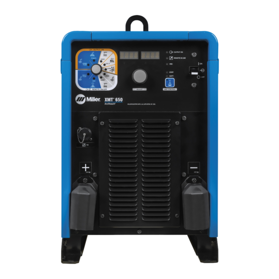
SECTION 6 – GENERAL OPERATION 6-1. Front Panel Ref. 290004-A 291147-A 4 Adjust Control 14 Arc Control Indicator For Wire Modes � Weld process operation sections de- 5 Power Switch 15 Amp Indicator scribe functionality of the identified items (See Sections thru ). 6 Arc Control Button 16 Arc Control Indicator For Stick Modes 7 Output On Indicator... -
Page 25: Mode Switch Settings
6-2. Mode Switch Settings Weld Terminal Polarity Switch Output Remote Process Panel Adjust Configura- Position Control Adjust Electrode Work tion GMAW/FCAW No Remote Output On Volts DCEP Positive Negative Adjust FCAW-S (+) No Remote Output On Volts DCEP Positive Negative No-Gas Adjust FCAW-S (-) -
Page 26: Section 7 - Gmaw/Fcaw Operation
SECTION 7 – GMAW/FCAW OPERATION 7-1. Typical Connection For Voltage-Sensing Feeder GMAW/FCAW Process Ref. 291436-A 6 Gun Use of shielding gas is dependant on Wire Turn power before making Type. connections. 7 Gun Trigger Receptacle � 1 Positive (+) Weld Output Terminal The connection diagram illustrates 8 Wire Feeder DCEP (reverse polarity) suitable for all... -
Page 27: Gmaw/Fcaw - (Gas) Or Fcaw-S (No Gas) Output-On Welding Modes
7-2. GMAW/FCAW - (Gas) Or FCAW-S (No Gas) Output-On Welding Modes Ref. 290004-A Arc Control Weld terminals are energized at all � If associated to an ArcReach feeder times in GMAW/FCAW (Gas) and with Cable Length Compensation the Pressing the Arc Control button allows ad- FCAW-S (No Gas) Output On weld- voltage display on the power source justment of Arc Control settings. -
Page 28: Section 8 - Smaw/Cac-A Operation
SECTION 8 – SMAW/CAC-A OPERATION 8-1. Typical Connection For SMAW And CAC-A Process 291152-A 3 Positive (+) Weld Output Terminal 6 Negative (-) Weld Output Terminal Turn power before making connections. 4 Remote 14 Receptacle 7 Workpiece 1 Electrode Holder (Carbon Arc) Connect desired remote control to remote 14 receptacle as required. -
Page 29: Smaw-Stick Output On Welding Mode
8-2. SMAW—Stick Output On Welding Mode Ref. 290004-A Pressing the Arc Control button allows ad- Weld terminals are energized at all � See Section 8-1 for information regard- justment of Arc Control and Programmable times in SMAW - Stick Output-On ing alternate configurations. -
Page 30: Cac-A-Gouge Output On Mode
8-3. CAC-A—Gouge Output On Mode Ref. 290004-A Weld terminals are energized at all Rotate Mode switch to CAC-A-Gouge Out- � If an ArcReach device is used for am- times in CAC-A - Gouge Output-On put On position as shown. perage adjustment, it will have full welding mode. -
Page 31: Section 9 - Maintenance And Troubleshooting
A complete Parts List is available at www.MillerWelds.com SECTION 9 – MAINTENANCE AND TROUBLESHOOTING pliers needlenose knife steelbrush nutdriver SECTION 17 MAINTENANCE & TROUBLESHOOTING chippinghammer 9-1. Routine Maintenance A complete Parts List is available at www.MillerWelds.com 17-1. Routine Maintenance SECTION 17 MAINTENANCE &... -
Page 32: Fault Code Diagnostics
9-3. Fault Code Diagnostics HELP TEMP Right Display Left Display Toggles between the identity and Displays a number to specify fault to aid in to indicate a fault. troubleshooting. HELP Unit Display Toggles Message Description HELP IN HELP 1 XX Indicates a malfunction in the primary power circuit. -
Page 33: Troubleshooting
9-4. Troubleshooting Trouble Remedy No weld output; unit completely Place line disconnect switch in On position (see Section 5-8). inoperative. Check and replace line fuse(s), if necessary, or reset circuit breaker (see Section 5-8). Check for proper input power connections (see Section 5-8). No weld output;... -
Page 34: Section 10 - Electrical Diagrams
SECTION 10 – ELECTRICAL DIAGRAMS Figure 10-1. Circuit Diagram OM-291052 Page 31... - Page 35 Ref. 290890-A OM-291052 Page 32...
- Page 36 Notes...
- Page 37 Notes...
- Page 38 Notes...
- Page 39 Effective January 1, 2022 (Equipment with a serial number preface of NC or newer) This limited warranty supersedes all previous Miller warranties and is exclusive with no other guarantees or war- ranties expressed or implied. � Field Options (NOTE: Field options are cov-...
- Page 40 Appleton, WI 54914 USA tact your distributor and/or equipment manu- facturer’s Transportation Department. International Headquarters–USA USA Phone: 920-735-4505 USA & Canada FAX: 920-735-4134 International FAX: 920-735-4125 For International Locations Visit www.MillerWelds.com ORIGINAL INSTRUCTIONS – PRINTED IN USA © Miller Electric Mfg. LLC 2022-04...
Need help?
Do you have a question about the XMT 650 and is the answer not in the manual?
Questions and answers