Table of Contents
Troubleshooting

Related Manuals for Miller XMT350 CC/CV Auto-Line CE


Summary of Contents for Miller XMT350 CC/CV Auto-Line CE
- Page 1 OM-2254 219485AH 2017−03 Processes Multiprocess Welding Description Arc Welding Power Source XMT 350 CC/CV Auto-Line ™ File: MULTIPROCESS For product information, Owner’s Manual translations, and more, visit www.MillerWelds.com...
- Page 2 We know you don’t have time to do it any other way. That’s why when Niels Miller first started building arc welders in 1929, he made sure his products offered long-lasting value and superior quality.
-
Page 3: Table Of Contents
TABLE OF CONTENTS SECTION 1 − SAFETY PRECAUTIONS - READ BEFORE USING ....... . . 1-1. - Page 4 TABLE OF CONTENTS SECTION 9 − SMAW/CAC-A OPERATION ........... . . 9-1.
-
Page 5: Declaration Of Conformity
DECLARATION OF CONFORMITY for European Community (CE marked) products. MILLER Electric Mfg. Co., 1635 Spencer Street, Appleton, WI 54914 U.S.A. declares that the product(s) identified in this declaration conform to the essential requirements and provisions of the stated Council Directive(s) and Standard(s). - Page 6 EMF DATA SHEET FOR ARC WELDING POWER SOURCE Product/Apparatus Identification Product Stock Number XMT 350 MPA 230-460 AUTO-LINE W/AUX PWR,CE 907366002 XMT 350 MPA 230-460 AUTO-LINE W/AUX PWR,TWECO, CE 907366004 XMT 350 CC/CV 230-460 AUTO-LINE W/AUX POWER, CE 907161012 INVISION 352 MPA 230-460 AUTOLINE W/AUX POWER & CE 907431002 ALUMAPOWER 350 MPA 230-460 AUTO-LINE W/AUX PWR(CE) 907420003...
-
Page 7: Section 1 − Safety Precautions - Read Before Using
SECTION 1 − SAFETY PRECAUTIONS - READ BEFORE USING som 2015−09 Protect yourself and others from injury — read, follow, and save these important safety precautions and operating instructions. 1-1. Symbol Usage DANGER! − Indicates a hazardous situation which, if Indicates special instructions. - Page 8 D Remove stick electrode from holder or cut off welding wire at FUMES AND GASES can be hazardous. contact tip when not in use. D Wear body protection made from durable, flame−resistant material Welding produces fumes and gases. Breathing (leather, heavy cotton, wool). Body protection includes oil-free these fumes and gases can be hazardous to your clothing such as leather gloves, heavy shirt, cuffless trousers, high health.
-
Page 9: Additional Symbols For Installation, Operation, And Maintenance
1-3. Additional Symbols For Installation, Operation, And Maintenance FIRE OR EXPLOSION hazard. MOVING PARTS can injure. D Do not install or place unit on, over, or near D Keep away from moving parts such as fans. combustible surfaces. D Keep all doors, panels, covers, and guards D Do not install unit near flammables. -
Page 10: California Proposition 65 Warnings
1-4. California Proposition 65 Warnings Welding or cutting equipment produces fumes or gases This product contains chemicals, including lead, known to which contain chemicals known to the State of California to the state of California to cause cancer, birth defects, or other cause birth defects and, in some cases, cancer. -
Page 11: Section 2 − Consignes De Sécurité − Lire Avant Utilisation
SECTION 2 − CONSIGNES DE SÉCURITÉ − LIRE AVANT UTILISATION fre_som_2015−09 Pour écarter les risques de blessure pour vous−même et pour autrui — lire, appliquer et ranger en lieu sûr ces consignes relatives aux précautions de sécurité et au mode opératoire. 2-1. - Page 12 chauffement ou un incendie. Avant de commencer le soudage, vérifier LES PIÈCES CHAUDES peuvent et s’assurer que l’endroit ne présente pas de danger. provoquer des brûlures. D Déplacer toutes les substances inflammables à une distance de D Ne pas toucher à mains nues les parties chaudes. 10,7 m de l’arc de soudage.
-
Page 13: Dangers Supplémentaires En Relation Avec L'installation, Le Fonctionnement Et La Maintenance
D Tenir les bouteilles éloignées des circuits de soudage ou autres LE BRUIT peut endommager l’ouïe. circuits électriques. D Ne jamais placer une torche de soudage sur une bouteille à gaz. Le bruit des processus et des équipements peut affecter l’ouïe. D Une électrode de soudage ne doit jamais entrer en contact avec D Porter des protections approuvées pour les une bouteille. -
Page 14: Proposition Californienne 65 Avertissements
RAYONNEMENT HAUTE LE SOUDAGE À L’ARC risque de FRÉQUENCE (H.F.) risque provoquer des interférences. provoquer des interférences. D L’énergie électromagnétique risque D Le rayonnement haute fréquence (H.F.) peut provoquer des interférences pour l’équipement provoquer des interférences avec les équi- électronique sensible tel que les ordinateurs et l’équipement commandé... -
Page 15: Section 3 − Definitions
A complete Parts List is available at www.MillerWelds.com SECTION 3 − DEFINITIONS 3-1. Additional Safety Symbols And Definitions Some symbols are found only on CE products. Warning! Watch Out! There are possible hazards as shown by the symbols. Safe1 2012−05 Do not discard product (where applicable) with general waste. - Page 16 A complete Parts List is available at www.MillerWelds.com Do not weld on drums or any closed containers. Safe16 2012−05 Do not remove or paint over (cover) the label. Safe20 2012−05 Disconnect input plug or power before working on machine. Safe30 2012−05 Flying pieces of parts can cause injury.
-
Page 17: Miscellaneous Symbols And Definitions
A complete Parts List is available at www.MillerWelds.com Hazardous voltage remains on input capacitors after power is turned off. Do not touch fully charged capacitors. Always wait 60 seconds after power is turned off before working on unit, OR check input ca- pacitor voltage, and be sure it is near 0 before touching any parts. -
Page 18: Section 4 − Specifications
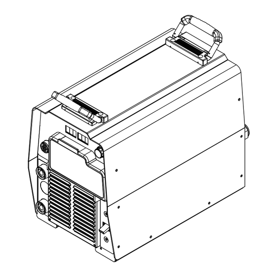
A complete Parts List is available at www.MillerWelds.com SECTION 4 − SPECIFICATIONS 4-1. Serial Number And Rating Label Location The serial number and rating information for this product is located on the rear. Use rating label to determine input power requirements and/or rated output. - Page 19 A complete Parts List is available at www.MillerWelds.com C. Information On Electromagnetic Compatibility (EMC) This Class A equipment is not intended for use in residential locations where the electrical power is provided by the public low− voltage supply system. There can be potential difficulties in ensuring electromagnetic compatibility in those locations, due to con- ducted as well as radiated disturbances.
-
Page 20: Duty Cycle And Overheating
A complete Parts List is available at www.MillerWelds.com 4-5. Duty Cycle And Overheating Duty Cycle is percentage of 10 min- utes that unit can weld at rated load without overheating. If unit overheats, output stops, a Help message is displayed and cooling fan runs. -
Page 21: Volt-Ampere Curves
A complete Parts List is available at www.MillerWelds.com 4-6. Volt-Ampere Curves Volt-ampere curves show minimum A. CC Mode and maximum voltage and amper- age output capabilities of welding power source. Curves of other set- tings fall between curves shown. SMAW GTAW SMAW GTAW... -
Page 22: Section 5 − Installation
A complete Parts List is available at www.MillerWelds.com SECTION 5 − INSTALLATION 5-1. Selecting A Location Movement Do not move or operate unit where it could tip. Location And Airflow Special installation may be required where gasoline or volatile liquids are present − see NEC Article 511 or CEC Section 20. -
Page 23: Selecting Cable Sizes
**Weld cable size (AWG) is based on either a 4 volts or less drop or a current density of at least 300 circular mils per ampere. ( ) = mm for metric use ***For distances longer than those shown in this guide, call a factory applications rep. at 920-735-4505 (Miller) or 1-800-332-3281 (Hobart). Ref. S-0007-L 2015−02 5-3. Weld Output Terminals Turn off power before connecting to weld output terminals. -
Page 24: Remote 14 Receptacle Information
A complete Parts List is available at www.MillerWelds.com 5-4. Remote 14 Receptacle Information Socket* Socket Information 24 volts AC. Protected by supplementary protect- or CB2. 24 VOLTS AC Contact closure to A completes 24 volts AC C L N contactor control circuit. Output to remote control;... -
Page 25: Optional Gas Valve Operation And Shielding Gas Connection
A complete Parts List is available at www.MillerWelds.com 5-6. Optional Gas Valve Operation And Shielding Gas Connection Obtain gas cylinder and chain to running gear, wall, or other station- ary support so cylinder cannot fall and break off valve. Cylinder Regulator/Flowmeter Install so face is vertical. -
Page 26: Electrical Service Guide
A complete Parts List is available at www.MillerWelds.com 5-7. Electrical Service Guide Elec Serv 2017-01 NOTICE − INCORRECT INPUT POWER can damage this welding power source. This welding power source requires a CONTINUOUS supply of input power at rated frequency(+10%) and voltage (+10%). Phase to ground voltage shall not exceed +10% of rated input voltage. Do not use a genera- tor with automatic idle device (that idles engine when no load is sensed) to supply input power to this welding power source. - Page 27 A complete Parts List is available at www.MillerWelds.com Notes OM-2254 Page 21...
-
Page 28: Connecting 3-Phase Input Power
A complete Parts List is available at www.MillerWelds.com 5-8. Connecting 3-Phase Input Power = GND/PE Earth Ground Tools Needed: Input2 2012−05 − Ref. 803 766-C / Ref. 802 136-A / Ref. 803 879-B OM-2254 Page 22... - Page 29 A complete Parts List is available at www.MillerWelds.com 5-8. Connecting 3-Phase Input Power (Continued) voltage available at site. This unit can be con- Input Conductors (L1, L2 And L3) Installation must meet all National and nected to any input power between 208 and Local Codes −...
-
Page 30: Section 6 − Operation
A complete Parts List is available at www.MillerWelds.com SECTION 6 − OPERATION 6-1. Front Panel Controls 803 692-C /242 020-A values after arc initiation and remains dis- set towards maximum, “wetness” (puddle Weld process operation sections de- played for approximately three seconds fluidity) increases. -
Page 31: Mode Switch Settings
A complete Parts List is available at www.MillerWelds.com 6-2. Mode Switch Settings Switch Position Process Output Control Panel Adjust Remote Adjust Scratch Start TIG GTAW Electrode Hot Amps % Panel Amps Lift-Arc TIG GTAW Electrode Hot Amps % Panel Amps GTAW Remote 14 Amps... -
Page 32: Section 7 − Gtaw Operation
A complete Parts List is available at www.MillerWelds.com SECTION 7 − GTAW OPERATION 7-1. Typical Connection For GTAW Process 264 339-A Remote 14 Receptacle Gas Out Connection (Optional) Turn off power before making con- nections. Connect desired remote control to Remote Negative (−) Weld Output Terminal 14 receptacle if required. -
Page 33: Scratch Start Tig Welding Mode - Gtaw Process
A complete Parts List is available at www.MillerWelds.com 7-2. Scratch Start TIG Welding Mode - GTAW Process 8 4.5 242 020-A Setup Operation Weld terminals are energized at all times in Scratch Start TIG welding For typical system connections refer to The Adjust Control is used to set desired mode. -
Page 34: Lift-Arc Tig Welding Mode - Gtaw Process
A complete Parts List is available at www.MillerWelds.com 7-3. Lift-Arc TIG Welding Mode - GTAW Process 1 3. 5 242 020-A 1 − 2 “Touch” Seconds Do NOT Strike Like A Match! Rotate Mode Switch to LIFT-ARC TIG posi- welding, momentarily depress output Weld terminals are energized at all tion as shown. -
Page 35: Tig Welding Mode - Gtaw Process
A complete Parts List is available at www.MillerWelds.com 7-4. TIG Welding Mode - GTAW Process 242 020-A Setup Operation Weld terminals energized through the remote control in TIG For typical system connections refer to The Adjust Control is used to set desired welding mode. -
Page 36: Section 8 − Gmaw/Fcaw Operation
A complete Parts List is available at www.MillerWelds.com SECTION 8 − GMAW/FCAW OPERATION 8-1. Typical Connection For Remote Control Feeder GMAW/FCAW Process 264 343-A Workpiece Use of shielding gas is dependant on Wire Turn off power before making Type. connections. Remote 14-Receptacle The connection diagram illustrates Wire Feeder... -
Page 37: Mig Welding Mode - Gmaw/Fcaw Process
A complete Parts List is available at www.MillerWelds.com 8-2. MIG Welding Mode - GMAW/FCAW Process 2 5.0 242 020-A Rotate Mode Switch to MIG position as has a voltage control. This voltage con- Weld terminals energized shown. trol will override the Adjust Control of through the remote control in MIG preset voltage on the welding power welding mode. -
Page 38: Typical Connection For Remote Control Feeder Gmaw-P Process
A complete Parts List is available at www.MillerWelds.com 8-3. Typical Connection For Remote Control Feeder GMAW-P Process 264 347-A Workpiece Turn off power before making The connection diagram illustrates connections. DCEP (reverse polarity) suitable for all Optima - External Pulsing Device Wire Feeder wires except self-shielded FCAW. -
Page 39: Pulsed Mig Welding Mode - Gmaw-P Process
A complete Parts List is available at www.MillerWelds.com 8-4. Pulsed MIG Welding Mode - GMAW-P Process P P.P 242 020-A Adjust Control Left and Right Display will show PPP PPP. Weld terminals energized through the remote control in Setup Operation Pulsed MIG welding mode. -
Page 40: Typical Connection For Voltage-Sensing Feeder Gmaw/Fcaw Process
A complete Parts List is available at www.MillerWelds.com 8-5. Typical Connection For Voltage-Sensing Feeder GMAW/FCAW Process 264 348-A Use of shielding gas is dependant on Wire Turn off power before making con- Type. nections. Gun Trigger Receptacle Positive (+) Weld Output Terminal The connection diagram illustrates Negative (−) Weld Output Terminal Wire Feeder... -
Page 41: V-Sense Feeder Welding Mode - Gmaw/Fcaw Process
A complete Parts List is available at www.MillerWelds.com 8-6. V-Sense Feeder Welding Mode - GMAW/FCAW Process 2 5.0 242 020-A to Section 8-5. Weld terminals are energized at all The Left Display toggling momentarily times in V-Sense Feeder welding pauses while the preset voltage is ad- Rotate Mode Switch to V-SENSE FEEDER mode. -
Page 42: Section 9 − Smaw/Cac-A Operation
A complete Parts List is available at www.MillerWelds.com SECTION 9 − SMAW/CAC-A OPERATION 9-1. Typical Connection For SMAW And CAC-A Process 264 349-A cutting torch to to positive weld output ter- Connect desired remote control to remote Turn off power before making con- minal. -
Page 43: Cc Welding Mode - Smaw/Cac-A Process
A complete Parts List is available at www.MillerWelds.com 9-2. CC Welding Mode - SMAW/CAC-A Process 242 020-A Operation Arc Control (Dig) Weld terminals energized The Adjust Control is used to set desired through the remote control in CC Rotate Arc Control to select desired dig set- preset amperage. -
Page 44: Stick Welding Mode - Smaw/Cac-A Process
A complete Parts List is available at www.MillerWelds.com 9-3. Stick Welding Mode - SMAW/CAC-A Process 8 4.5 242 020-A The open circuit voltage is shown in the Left Arc Control (Dig) Weld terminals are energized at all Display and the preset amperage is shown times in Stick welding mode. -
Page 45: Optional Low Open Circuit Voltage (Ocv) Welding Modes
A complete Parts List is available at www.MillerWelds.com 9-4. Optional Low Open Circuit Voltage (OCV) Welding Modes Low OCV Operation The unit can be optionally configured for low open circuit voltage (OCV) operation in Stick and Scratch Start TIG modes. When the unit is config- ured for low OCV operation only a low sensing voltage (approximately 15 VDC) is present between the electrode and the workpiece prior to the electrode touching the workpiece. -
Page 46: Section 10 − Maintenance & Troubleshooting
A complete Parts List is available at www.MillerWelds.com SECTION 10 − MAINTENANCE & TROUBLESHOOTING 10-1. Routine Maintenance Disconnect power Maintain more often during before maintaining. severe conditions. n = Check Z = Change ~ = Clean l = Replace Every Replace Damaged Replace Cracked... -
Page 47: Help Displays
A complete Parts List is available at www.MillerWelds.com 10-3. Help Displays All directions are in reference to the front of the unit. All circuitry referred to is lo- cated inside the unit. Help 1 Display HELP Indicates a malfunction in the primary power circuit. -
Page 48: Troubleshooting
A complete Parts List is available at www.MillerWelds.com 10-4. Troubleshooting Trouble Remedy No weld output; unit completely inop- Place line disconnect switch in On position (see Section 5-8). erative. Check and replace line fuse(s), if necessary, or reset circuit breaker (see Section 5-8). Check for proper input power connections (see Section 5-8). - Page 49 A complete Parts List is available at www.MillerWelds.com Notes OM-2254 Page 43...
-
Page 50: Section 11 − Electrical Diagram
SECTION 11 − ELECTRICAL DIAGRAM Figure 11-1. Circuit Diagram OM-2254 Page 44... - Page 51 271 739-A OM-2254 Page 45...
- Page 52 Notes...
- Page 53 Notes Start Your Professional Over 80,000 trained 400 Trade Square East, Troy, Ohio 45373 Welding Career Now! since 1930! 1-800-332-9448 www.welding.org...
- Page 54 Notes...
- Page 55 Effective January 1, 2017 (Equipment with a serial number preface of MH or newer) This limited warranty supersedes all previous Miller warranties and is exclusive with no other guarantees or warranties expressed or implied. Warranty Questions? LIMITED WARRANTY − Subject to the terms and conditions below, 6 Months —...
- Page 56 Contact the Delivering Carrier to: File a claim for loss or damage during shipment. For assistance in filing or settling claims, contact your distributor and/or equipment manufacturer’s Transportation Department. © ORIGINAL INSTRUCTIONS − PRINTED IN USA 2017 Miller Electric Mfg. Co. 2017−01...
Need help?
Do you have a question about the XMT350 CC/CV Auto-Line CE and is the answer not in the manual?
Questions and answers