Advertisement
Advertisement
Table of Contents

Related Manuals for Inter-m P-2000


Summary of Contents for Inter-m P-2000
- Page 1 OPERATING MANUAL PROFESSIONAL SOUND REINFORCED AMPLIFIER P-2000/3200...
-
Page 2: Unpacking And Installation
UNPACKING AND INSTALLATION Although it is neither complicated to install nor difficult to operate your power Amplifier, a few minutes of your time is required to read this manual for a properly wired installation and becoming familiar with its many features and how to use them. - Page 3 FEATURES • HIGH POWER AND HIGH FIDELITY The designed sound level can be obtained without using the full power output. To insure stability and fidelity against various protection circuitry is provided. • DUAL POWER P series amplifier has to be separated power. If one channel is break down, this amplifier can be perform well by another channel.
-
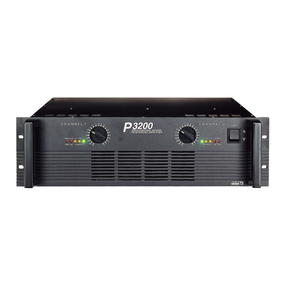
Page 4: Front Panel Controls
FRONT PANEL CONTROLS POWER 3200 CHANNEL1 CHANNEL 2 PROFESSIONAL SOUND REINFORCED AMPLIFIER PROT CLIP 15 CLIP PROT TEMP POWER POWER TEMP 1. POWER SWITCH The power switch is used to turn on and off the AC main power. 2. POWER INDICATORS Power indicating LED is driven by power switch, and the LED illuminates when the amplifier is powered ON. -
Page 5: Rear Panel Controls
REAR PANEL CONTROLS ( + ) CHANNEL 1 CHANNEL 2 BRIDGED MONO CAUTION; TO REDUCE THE RISK OF ELECTRIC SHOCK, DO NOT REMOVE COVER. NO USER SERVICEABLE PARTS INSIDE. REFER SERVICING TO QUALIFIED SERVICE PERSONNEL. AVIS; RISQUE DE CHOC ELECTRIOUE NE PAS OUVRIR. MADE IN KOREA PUSH PUSH... - Page 6 4. OUTPUT CONNECTORS Output terminals are dual five-way binding posts and speaker connectors. * When speakers are connected amplifier, please make sure correct connection of each pin, and refer speaker pin number. CHANNEL 2 ( + ) CHANNEL 1 BRIDGED MONO PIN 1+ POS PIN 1-GND PIN 1+ POS...
-
Page 7: Stereo Mode
STEREO MODE AND BRIDGE MODE • STEREO MODE In this mode, channels A and B operate independently (typical stereo amplifier). Channel A input signal feeds channel A power amp, and channel B input signal feeds channel B power amp. In this mode, the minimum speaker impedance per channel is 4Ω. -
Page 8: Speaker Cable
CAUTION FOR SPEAKER CONNECTION AND INSTALLATION 1. Turn off the POWER switch. 2. After removing approx. 10mm of insulation from the ends of the speaker cables, pass the bare ends of the speaker wires through the holes in the corresponding speaker terminals and tighten the terminals to securely clamp the wires. -
Page 9: Specifications
SPECIFICATIONS ELECTRICAL • Rated Output (1KHz, 1% THD) P3200 (per channel) ........................750W (per channel) ........................1200W (per channel) ........................1400W (bridged mono) ........................2400W (bridged mono) ........................2800W P2000 (per channel) ........................500W (per channel) ........................750W (per channel) ........................1000W (bridged mono) ........................ - Page 10 MADE IN KOREA...
Need help?
Do you have a question about the P-2000 and is the answer not in the manual?
Questions and answers