Table of Contents
Advertisement
Advertisement
Table of Contents

Subscribe to Our Youtube Channel
Related Manuals for Inter-m PAM-510


Summary of Contents for Inter-m PAM-510
-
Page 1: Operation Manual
Operation Manual ATT. Zone Amplifier PAM-510/520... -
Page 2: Table Of Contents
ATT. ZONE AMPLIFIER Contents Contents Welcome Warning............................1 Unpacking ............................2 Installation Environment............................2 Important Safety Instructions......................2 Features ............................3 Accessories.............................3 Operation ............................3 Front Panel ............................4 Rear Panel ............................6 Connecting Speakers ........................9 Application of the Antenna ......................10 Applications ..........................11 Block Diagram ..........................12 Specifications ..........................13 Service Procedures............................14 Schematic .............................14... -
Page 3: Warning
A personal welcome to you from the management and employees of Inter-M All of the co-workers here at Inter-M are dedicated to providing excellent products with inherently good value, and we are delighted you have purchased one of our products. -
Page 4: Unpacking
ATT. ZONE AMPLIFIER Unpacking Although your PAM-510 or PAM-520 is neither complicated nor difficult to operate, we recommend you take a few minutes to read this brief manual and familiarize yourself with the important information regarding product features, setup and operation. -
Page 5: Features
Keep volume levels turned down before switching on. NOTE: The system’s operation is delayed by approximately three seconds after pressing the power switch. This is due to the built-in protection circuitry, designed to protect the speakers and other system components. PAM-510/520... -
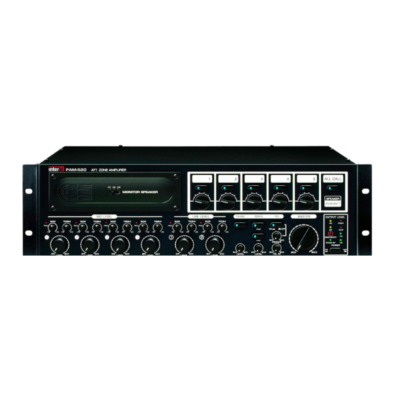
Page 6: Front Panel
4. CHANNEL VOLUME Controls the individual volume levels of Channels. 5. CHIME Pressing this button will activate the one shot chime. Depending upon the volume adjustment the level of signal and mute level are varied. PAM-510/520... - Page 7 These three LEDs indicate the amplifier s output status. The -40dB LED indicates the presence of audio signal at the amplifier’s output. The -10dB LED indicates output at nominal operating range. The red CLIP LED indicates an excessive output level. Do not operate the unit with the CLIP LED continuously on (illuminated). PAM-510/520...
-
Page 8: Rear Panel
SPK 1~5 Terminal (LOW IMPEDANCE) (HIGH IMPEDANCE) Model Name EC & Associated : 100V/400Ω (25W MAX) PAM-510 22V/4Ω (120W) USA/CANADA & Associated : 70V/196Ω (25W MAX) EC & Associated :100V/200Ω (50W MAX) PAM-520 31V/4Ω (240W) USA/CANADA & Associated : 70V/98Ω (50W MAX) 2. - Page 9 These terminals are provided for the connection of backup battery. Connect a 24VDC 50A battery source to these terminals. Make certain the red terminal is connected to the battery’s positive (+) side, and the black terminal to the battery’s negative (–) side. 12. REMOTE POWER You can turn on/off amplifier by remote control. PAM-510/520...
- Page 10 This is a special connector which will accept either a 3-conductor XLR or a 3-conductor 1/4” jack. These inputs are suitable to receive signal from microphones level devices. MIC JACK (XLR JACK) LINE JACK (TRS PHONE JACK) Pin 1: GROUND Sleeve: GROUND Pin 2: HOT(+) Tip: HOT(+) Pin 3: COLD(–) Ring: COLD(–) PAM-510/520...
-
Page 11: Connecting Speakers
- CONNECTING HIGH-VOLTAGE DISTRIBUTED SPEAKER SYSTEMS When connecting a high-impedance(70V/100V) speaker system in parallel, you can connect speakers with a total rated input of up to 25W (PAM-510) or 50W (PAM-520). Total rated input of up to 25W (PAM-510) or 50W (PAM-520) Output 4Ω... -
Page 12: Application Of The Antenna
Install the vinyl-coated cable to an outdoor place if the AM reception is not good enough. - AM LOOP ANTENNA Connecting the feeder of the loop antenna of the terminal of 300Ω. Listening to the broadcasting, fix it after deciding the location and the direction so that the receipt condition may be optimum. PAM-510/520... -
Page 13: Applications
ATT. ZONE AMPLIFIER Applications Applications PAM-510/520... -
Page 14: Block Diagram
ATT. ZONE AMPLIFIER Block Diagram Block Diagram PAM-510/520... -
Page 15: Specifications
Operating Temperature –10°C~40°C Power Source 100–120VAC or 220–240VAC; 50/60Hz, 24VDC Power Consumption (1/8 POWER) 180W 320W Weight 17kg/37.6lb 19kg/42lb Dimensions 482(W) x 132(H) x 398(D)mm 19(W) x 5.2(H) x 15.7(D)in * Specifications and design subject to change without notice. PAM-510/520... -
Page 16: Service
To obtain specific warranty information and available service locations contact Inter-M directly(in Korea or the USA) or the authorized Inter-M Distributor for your specific country or region. - Page 17 Inter-M, Ltd. (Korea) began operations in 1983. Since then, Inter-M has grown to become one of the largest manufacturers of professional audio and commercial sound electronics equipment in the world. Inter-M has gained worldwide recognition for its own branded products, as well as private label manufacturing of electronics sold under other names (OEM).
Need help?
Do you have a question about the PAM-510 and is the answer not in the manual?
Questions and answers