Subscribe to Our Youtube Channel
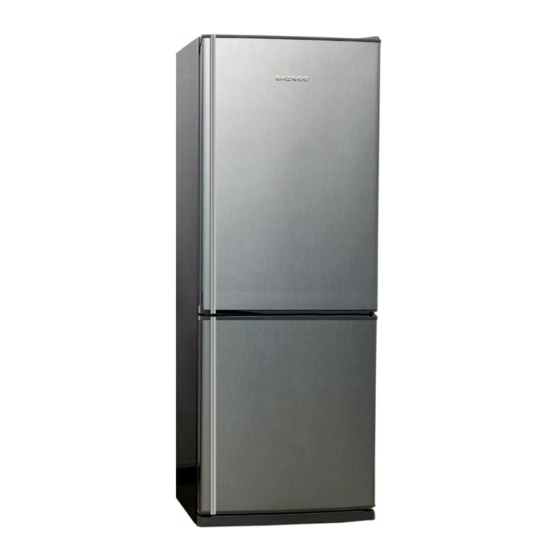
Summary of Contents for Daewoo ERF-368MBW
- Page 1 Service manual Model name: ERF-368MBW, ERF-368MBI, ERF-368MBB, ERF-388MBW, ERF-388MBI, ERF-388MBB, ERF-387MH_E, ERF-387MS_E...
-
Page 2: Table Of Contents
. CONTENTS 1. SPECIFICATIONS 2. EXTERNAL DRAWINGS 3. MACHINE ROOM VIEW 4. REFRIGERANT CYCLE 5. WIRING DIAGRAM 6. COMPONENTS DISASSEMBLY PICTURES 7. DOOR POSITION CHANGE PROCESS 8. EXPLODE DRAWING 9. PARTS LIST... -
Page 3: Specifications
1. SPECIFICATIONS Technical name 368/7 3388/7 398/7 418/7 Division MECHANIC TYPE Refrigerant type R-134A Refrigerant Q´ty 100 grs Blowing agent C-PENTANE Cooling system Fan cooling system Defrost system Automatic start & Automatic stop system Compressor KPC CBE-140L5Z Rated voltage AC220~240V / 50Hz Rated input (W) Lamp rated input (W) Freezer... -
Page 4: External Drawings
2. EXTERNAL DRAWINGS MODEL 1722 862.5 621.5 1765 ER F-3 68/7 1098 993.5 621.5 ER F-398/7 1896 1853 638.5 ER F- 3 88/7 710.5 862.5 1854 1811 1985 1942 1098 993.5 710.5 ER F-4 18/7 32.5 59 5. 2... -
Page 5: Machine Room View
3. MACHINE ROOM VIEW SCREW MACHINE... -
Page 6: Refrigerant Cycle
4. REFRIGERANT CYCLE CAPILLARY TUBE... -
Page 7: Wiring Diagram
5. WIRING DIAGRAM... -
Page 8: Components Disassembly Pictures
6. COMPONENTS DISASSEMBLY PICTURES - SWITCH DOOR - Force switch door to the left side and input a thin driver in the rigth part as picture shows. After this operation, lift switch up. * Remark: Input driver carefully in order to lift up easily and avoid paint damages and scratches. - Page 9 - MULTI DUCT - Unscrew all fixed screws. - Remove insulator multi-duct. - Unscrew defrost timer and thermostat. - Take out temperature control knob by a minus driver carefully.
- Page 10 - LOUVERS: - Unscrew the two fixing screw for diassembly louver A and B TO DISASSEMBLE IT IS NECESSARY A STAR DRIVER WITH A MINIMAL LENGHT OF 10 CM - Disconnect fan motor housing - Unscrew the fixing screw in order to disassemble Louver A.
- Page 11 L POSITION - When louvers are disassembled is very important check Knob F louver position. Default position is M L POSITION H POSITION -CHANGE DOOR OPEN SIDE - Unscrew cover T hinge Follow next sheets instructions to change door open side...
-
Page 12: Door Position Change Process
7. DOOR POSITION CHANGE PROCESS STEP 1 : Remove door Follow to remove 1. Remove“ COVER HINGE” and “ HINGE T” 2. Remove“ R” door. 3. Remove “ HINGE M” 4. Remove“ F” door 5. Remove“COVER BRACKET” 6. Remove“ HINGE U” STEP 2 : Change door handle 7. - Page 13 door open side STEP 3 : Change the position of door 11. Attach the“ HINGE U” on the left. 12. Attach the“ F DOOR” 13. Reverse the position of “ HINGE M” and “ CAP SCREW HOLE” 1. Attach the“ R DOOR” 15.
-
Page 15: Part List
DMS1467460 COVER DOOR CAP *R BAR HANDLE (NOBLE GREY) NOBLE GREY DMS1467470 COVER DOOR CAP *R BAR HANDLE (BLACK) BLACK 3013595400 EMBLEM DAEWOO '04 (CHROME) 3012306600 GASKET R DR 36./38. WHITE DMS2306630 GASKET R DR 36./38. GRAY COLOR DARK GREY DMS0085580 R DOOR BAR (SNOW WHITE) 384NBW(BAR H.D2) -
Page 16: Explode Drawing
MOTOR FAN AS SHAFT 3,17 A GRADE 230V/50HZ 3018918900 LOUVER F B 366/396 3018919000 LOUVER FB 386/416 3011801410 FAN GRADO A 3011200520 FIXTURE FAN RING (SPRING) DAEWOO 2005 3018918700 LOUVER F A 366/396 3018918800 LOUVER FA 386/416 3018920700 LOUVER F C 3013410700... - Page 17 DAEWOO ELECTRONICS MANUFACTURING ESPAÑA S.A Polígono industrial de Júndiz C/Zurrupitieta 27, 01015 Vitoria, Spain Tel: 00 34 945292292 Fax:00 34 945290965...


Need help?
Do you have a question about the ERF-368MBW and is the answer not in the manual?
Questions and answers