Table of Contents
Advertisement
Advertisement
Table of Contents

Related Manuals for Daewoo ERF-384


Summary of Contents for Daewoo ERF-384
- Page 1 Manual de servicio Refrigeradores ERF-384 ESPAÑOL Modelo:...
-
Page 2: Table Of Contents
C O N T E N T S 1. Specifications ....................2. -
Page 4: Specifications
1. SPECIFICATIONS Specification 1.1 Product specification Model name ERF-334 ERF-364 ERF-384 ERF-394 ERF-414 Division Refrigerant type R-134A Refrigerant Q´ty 0.09Kg 0.1Kg 0.1Kg 0.1Kg 0.1Kg 0.1Kg 0.1Kg 0.1Kg 0.1Kg Blowing agent C-PENTANE Cooling system Fan cool system Defrost system Automatic start & Automatic stop system... -
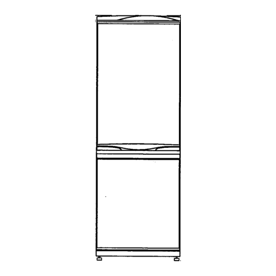
Page 5: External Drawings
2. EXTERNAL DRAWINGS 1. ERF-334M 2. ERF-364A(M), 384A(M), 394A(M), 414A(M), 367A(M), 387A(M), 397A(M), 417A(M) -
Page 6: Wiring Diagrams
3. WIRING DIAGRAMS 1. ERF-334M 2. ERF-367A, 387A, 397A, 417A... - Page 7 3. ERF-364A, 384A, 394A, 414A 4. ERF-364M, 384M, 394M, 414M...
-
Page 8: Air Flow Diagram
4. AIR FLOW DIAGRAM Fresh food preserving case (Chilled case) Used for storing fish or meat Case vegetable For storing fruits or vegetables Air circulation in the freezer compartment Cold air flow comes out from the front hole and comes into the lower hole in louver * Standard Model... -
Page 9: Refrigerant Cycle Diagram
5. REFRIGERANT CYCLE DIAGRAM COMPRESSOR PIPE CONN. B HOT PIPE WI-CON PIPE DRYER SUCTION PIPE CONN. SUCTION PIPE EVAPORATOR CAPILLARY TUBE... -
Page 10: Machine Room View And Part List
6. MACHINE ROOM VIEW AND PART LIST 14-11 14-10 DETAIL "X" DETAIL "X" 14-9 14-4 14-1 14-8 14-5 14-2 14-3 Nº PART NAME Nº PART NAME Nº PART NAME PIPE HOT BOX RELAY AS CAP DRAINER ABSORBER COMP. 14-1 BOX RELAY SCREW TAPPING COMPRESSOR 14-2... -
Page 11: Components Disassembly Pictures
7. COMPONENTS DISASSEMBLY PICTURES 1- CONTROL PANEL 1) Take out control panel by pulling it up and inserting a minus driver like picture shows, and move it left-right. 2) F-Pcb harness, and switch lamp. 3) Remove 2 upper screws to take out base control panel. - Page 12 Components disassembly pictures 4) Detach all connectors of M-Pcb and take out it. 5) Disassembly control panel: 5.1) Klasse A type: 5.1.1) Unscrew WINDOW C/ PANEL L/L 5.1.2) Take out L/L F-PCB pulling forward 5.1.3) Take out window led...
- Page 13 Components disassembly pictures 5.2) Digicom type: 5.2.1) Unscrew window C/ PANEL C/L 5.2.2) Take out WINDOW C/ PANEL C/L 5.2.3) Take out C/L F-PCB PULLING pulling formad * REMARK: Disassembly system for M type models is similar but with less components.
- Page 14 Components disassembly pictures 2- COVER MULTI-DUCT (FOR M TYPE MODELS) 1) Remove the window by pushing lower part upward and pulling forward. 2) Remove 3 fixing screws. 3) Pull forward with instant force. 4) Remove socket lamp harness and timer/thermostat harness by pressing the housing with the fingers.
- Page 15 Components disassembly pictures 5) Retirar aislamiento del multiducto 6) Desatornillar temporizador 7) Retirar temporizador de deshielo 8) Take out temperature control knob by a minus driver carefully.
- Page 16 Components disassembly pictures 9) Take out thermostat by unscrewing it. * REMARK: Disassembly system for automatic or digital models is similar but with less components. 3 SELLO MAGNETICO 1) Take out the gasket as shown. 2) Fix the new one. 4- FREEZER COMPARTMENT 1) Remove 2 fixing screws.
- Page 17 Components disassembly pictures 2) Remove louver FA (to prevent damages is better disassembly it like pictures show). 3) Remove 2 fixing screws of louver B. 4) Take out louver FB by hand.
- Page 18 Components disassembly pictures 5) Disconnect fan motor housing. 6) Take out defrost heater. 7) Disconnect housings of d-heater. 8) Disconnect Bi-metal housing and cut cable tie (FOR M TYPE ONLY)
- Page 19 Components disassembly pictures 9) Take out fuse pulling out the fuse temp fixture. 4.1 FOR REPLACE FUSE TEMP AND D-SENSOR 1) Cut black and grey wires and take out the fuse. 2) Join cut wires with the new fuse wires.
- Page 20 Components disassembly pictures 3) Cover joint point with insulated tape * REMARK: for replace D-sensor in A type models, is used the same system. 5- DOOR SWITCH ERF-334M 1) Remove the door switch out of cabinet by inserting “-“ screw driver, carefully like picture shows.
-
Page 21: Components Specifications
8. COMPONENTS SPECIFICATIONS 1. COMPRESSOR ERF-334M/364A/364M/394A/394M/384A/384M/414A/414M /367A/387A/397A/417A Part name HPL17YH-5 Part code 3956117S50 Rated voltage 220~240V / 50Hz Starting type RSCR Refrigerant R-134a 2. PTC ERF-334M/364A/364M/394A/394M/384A/384M/414A/414M ERF-367A/387A/397A/417A Part name SWITCH P RELAY PTC Part code 3817923700 3. OLP ERF-334M/364A/364M/394A/394M/384A/384M/414A/414M ERF-367A/387A/397A/417A Part name 4TM129SHBYY-53 Part code... - Page 22 Component specifications 8. SWITCH LAMP ERF-334M ERF-364A/364M/394A/394M/384A/384M/414A/414M ERF-367A/387A/397A/417A Type DSD-6 1051 Specification 250V, 0.5A 250V, 0.25A Part code 3011721300 3018111500 9. SOCKET LAMP AS ERF-334M/364A/364M/394A/394M/384A/384M/414A/414M ERF-367A/387A/397A/417A Type Specification AC 250V Part code 3017903900 10. FUSE TEMPERATURE ERF-334M/364A/364M/394A/394M/384A/384M/414A/414M ERF-367A/387A/397A/417A Type SW-105T Specification AC250V, 77ºC Part code...
- Page 23 9. EXPLODE DRAWINGS 1. ERF-334M...
- Page 24 Explode drawings...
- Page 25 10. PART LIST 1. Part list (ERF-334M type) PART NAME PART CODE MODEL DESCRIPTION REMARK SHELF R 3017823200 GPPS 394/414 COVER VEGTB CASE 3011453600 GPPS CASE VEGTB 3011163480 GPPS CASE ICING 3011163200 CASE FD 3011163140 HIPS CASE FB AS 3011168300 CASE+COVER CASE FA AS 3011164100...
- Page 26 Part List PART NAME PART CODE MODEL DESCRIPTION REMARK HARNESS EARTH 3012735200 HOUSING+RING TERMINAL PIPE CHARGE 3014418202 DUCT1-O SPECIAL WASHER 3016004700 /4.3 STAR earth:4 SWITCH P RELAY OL 3817923600 4TM129SHBYY-53 SWITCH P RELAY PTC 3817923700 33Ω REALY BOX 3810506400 NORYL CABLE CLAMP 3818200300 NORYL...
- Page 27 EXPLODE DRAWINGS 2. ERF-384M...
- Page 28 Explode drawings...
- Page 29 PART LIST 2. Part list (ERF-384M) PART NAME PART CODE MODEL DESCRIPTION REMARK SHELF R 3017823200 GPPS 394/414 COVER VEGTB CASE 3011453600 GPPS CASE VEGTB 3011163480 GPPS CASE ICING 3011163200 CASE FD 3011115940 HIPS CASE FC 3011115410 HIPS CASE FA 3011115230 HIPS PLATE SHELF GLASS...
- Page 30 Part List PART NAME PART CODE MODEL DESCRIPTION REMARK SCREW MACHINE 7051401065 PAN 4x10 BSNI HARNESS EARTH 3012735200 HOUSING+RING TERMINAL PIPE CHARGE 3014418202 DCUT1-/6xT0.6x100 SPECIAL WASHER 3016004700 /4.3 STAR earth:4 SWITCH P RELAY OL 3817923600 4TM129SHBYY-53 SWITCH P RELAY PTC 3817923700 33Ω...
- Page 31 EXPLODE DRAWINGS 3. ERF-364M, ERF-394M, ERF-414M...
- Page 32 Explode drawings...
- Page 33 PART LIST 3. Part list (ERF-364M, ERF-394M, ERF-414M Type) PART NAME PART CODE MODEL DESCRIPTION REMARK SHELF R 3017823200 GPPS 391/411 COVER CHILLED CASE 3011453400 GPPS CASE CHILD 3011163300 GPPS COVER VEGTB CASE 3011453600 GPPS CASE VEGTB 3011163480 GPPS CASE ICING 3011163200 CASE FD 3011115940...
- Page 34 Part List PART NAME PART CODE MODEL DESCRIPTION REMARK CAP DRAIN HOSE 3010919700 CASE VAPORY 3011162600 FIXTURE COMP 3012005300 SK5+ZN5-C t0.8 DRYER ASSY 3016802202 15Gr (t0.51) ABSORBER COMP 3010101700 BASE COMP 3010318600 SBHG t1.0 SPECIAL SCREW A 3016004300 M6.5xL20 CAPACITOR RUN 3016402110 SPECIAL WASHER R/C 3016006410...
- Page 35 EXPLODE DRAWINGS 4. ERF-384A...
- Page 36 Explode drawings...
- Page 37 PART LIST 4. Parts list (ERF-384A) PART NAME PART CODE MODEL DESCRIPTION REMARK SHELF R 3017823200 GPPS 394/414 COVER VEGTB CASE 3011453600 GPPS CASE VEGTB 3011163480 GPPS CASE ICING 3011163200 CASE FD 3011115940 HIPS CASE FC 3011115410 HIPS CASE FA 3011115230 HIPS PLATE SHELF GLASS...
- Page 38 Part List PART NAME PART CODE MODEL DESCRIPTION REMARK HARNESS EARTH 3012735200 HOUSING+RING TERMINAL PIPE CHARGE 3014418202 DUCT1-O SPECIAL WASHER 3016004700 /4.3 STAR earth:4 SWITCH P RELAY OL 3817923600 4TM129SHBYY-53 SWITCH P RELAY PTC 3817923700 33Ω RELAY BOX 3810506400 NORYL CABLE CLAMP 3818200300 NORYL...
- Page 39 EXPLODE DRAWINGS 5. ERF-364A, ERF-394A, ERF-414A...
- Page 40 Explode drawings...
- Page 41 PART LIST 5. Part List (ERF-364A, 394A, 414A Type) PART NAME PART CODE MODEL DESCRIPTION REMARK SHELF R 3017823200 GPPS 391/411 COVER CHILLED CASE 3011453400 CASE CHILD 3011163300 GPPS COVER VEGTB CASE 3011453600 GPPS CASE VEGTB 3011163480 GPPS CASE ICING 3011163200 CASE FD 3011115940...
- Page 42 Part List PART NAME PART CODE MODEL DESCRIPTION REMARK CASE VAPORY 3011162600 FIXTURE COMP 3012005300 SK5+ZN5-C t0.8 DRYER ASSY 3016802202 15Gr (t0.51) ABSORBER COMP 3010101700 BASE COMP 3010318600 SBHG t1.0 SPECIAL SCREW A 3016004300 M6.5xL20 CAPACITOR RUN 3016402110 4uF 400AC SPECIAL WASHER R/C 3016006410 SPECIAL NUT R/C...
- Page 43 PART LIST Part list of colour components (ERF-364A/M, ERF-384A/M, ERF-394A/M, ERF-414A/M) WHITE PART NAME PART CODE MODEL DESCRIPTION REMARK 364 394 PANEL CONTROL L/L A 3014231000 electronic PANEL CONTROL L/L M 3014231000 mechanical BASE CONTROL PANEL 3010312900 HIPS REFRIGERATOR DOOR (364) 3010057730 URT FORMING ( CO-LAMINAR ) REFRIGERATOR DOOR (384)
- Page 44 Part List INOX (DARK GREY) PART NAME PART CODE MODEL DESCRIPTION REMARK 364 394 CONTROL PANEL A 3014231010 electronic CONTROL PANEL M 3014231010 mechanical BASE CONTROL PANEL 3010312910 HIPS REFRIGERATOR DOOR (364) 3010057830 URT FORMING ( INOX ) REFRIGERATOR DOOR (384) 3010057870 URT FORMING ( INOX ) REFRIGERATOR DOOR (394-414)
- Page 45 EXPLODE DRAWINGS 6. ERF-387A...
- Page 46 Explode drawings...
- Page 47 PART LIST 6. Part list (ERF-387A) PART NAME PART CODE MODEL DESCRIPTION REMARK PLATE SHELF GLASS 3014547700 GLASS t4.0 PLATE V/CASE COVER GLASS 3014547800 GLASS t4.0 FRAME GLASS SHELF 3012202400 HIPS FRAME V/CASE COVER 3012202600 HIPS CASE VEGTB 3011163480 GPPS CASE ICING 3011163200 CASE FD...
- Page 48 Part List PART NAME PART CODE MODEL DESCRIPTION REMARK HARNESS EARTH 3012735200 HOUSING+RING TERMINAL PIPE CHARGE 3014418202 DUCT1-O SPECIAL WASHER 3016004700 /4.3 STAR earth:4 SWITCH P RELAY OL 3817923600 4TM129SHBYY-53 SWITCH P RELAY PTC 3817923700 33Ω RELAY BOX 3810506400 NORYL CABLE CLAMP 3818200300 NORYL...
- Page 49 EXPLODE DRAWINGS 7. ERF-367A, ERF-397A, ERF-417A...
- Page 50 Explode drawings...
- Page 51 PART LIST 7. Part list (ERF-367A/397A/417A Type) PART NAME PART CODE MODEL DESCRIPTION REMARK PLATE SHELF GLASS 3014547700 GLASS t4.0 OPTION PLATE V/CASE COVER GLASS 3014547800 GLASS t4.0 OPTION FRAME GLASS SHELF 3012202400 HIPS OPTION FRAME C/CASE COVER 3012202500 HIPS OPTION FRAME V/CASE COVER 3012202600...
- Page 52 Part List PART NAME PART CODE MODEL DESCRIPTION REMARK FIXTURE COMP 3012005300 SK5+ZN5-C t0.8 DRYER ASSY 3016802200 15Gr (t0.51) ABSORBER COMP 3010101700 BASE COMP 3010318600 SBHG t1.0 SPECIAL SCREW A 3016004300 M6.5xL20 CAPACITOR RUN 3016402110 SPECIAL WASHER R/C 3016006410 SPECIAL NUT R/C 3016006510 SCREW MACHINE 7051401065...
- Page 53 PART LIST Part list of colour components (ERF-367A, ERF-387A, ERF-397A, ERF-417A) WHITE PART NAME PART CODE MODEL DESCRIPTION REMARK 367 397 PANEL CONTROL C/L A 3014230900 electronic BASE CONTROL PANEL 3010312900 HIPS REFRIGERATOR DOOR (367) 3010057730 URT FORMING ( CO-LAMINAR ) REFRIGERATOR DOOR (387) 3010057750 URT FORMING ( CO-LAMINAR )
- Page 54 Part List INOX (Dark gray) PART NAME PART CODE MODEL DESCRIPTION REMARK 367 397 PANEL CONTROL C/L A 3014230910 electronic BASE CONTROL PANEL 3010312910 HIPS REFRIGERATOR DOOR (367) 3010057830 URT FORMING ( INOX ) REFRIGERATOR DOOR (387) 3010057840 URT FORMING ( INOX ) REFRIGERATOR DOOR (397-417) 3010057840 URT FORMING ( INOX )
- Page 55 11. PCB CONTROL FUNCTIONS ERF-364/384/394/414A PCB CONTROL FUNCTION Nº FUNCTION CONTENTS DISPLA Y 1) VAC ON: when the comp is controlled by VAC on/off condition. 2) SUPER FREEZING ON: when the comp is controlled by SUPER FREEZING on/off condition. 3) FREEZER TEMP DISPLAY: OK GREEN LED on / NG_RED LED on 4) REFRIGERATOR TEMP.
- Page 56 Pcb Control Functions Nº FUNCTION CONTENTS 3) FORCED DEFROST 3.1- Defrost mode will be Started independent of the cycle. 3.2- The flow is same as the general defrost mode flow. TEMPERATURE ADJUSTMENT & CONTROL 4) SHORT CIRCUIT OPERATION 4.1- COMP & FAN will be on independent of the operation condition. 4.2- The time limit of SHORT CIRCUIT OPERATION : 60 hrs Press TEMP.
- Page 57 Pcb Control Functions Nº FUNCTION CONTENTS 1) Starting condition of Defrost Mode DETERMI- 1.1- When accumulated running time of comp. is 12hrs. 1.2- After checking the condition ‘1.1’ if total time(COMP on time + COMP NATION OF off time) is more than 48hrs, then defrost mode starts DEFROST immediately.
- Page 58 Pcb Control Functions Nº FUNCTION CONTENTS 4.1- DISPLAY: REFRIGERATOR RED LED lamp in on & off two times. 4.2- CONTROL: The system is normally operating but the controlling by RT-SENSOR doesn’t work. 4.3- CANCELATION: when RT-SENSOR is working normally. SHORT 1) START: by pressing TEMP CONTROL button 30 times continuously.
-
Page 59: Pcb Control Functions
Pcb Control Functions Nº FUNCTION CONTENTS 3) Control 3.1- When Comp. is on, R-SENSOR HTR is off. When it passes 6 min after COMP. was off, R-SENSOR HTR is on. 3.2- COMP. can’t be on within 40 min after COMP. is off. 3.3- When it is Mode of General TEMP. - Page 60 12. MAIN PCB DIAGRAM (ERF-364A / 384A / 394A / 414A)
- Page 61 Pcb Control Functions ERF-367/387/397/417A PCB CONTROL FUNCTION Nº FUNCTION CONTENTS DISPLA Y 1) CONTROL BUTTON 1.1- Temperature of Room R adjustment 1.2- When you press this button, the temperature is controlled in sequence. • Display when VAC Mode was chosen: VAC LED lamp on. •...
- Page 62 Pcb Control Functions Nº FUNCTION CONTENTS TEMPERATURE 1) TEMP. CONTROL BUTTON - COMP will be controlled by ON / OFF point of each mode. ADJUSTMENT - STEP DIFF of ROOM R: & • VAC / 2 2deg CONTROL • 2 / 4 2deg •...
- Page 63 Pcb Control Functions Nº FUNCTION CONTENTS DEFROST 1) General Defrost Mode MODE 1.1- Start: By determination of defrost. 1.2- • Process: general operation Heater on Pause (5 min) general operation. • Heater defrost: when the temperature at D-sensor is over 10°C, heater turns off.
- Page 64 Pcb Control Functions Nº FUNCTION CONTENTS 4.2- CANCELATION: when RT-SENSOR is working normally. SHORT 1) START: by pressing TEMP. CONTROL button 30 times continuously. CIRCUIT 2) CANCEL: by pressing TEMP. CONTROL button 30 times continuously TEST Cf. the system generally operates when the limit time 60 hrs. passes. 3) DISPLAY: All of LED lamps are on.
- Page 65 Pcb Control Functions Nº FUNCTION CONTENTS 2.2- COMP. can’t be on within 40 min after COMP. is off. 2.3- When it is Mode of General TEMP. or RT-SENSOR ERROR (open or short), R-SENSOR HTR is off. 2.4- Change off-point of R-S: the operating temp. is up as high as 3 deg (-0.5ºC_2.5ºC).
- Page 66 12. MAIN PCB DIAGRAM (ERF-367A / 387A / 397A / 417A)
Need help?
Do you have a question about the ERF-384 and is the answer not in the manual?
Questions and answers