Advertisement
Table of Contents
- 1 Table of Contents
- 2 Specifications
- 3 External Drawings
- 4 Real View
- 5 Machine Room View
- 6 Refrigerant Cycle
- 7 Temperatures Diagram
- 8 Wiring Diagrams
- 9 Pcb Circuit Diagrams
- 10 Components Disassembly Pictures
- 11 Door Position Change Process
- 12 Explode Drawing
- 13 Parts List
- 14 Pcb Control Function
- Download this manual
Advertisement
Table of Contents

Related Manuals for Daewoo ERF-366A


Summary of Contents for Daewoo ERF-366A
- Page 1 Service Manual No-Frost Combi-Refrigerator Models: ERF-366N, 366A ERF-396N, 396A ERF-416N, 416A DAEWOO ELECTRONICS MANUFACTURING ESPAÑA, S.A.
-
Page 2: Table Of Contents
. CONTENTS 1. SPECIFICATIONS 2. EXTERNAL DRAWINGS 3. REAL VIEW 4. MACHINE ROOM VIEW 5. REFRIGERANT CYCLE 6. TEMPERATURES DIAGRAM 7. WIRING DIAGRAMS 8. PCB CIRCUIT DIAGRAMS 9. COMPONENTS DISASSEMBLY PICTURES 10. DOOR POSITION CHANGE PROCESS 11. EXPLODE DRAWING 12. PARTS LIST 13. -
Page 3: Specifications
1. SPECIFICATIONS Model name 366N 366A 396N 396A 416N 416A Division Semi A Full A Semi A Full A Semi A Full A Refrigerant type R-134A Refrigerant Q´ty 100 grs Blowing agent C-PENTANE Cooling system Fan cooling system Defrost system Automatic start &... -
Page 4: External Drawings
2. EXTERNAL DRAWINGS 2.1. ERF-366A, 396A, 416A Shelves ( ERF-366 A : 2EA ) ( ERF-396 A : 3EA ) ( ERF-416 A : 3EA ) Multi duct Shelf of low temp compartment Door of low temp compartment Low temp compartment... -
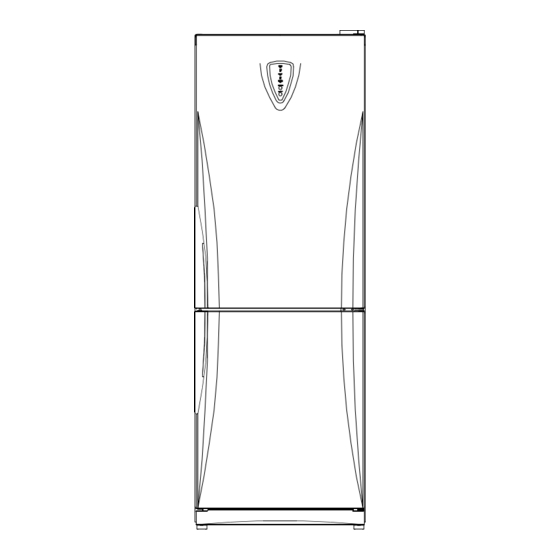
Page 5: Real View
3. REAL VIEW... -
Page 6: Machine Room View
4. MACHINE ROOM VIEW SCREW MACHINE... -
Page 7: Refrigerant Cycle
5. REFRIGERANT CYCLE CAPILLARY TUBE... -
Page 8: Temperatures Diagram
6. TEMPERATURES DIAGRAM Refrigerator SUPER : 0 ºC HIGH : 1 ºC : 3 ºC : 5 ºC : 6 ºC Low temp compartment : 3 ºC Vegetables compartment: 0 ºC~5 ºC Freezer: SUPER : -23 ºC HIGH : -22 ºC : -20 ºC : -18 ºC : -16 ºC... -
Page 9: Wiring Diagrams
7. WIRING DIAGRAMS 7.1- ERF-XX6A... - Page 10 7.2- ERF-XX6N...
-
Page 11: Pcb Circuit Diagrams
8. PCB CIRCUIT DIAGRAMS 8.1- ERF-XX6A... - Page 12 8.2- ERF-XX6N...
-
Page 13: Components Disassembly Pictures
9. COMPONENTS DISASSEMBLY PICTURES 1- FRONT PCB (FULL AUTOMATIC TYPE) - Input a cutter sleeve between Window FCP and Panel F control. Important: Input carefully cutter in the area that picture shows (down right). - Lift Window FCP up. * Remark: Input cutter deeply and carefully in order to lift up easily and avoid paint damages and scratches. - Page 14 - Unscrew the two fixing screws of F-PCB as. 2- SWITCH DOOR - Force switch door to the left side and input a thin driver in the rigth part as picture shows. After this operation, lift switch up. * Remark: Input driver carefully in order to lift up easily and avoid paint damages and scratches.
- Page 15 3- M-PCB - Unscrew the two fixing screws of cover PCB box. - Disconnect all housings connectors from M-pcb, and force plastic locker of pcb box in order to take out the pcb. * Remark: In ERF-xx6N models forced defrost button is located in M-PCB, so pcb box cover must be disassembled 4- RELAY BOX COVER...
- Page 16 5- MULTI DUCT - Take out window r pulling the top part sleeve. - Unscrew all fixing screws - To disassemble V-PCB force left plastic stopper and lift pcb up. - To disassemble R-sensor lift it up from the wires carefully.
- Page 17 6- LOUVERS: - Unscrew the two fixing screw for disassembly louver A and B TO DIASEMBLE IT IS NECESSARY A STAR DRIVER WITH A MINIMAL LENGHT OF 10 CM - Disconnect fan motor housing - Unscrew the fixing screw in order to disassemble Louver A.
- Page 18 L POSITION - When louvers are disassembled is very important check Knob F louver position. Default position is M L POSITION H POSITION 7-CHANGE DOOR OPEN SIDE - Unscrew cover T hinge - Before changing door open side, disconnect door housing connector.
-
Page 19: Door Position Change Process
10. DOOR POSITION CHANGE PROCESS STEP 1 : Remove door Follow to remove 1. Remove“ COVER HINGE” and “ HINGE T” 2. Remove“ R” door. 3. Remove “ HINGE M” 4. Remove“ F” door 5. Remove“COVER BRACKET” 6. Remove“ HINGE U” STEP 2 : Change door handle 7. - Page 20 door open side STEP 3 : Change the position of door 11. Attach the“ HINGE U” on the left. 12. Attach the“ F DOOR” 13. Reverse the position of “ HINGE M” and “ CAP SCREW HOLE” 1. Attach the“ R DOOR” 15.
-
Page 21: Explode Drawing
11. EXPLODE DRAWING... -
Page 23: Parts List
12. PARTS LIST MODEL NO PART NAME PART CODE REMARK 366N 366A 396N 396A 416N 416A 1 SHELF GLAS AS 3017839400 2 COVER GLAS C/C AS 3011497900 3 CASE CHILD 3011181400 NANO SILVER 4 DOOR CHILLED CASE 3011760500 NANO SILVER 5 COVER VEGTB CASE 3011497700 6 KNOB HUMIDITY... - Page 24 MODEL NO PART NAME PART CODE REMARK 366N 366A 396N 396A 416N 416A 37 BUTTON F-CP 3016304300 38 F-PCB AS 30143C6160 39 GASKET R DOOR AS 3012306600 3012306800 40 HANDLE R 3012640000 03 SILVER DMS2640010 SNOW WHITE 41 COVER HNDL SCREW 3011495200 03 SILVER DMS1495210...
- Page 25 MODEL NO PART NAME PART CODE REMARK 366N 366A 396N 396A 416N 416A 71 CASE VAPORY 3011162700 72 FIXTURE COMP 3012005300 73 DRYER ASSY 3016802203 74 COMPRESSOR DMS0A00100 75 ABSORBER COMP 3010103400 76 SCREW MACHINE DMS1B00100 77 SPECIAL WASHER DMS1B00200 78 PIPE CHARGE 3014418211 79 HARNESS EARTH...
-
Page 26: Pcb Control Function
13. PCB CONTROL FUNCTION 13.1. ERF-XXXA FUNCTION CONTENTS 1) VAC STEP LED ON: WHEN TEMP CONTROL S/W IS PRESSED 1 TIME. 2) LOW STEP LED ON: WHEN TEMP CONTROL S/W IS PRESSED 2 TIMES. 3) MID STEP LED ON: WHEN TEMP CONTROL S/W IS PRESSED 3 TIMES. 4) HIGH STEP LED ON: WHEN TEMP CONTROL S/W IS PRESSED 4 TIMES. - Page 27 1) TEMP. CONTROL SWITCH 1.1- TEMP. CONTROL When TEMP CONTROL button is pressed, the led lamps MIDLE - HIGH - SUPER - VAC -LOW - MIDDLE will be on in sequence. TEMPERATURE will be set if the button doesn’ t get pressed again within 5 sec 1.2- FORCED DEFROST: will be start when this button pushed for over 5 seconds continuously.
- Page 28 - Press TEMP. CONTROL button and make SUPER led lamp on. ON POINT: 0.05°C SUPER OFF POINT: -2.95°C 1) Starting condition of Defrost Mode 1.1- When accumulated running time of comp. Is 8, 10, 12, 18, 30hrs. 1.2- After Checking the condition ‘ 1.1’ if total time ( COMP on time + COMP off time) is more than 24, 36, 48, 72hrs, then defrost mode starts immediately.
- Page 29 - ERROR DISPLAY - When error happens, it is displayed on led lamp.(Main PCB LED 1) 1) R1 ERROR (It happens when R -SENSOR is OPEN or SHORT) 1.1- DISPLAY : On & off one time while LED is on. 1.2- CONTROL : Controlled by the condition of RT (Unit : min) RT-S TEMP...
- Page 30 1) START : Press POWER button 2) CANCELATION : Press POWER button again 3) DISPLAY POWER ON / OFF - START : All LED lamps are off and power is off.(COMP, Heater, Lamp of Room) - CANCEL : Return to the last condition(dial) MEMORY SAVING -After power failure or momentary power failure happens, if power is back on, the mode ON POWER...
- Page 31 1) R-SENSOR OFF POINT can be adjusted by changing the input voltage of MICOM 26 pin. 2) The default of input voltage is 0V. 3) The changed OFF POINT is base OFF POINT + OFF POINT of input voltage. R-SENSOR OFF POINT ADJUSTING 4) The change of R -SENSOR OFF POINT depend on the input voltage of MICOM...
- Page 32 13.2. ERF-XXXN FUNCTION CONTENTS - Temperature control of Refrigerator Maximum angle clockwise : Temperature setting for SUPER Maximum angle counter-clockwise : Temperature setting for VACATION Maximum rotation : 280±10° Minimum Step Difference : 0.7 deg/28° Total step Difference : 6.3 deg ERROR LED DISPLAY (ON MAIN PCB) DISPLAY ¦++Ù...
- Page 33 1) TEMPERATURE ADJUSTMENT 1.1- TEMPERATURE ADJUSTMENT TEMP CONTROL DIAL is rotated VAC , LOW, MIDDLE, HIGH, SUPER. TEMPERATURE will be set if the Dial doesn’ t get rotated again within 5 sec 1.2- FORCED DEFROST : Button of M-PCB(SW2) is pushed 1 time. 1.3- SHORT CIRCUIT OPERATION : Button of M -PCB(SW2) is pushed 2 times.
- Page 34 - Rotate TEMP. CONTROL Dial and make Super Location ON POINT: 0.05°C SUPER OFF POINT: -2.95°C - Starting condition of Defrost Mode - When accumulated running time of comp. is 8, 10, 12, 18, 30hrs. - After Checking the condition ‘ 2.1’ if total time(COMP on time + COMP off time) is more than 24, 48, 36, 72hrs, then defrost mode starts immediately.
- Page 35 * ERROR DISPLAY When error happens, it is displayed on led lamp.(Main PCB LED 1) 1) R1 ERROR (It happens when R -SENSOR is OPEN or SHORT) 1.1- DISPLAY : On & off one time while LED is on. 1.2- CONTROL : Contro lled by the condition of RT (Unit : min) RT-S TEMP RT-S ERROR...
- Page 36 1) Condition of LOW RT TEMP : 1.1- LOW RT A : RT SENSOR <14ºC 1.2- LOW RT B : 15ºC > RT-S < 19ºC 2) Control 2.1- When Comp. is on, R-SENSOR HTR is off. FUNCTION When it passes 6 min after COMP. is off, R-SENSOR HTR is on until COMP is on. 2.2- COMP.
- Page 37 5) APPLICATION (MAIN PCB) 5.1- GENERAL: MICOM 26 port - 0V 5.2- DELETE J2 (CHANGING R OFF POINT 1DEG UP) : MICOM 26 port – 2.5V R-SENSOR OFF POINT ADJUSTMENT (1 DEG. DOWN) J1 DELETION on LOW COOLING OPTION LOW COOLING Default resistance (31.4 KOhms) + 1.5 KOhms = 32.9 KOhms OPTION Operating on condition that R-SENSOR OFF point goes down 1ºC.
- Page 38 DAEWOO ELECTRONICS MANUFACTURING ESPAÑA S.A Polígono industrial de Júndiz C/Zurrupitieta 27, 01015 Vitoria, Spain Tel: 00 34 945292292 Fax:00 34 945290965...
Need help?
Do you have a question about the ERF-366A and is the answer not in the manual?
Questions and answers
My daewoo erf- 366a refrigerator doesn't freeze but power is fully on...it doesn't start. I only hear the wording. What could be the potential problem or solution to it
A Daewoo ERF-366A refrigerator that is powered on but not freezing could have several potential issues:
1. RT-Sensor Error: If the RT-SENSOR is open or shorted, the system will continue operating, but temperature control may not work properly. Check the LED display for an RT ERROR indication (blinking LED). If this error is present, replacing or fixing the RT-SENSOR may resolve the issue.
2. Defrost System Issue: If the defrost system does not function correctly, ice buildup could block airflow, preventing proper cooling. The system has an automatic start and stop defrost function. Check for excessive ice accumulation and ensure the defrost cycle is functioning.
3. Compressor or Fan Malfunction: The refrigerator uses a fan cooling system and a Sanyo CBE-140L5Z compressor. If either component fails, cooling performance will be affected. In test mode, the compressor and fan operate independently. Running a test could help diagnose if one of these components is not working.
4. Door Switch Issue: If the door switch malfunctions, the system may not detect when the door is closed, leading to improper cooling. A DR ERROR (continuous LED) indicates a door switch sensing failure. If the door switch works normally upon opening and closing, the error should clear automatically.
To troubleshoot:
- Check for error codes on the LED display.
- Inspect the RT-SENSOR for faults.
- Ensure the defrost system is functioning and no excessive ice is present.
- Test the compressor and fan operation.
- Verify the door switch is working correctly.
If none of these steps resolve the issue, professional servicing may be required.
This answer is automatically generated
My erf-367a doesn't freeze but power is fully on...and **** works
If the Daewoo ERF-366A is powered on but not freezing, possible issues could include:
1. RT Sensor Error: If the RT sensor is open or shorted, the system operates but temperature control may fail.
- Display: LED blinks twice while on.
- Control: Normal operation continues but without proper temperature regulation.
- Fix: Check the RT sensor and replace if faulty.
2. Defrost System Issue: The refrigerator has an automatic defrost system. If it fails, ice buildup may prevent proper cooling.
- Fix: Inspect defrost components, such as the heater or thermostat.
3. Compressor or Fan Malfunction: The cooling system relies on the compressor and fan.
- Fix: Check if the compressor and fan are running. If not, inspect wiring, relays, or replace faulty components.
4. Door Switch Issue: If the door switch is faulty, the system may not function correctly.
- Display: LED stays on continuously.
- Fix: Ensure the door switch is working properly.
5. Refrigerant Leak: The system uses R-134A refrigerant. Low refrigerant levels can prevent cooling.
- Fix: Check for leaks and refill refrigerant if needed.
If none of these resolve the issue, professional service may be required.
This answer is automatically generated