Table of Contents
Advertisement
Quick Links
Advertisement
Table of Contents

Subscribe to Our Youtube Channel
Related Manuals for CTC Union PHB-200


Summary of Contents for CTC Union PHB-200
- Page 1 PHB-200 SFP Patching Hub ...
- Page 2 ...
- Page 3 CTC Union Technologies Co., Ltd. Far Eastern Vienna Technology Center (Neihu Technology Park) 8F, No. 60 Zhouzi St. Neihu District Taipei 114 Taiwan Tel: +886‐2‐26591021 Fax: +886‐2‐27991355 Email: sales@ctcu.com techsupport@ctcu.com URL: http://www.ctcu.com PHB‐200 User Manual Fiber Managed Gigabit Ethernet Media Converter Concentrator Rack, 20 channels, 1U Version 1.0 August 16, 2013 (First Release) {This document will be updated when the SNMP option becomes available.} ...
- Page 4 Legal The information in this publication has been carefully checked and is believed to be entirely accurate at the time of publication. CTC Union Technologies assumes no responsibility, however, for possible errors or omissions, or for any consequences resulting from the use of the information contained herein. CTC Union Technologies reserves the right to make changes in its products or product specifications with the intent to improve function or design at any time and without notice ...
-
Page 5: Table Of Contents
Table of Contents Chapter 1 Introduction ................................. 7 1.0 Introduction ..................................7 1.1 Functional Description ................................. 7 1.2 Chassis Front Description..............................8 1.2.1 LED Indicators ................................8 1.3 Chassis Rear Description ..............................10 1.4 Chassis Physical Dimensions .............................. 10 1.5 Chassis Specifications................................. 11 Chapter 2 Installation ................................. 13 2.1 Introduction .................................. - Page 6 Table of Contents ii ...
-
Page 7: Chapter 1 Introduction
Ethernet fiber media converters concentrated into a single unit. PHB-200 provides a fixed, high density solution by placing 20 media converters in one manageable platform. A feature of PHB-200 allows it to detect the working or failing status either of two power supplies or any fan in the unit and activate relays that can be used to control external alarm devices. -
Page 8: Chassis Front Description
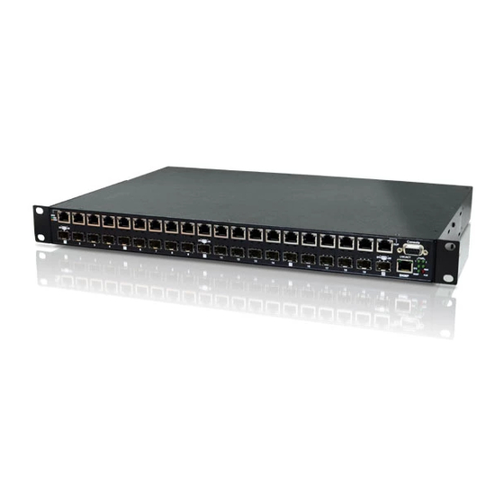
1.2 Chassis Front Description The front of PHB-200 has the SFP cages and RJ-45 pairs for each of the independent fiber media converters. Status LEDs provide real time state of fiber and UTP links. The DB9 female console port is RS-232 DCE for direct connection to PC COM port with 1:1 cable. -
Page 9: Chapter 1 Introduction
This RJ-45 port supports a 10/100M Ethernet connection for management when the optional SNMP module is installed in the PHB-200. Without the SNMP module, this connector is of no use and connects to nothing internally. There are two LEDs associated with this RJ-45 connector, a GREEN link indicator for presence or absence of LAN link and a GREEN activity indicator which will flash whenever there is LAN traffic on this port. -
Page 10: Chassis Rear Description
Terminal Strip Power Module 2 IEC AC Mains Input Power Module 1 for DC Power DC Type Shown AC Type Shown Figure 1‐2 Chassis Rear View 1.4 Chassis Physical Dimensions The following drawing shows the physical dimensions of the PHB-200. ... -
Page 11: Chassis Specifications
Chapter 1 Introduction 1.5 Chassis Specifications Environment Temperature 0 - 50°C (32-122°F) Humidity 5-95% non condensing Alarm relay contact ratings 125VAC 110VDC 0.6A 30VDC Power Supply Specifications AC Power Input : Universal, 100~240VAC ±10% (90~264VAC absolute) at ambient temperature Frequency : 47~63 Hz Output : DC 12V, 60W maximum rating (Green power rated, 89% power efficiency) DC Power Module Input : -36~60 VDC (option 1) - Page 12 Chapter 1 Introduction This page is blank intentionally. 12 ...
-
Page 13: Chapter 2 Installation
Earth Ground) central office power. The AC outlet should be capable of furnishing 100 to 240 VAC. Refer to 2.4 Electrical Installation. Allow at least 10cm (4 inch) clearance at the front of PHB-200 for the Fiber and other copper cables. -
Page 14: Electrical Installation
2.4 Electrical Installation With an AC power supply, AC power is supplied to PHB-200 through a standard IEC C14 3-prong receptacle, located on the rear of the unit. Any national power cord with IEC C13 line plug may be used to connect AC power to the power supply. -
Page 15: Chapter 3. Provisioning
3.3 Local Console Management The PHB-200 has a DB9 female "Console" port located on the front panel, right hand side of the unit. The RS-232 DCE (data communications equipment) port is designed for a direct 1:1 serial connection to a terminal or PC COM port and terminal emulation software. -
Page 16: Console Login
Connect the Personal Computer's COM port to the PHB-200's Console port using the provided DB9F to DB9M cable. Only 3-wire RS-232 is required, pins 2, 3 & 5 (RD, TD and SG). Power on the PHB-200, if not already powered on. The following login screen will be displayed. -
Page 17: Main Menu
Chapter 3 Provisioning 3.3.3 Main Menu The main menu is displayed in 5 sections, product header, version, alarm status, per port status and function group. **************************************** Product Header CTC UNION TECHNOLOGIES CO.,LTD Version PHB 200 Manager **************************************** Alarm Status Ver:[1.000-1.000-1.000] ... - Page 18 After making the change, press 's' to apply the change in the working memory and make it active. Later, remember to store the parameter changes by pressing 's' on the main menu page. If changes are not stored, they will be lost when the PHB-200 is powered off. ...
- Page 19 PHB-200 is powered off. <D> SFP DD Information : The DDI for SFP is described in SFF-8472 Multi-Source Agreement (MSA). The PHB-200 has the ability to read and display this information from any vendor SFP that follows SFF-8472. Display example: ...
-
Page 20: Device Functions
The device information includes the inventory and status of power supplies and of the cooling fans. The PHB-200 is available in 5 power options that include single AC, single DC, dual AC, dual DC and AC plus DC. In addition, DC supplies are offered in two different voltage ranges, an 18~36VDC or a 36~60VDC range. For operation with 24VDC, the lower range supply must be used. - Page 21 <Esc> Exit This setting will be applied immediately. Later, remember to store the parameter changes by pressing 's' on the main menu page. If changes are not stored, they will be lost when the PHB-200 is powered off. <3> Power Failure Alarm : ...
- Page 22 <T> All Port Configuration The PHB-200 has 20 isolated media converts all built into a single unit 19" rackmount chassis. This "All Port" provides a method to globally set all 20 converters to the same setting parameters. This can be very convenient if all the ports need to be active and set to the same fiber data rate.
- Page 23 3.3.5.6 Upgrade Firmware <U> Firmware Upgrade with Xmodem Occasionally there may be new firmware for the PHB-200 which could add new features or correct bugs found in the field. The PHB-200 supports field upgrade through the serial console port using Xmodem file transfer protocol.
- Page 24 Chapter 3 Provisioning 3. Use the TeraTerm Pro application to transfer the image file to the PHB‐200 for writing. 4. Follow the 'File' menu pull‐down, File > Transfer > XMODEM > Send. (Be very sure to use only the Xmodem protocol) a. The firmware image should be located just one directory "up" from the TeraTerm application in the upgrade package. b. Select the image file c. Click the 'Open' button. ...
- Page 25 Chapter 3 Provisioning 6. After the image transfer is completed and the image is written in the device, the PHB‐200 will automatically reboot. The login prompt will again be displayed. Check the firmware version. Version explanation: a.aaa‐b.bbb‐c.ccc where; a.aaa is the H/W (hardware) version, in this example version 1.000 b.bbb is the F/W (firmware) version of the master CPU, in this example version 1.000 c.ccc is the F/W (firmware) version of the 5 slave CPUs, in this example version 1.000 If the slave CPU version shows "?.???", it indicates one or more of the CPU versions mismatch or have checksum error. In this case the upgrade should be run again. ...
- Page 26 Chapter 3 Provisioning This page was left blank intentionally 26 ...
-
Page 27: Chapter 4 Snmp
4.1 Introduction The PHB-200 has the option of an additional hardware module to provide SNMP management capability. This module uses an embedded system, interfaces directly with the PHB-200 hardware and provides user interfaces for Telnet (text menu), Web graphical user interface, and for SNMP protocol using enterprise MIB. -
Page 28: Web Manager Operation
Chapter 4 SNMP 4.2.2 Web Manager Operation PHB-200 with SNMP supports web based management. Use your favorite browser (Chrome, Firefox, Internet Explorer or Safari) and connect to PHB-200 by using the SNMP's IP address. 28 ... - Page 29 Chapter 4 SNMP 29 ...
-
Page 30: Chapter 5 Troubleshooting
Chapter 5 Troubleshooting Chapter 5 Troubleshooting 5.1 Introduction {This chapter will be added in a later revision of the document.} 30 ... -
Page 31: Chapter 5 Troubleshooting
Chapter 5 Troubleshooting 31 ... - Page 33 ...
- Page 34 ...
Need help?
Do you have a question about the PHB-200 and is the answer not in the manual?
Questions and answers