Table of Contents
Advertisement
Quick Links
MC-302E PG2
PowerG Wireless, Door/Window Contact
with Wired Input
1. INTRODUCTION
The MC-302E PG2 is a two-way wireless PowerG magnetic contact device. The device includes a
built-in reed switch (that opens upon removal of a magnet placed near it) and an auxiliary hard-wired
input, programmable as either N.O., N.C. or E.O.L., for use with additional sensors – pushbuttons
detectors, door contacts, etc.
The MC-302E PG2 can be configured through the PowerMaster control panel to allow the installer to
disable the magnet-operated reed switch if only the auxiliary input is needed. The reed switch and the
auxiliary input behave as separate transmitters, although they trigger the same RF transmitter. The
MC-302E PG2 sends the parameters of the specific alarm to the control panel using PowerG two-way
communications protocol.
The MC-302E PG2 tamper switch is activated when the cover is removed.
A periodic supervision message is transmitted automatically. The control panel is thus informed, at
regular intervals, of the unit's active participation in the system.
An LED lights whenever alarm or tamper events are reported. The LED does not light while a
supervision message is being transmitted.
Operating power is obtained from an on-board 3 V Lithium battery. When the battery voltage is low, a
"low battery" message is sent to the receiver.
2. INSTALLATION
2.1 Mounting
(Fig. 3a and 3b)
It is highly recommended to attach the transmitter to the top of the door/window on the fixed frame and the magnet to the movable part
(door or window). Make sure that the magnet is located not more than 6 mm (0.25 in.) from the transmitter's marked side.
Note: Once the cover is removed, a tamper message is transmitted to the receiver. Subsequent removal of the battery prevents
transmission of "TAMPER RESTORE", leaving the receiver in permanent alert. To avoid this, press the tamper switch while you remove
the battery.
Caution!
Risk of explosion if battery is replaced by an incorrect type. Dispose of used battery according to manufacturer's instructions.
Attention! The unit has a back tamper switch (optional) under the PCB. As long as the PCB is seated firmly within the base, the switch
lever will be pressed against a special break-away base segment that is loosely connected to the base (Figures 2 and 3a). Be sure to
fasten the break-away segment to the wall. If the detector unit is forcibly removed from the wall, this segment will break away from the
base, causing the tamper switch to open
B
A
F
E
A. Flexible Retainer
B. Break-away base segment (for Back Tamper)
C. P.C. board edge supports
D. Mounting holes
E. Wiring inlet
F. Plastic standoff for case closure screw
Figure 2. Base with P.C. Board Removed
D-303384 MC-302E PG2 Installation Instructions
.
D
Installation Instructions
C
Figure 3a. Mounting
Note: 868 MHz device is illustrated in the above example. The
same mounting procedure should be performed for 433 MHz and
915 MHz devices.
* This screw is used for back tamper only.
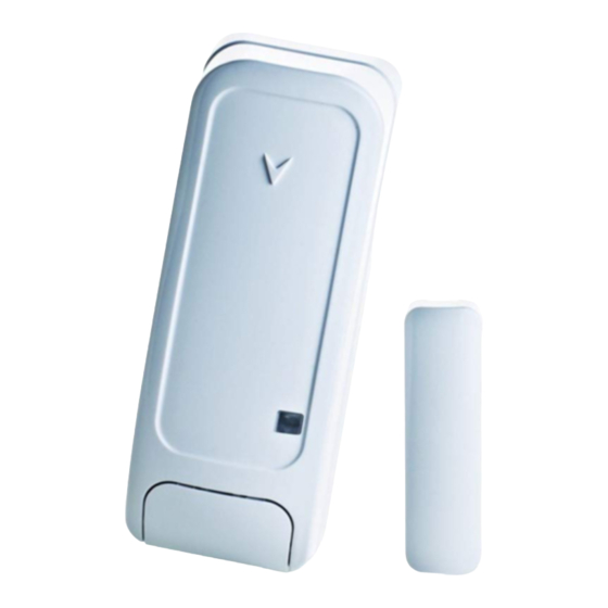
A. Transmission LED
B. Magnet
Figure 1: External View
1
Advertisement
Table of Contents

Related Manuals for Visonic MC-302E PG2


Summary of Contents for Visonic MC-302E PG2
-
Page 1: Installation Instructions
N.O., N.C. or E.O.L., for use with additional sensors – pushbuttons detectors, door contacts, etc. The MC-302E PG2 can be configured through the PowerMaster control panel to allow the installer to disable the magnet-operated reed switch if only the auxiliary input is needed. The reed switch and the auxiliary input behave as separate transmitters, although they trigger the same RF transmitter. - Page 2 [2] Select the "Device Settings" option and refer to section 2.3 to configure the magnetic contact device parameters. 2.3. Configuring the Magnetic Contact Device Parameters DEVICE SETTINGS Enter the menu and follow the configuration instructions for the MC-302E PG2 magnetic contact device as described in the following table. Option Configuration Instructions Determine whether or not the alarm LED indication will be activated.
- Page 3 Note: For detailed Diagnostics Test instructions refer to the control panel Installer Guide. 4. MISCELLANEOUS COMMENTS Visonic Ltd. wireless systems are very reliable and are tested to high standards. However, due to low transmitting power and limited range (required by FCC and other regulatory authorities), there are some limitations to be considered: A.
-
Page 4: Alarm Input
WARNING! The user is cautioned that changes or modifications to the unit, not expressly approved by Visonic Ltd., could void the user’s FCC or other authority to operate the equipment. The technical documentation as required by the European Conformity Assessment procedure is kept at: UNIT 6 MADINGLEY COURT CHIPPENHAM DRIVE KINGSTON MILTON KEYNES MK10 0BZ.
Need help?
Do you have a question about the MC-302E PG2 and is the answer not in the manual?
Questions and answers