Advertisement
Quick Links
MC- - - - 302V
MC
302V PG2
MC
MC
302V
302V
Supervised Vanishing Magnetic Contact Device
1. INTRODUCTION
1. INTRODUCTION
1. INTRODUCTION
1. INTRODUCTION
The MC-302V PG2 is a very thin PowerG magnetic contact device
that is compatible with PowerMaster control panels. The device
includes a built-in reed switch (that opens upon removal of a
magnet placed near it). The MC-302V PG2 sends the alarm
message to the control panel using PowerG 2-way communications
protocol.
A periodic supervision or alarm message is transmitted
automatically. The control panel is thus informed, at regular
intervals, of the unit's active participation in the system.
The LED lights green/yellow/red, according to signal strength,
upon first insertion of the battery and for the test period of 15 min.
LED does not light while a supervision message is being transmitted.
Operating power is obtained from an on-board 3 V Lithium
battery. When the battery voltage is low, a "low battery" message
is sent to the receiver.
The MC-302 V is available for 433 MHz, 868 MHz, and 915 MHz.
2 2 2 2 . INSTALLATION
. INSTALLATION
. INSTALLATION
. INSTALLATION
CAUTION: This equipment shall be installed by Service Personnel in non-hazardous indoor locations only.
2.1 Mounting
A.
Enroll button B. Double-sided adhesive tape
Note: The required battery is CR2032 Lithium 3V, manufactured by VARTA or another UL-recognized manufacturer, purchased from a
Visonic-approved supplier.
Note: To comply with FCC and IC RF exposure compliance requirements, the device should be located at a distance of at least 20 cm
from all persons during normal operation. The antennas used for this product must not be co-located or operated in conjunction with
any other antenna or transmitter.
1. Insert a "quarter" coin in the slot, as shown in the drawing, and flex to remove the cover
- or, if a "quarter" coin is not available -
2. Insert a 4 mm flat screwdriver into the slot of the plastic cover, as shown in the drawing, and flex the slot to open that side of the
plastic cover.
3. Insert the screwdriver into the slot on the other side of the plastic cover and repeat the procedure, and then remove the cover.
4. Insert the battery at an angle (see drawing) while observing battery polarity and then press down on the battery.
Caution! Risk of explosion if battery is replaced by an incorrect type. Dispose of used batteries according to the manufacturer's instructions.
5. Peel away the release liners from the two strips of double-sided adhesive tape and attach to the device and magnet.
6. Align the device with the magnet according to the location marks and fasten the device and magnet to the mounting surface.
transmitter should be mounted on the fixed surface and the magnet on the moving surface.
7. For installers of 433 or 868 MHz model:
Ensure that the heads of the tightened screws are flat perpendicular to the device surface.
D-304535 MC-302V PG2 Installation Guide
PG2
PG2
PG2
Figure 2: Mounting
Installation Instructions
7
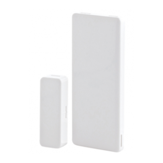
A. Transmission LED
B. Magnet
Figure 1:
External View
7
The
1
Advertisement

Related Manuals for Visonic MC-302V PG2


Summary of Contents for Visonic MC-302V PG2
- Page 1 1. INTRODUCTION 1. INTRODUCTION 1. INTRODUCTION The MC-302V PG2 is a very thin PowerG magnetic contact device that is compatible with PowerMaster control panels. The device A. Transmission LED includes a built-in reed switch (that opens upon removal of a B.
- Page 2 Europe: EN 300220, EN 301489 EN 50130-4, EN 61000-6-3, EN 60950-1 The MC-302V PG2 is compatible with the RTTE requirements - Directive 1999/5/EC of the European Parliament and of the Council of 9 March 1999 and EN50131-1 Grade 2 Class I.
- Page 3 433/868 MHz model: 62 x 25.4 x 7.7 mm (2-1/2 x 1 x 1/3 in.) 915 MHz model: 62 x 25.4 x 6.1 mm (2-1/2 x 1 x 1/4 in.) Weight (including battery) 12g (0.42 oz) Color White or brown D-304535 MC-302V PG2 Installation Guide...
- Page 4 WARRANTY Visonic Limited (the “Manufacturer") warrants this product only (the "Product") to the original purchaser only (the However, if the Manufacturer is held liable, whether directly or indirectly, for any loss or damage arising under “Purchaser”) against defective workmanship and materials under normal use of the Product for a period of this limited warranty, THE MANUFACTURER'S MAXIMUM LIABILITY (IF ANY) SHALL NOT IN ANY CASE twelve (12) months from the date of shipment by the Manufacturer.
Need help?
Do you have a question about the MC-302V PG2 and is the answer not in the manual?
Questions and answers