Table of Contents
Advertisement
Quick Links
DL
DL-125
-125C C C C
DL
DL
-125
-125
Programmable 2-Channel Speech Dialer
1 1 1 1 . INTRODUCTION
. INTRODUCTION
. INTRODUCTION
. INTRODUCTION
1.1 Purpose and Use
The DL-125C is an automatic programmable speech dialer with
two alarm inputs. It is designed for verbal reporting of two
separate events, one event per input. Each event can be reported
to 4 different remote telephones, or both events can be reported
to the same 4 telephones. The telephone numbers of the called
parties may be frequently reprogrammed by the user.
A communication session with the first / second group of tele-
phones is initiated by triggering alarm inputs Z-1 / Z-2, or by
pressing AL-1 / AL-2 on the front panel, respectively. The alarm
logic of each input is programmed separately by the installer.
Pulse or DTMF dialing can be used to establish communication
with the called party, in accordance with the local telephone
network. The dialer performs certain functions in response to
DTMF control commands received from remote telephones.
Whenever a message is acknowledged by the called party, the
dialer activates a highly sensitive microphone, to allow the called
party to monitor the installation site for sound. The "listening-in"
period is limited in time, but the called party can send a specific
DTMF command to prolong it.
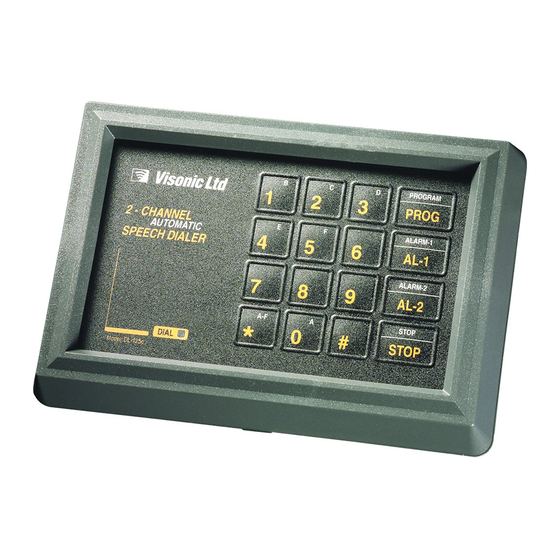
The DL-125C is packaged in a plastic case, with a built-in keypad
for programming and operation (see Figure 1). 12 keys serve for
entering data, and 4 are function keys. Programmed data is
retained in an EEPROM, unaffected by power failures.
Two models are available (12 V or 24 V versions upon request):
DL-125C - allows the user to stop the communication session by
pressing the STOP pushbutton (provided that momentary alarm
contacts are used).
DL-125 CA - does not allow the user to stop the communication
session by pressing the STOP pushbutton. This feature is
sometimes required by regulatory authorities.
Each model is available in two versions - one for 12 VDC input and
the other for 24 VDC input. Power is obtained from an external
source, preferably backed up by a rechargeable battery.
1.2 Applications
•
Upgrading alarm control panels that do not have a dialer. Two
different events can be reported to remote telephones.
•
Stand-alone 2-input 24-hour alarm system, triggered directly
by a smoke/shock detectors or a panic button (loop response
time 200 ms).
•
Looking after infants or old, sick and disabled people. The
DL-125C delivers a distress message and then allows the
called party to "listen in".
•
Supervising unattended technical devices or processes, with
verbal reporting of equipment failures or process anomalies.
•
Transmitting numeric reports to numeric pagers or voice
messages to voice pagers.
1.3 Message Structure
The overall length of the speech message that can be recorded is
limited to 20 seconds. Within this limit, the message can be
composed of two pre-recorded segments:
• The identification segment, common to both alarm inputs. This
segment usually identifies the user or the protected premises.
Note: Recording an identification segment is not obligatory. You
can record a longer alarm type segment for each input instead.
• The alarm type segment, associated with a specific alarm input.
This segment is used to describe the type of event reported
("fire", "intrusion", "panic", etc.).
A transmission initiated by a specific event (one of the two
alarms) is composed of the identification segment and one of
two alarm type segments. The order of transmission of the two
segments can be selected. For instance, you can select: "The
Smith residence, 25 Scarecrow Drive – Fire Alarm", or you can
select: "Fire Alarm – the Smith residence, 25 Scarecrow Drive".
DE5803
Installation Instructions
Figure 1. DL-125C, Front Panel
1.4 Communication Routine
Note: In this section, location numbers identify "memory cells"
that retain programmed parameters (see Para. 4.7).
Once triggered into action, the DL-125C introduces a program-
med pre-dialing pause (see Location 14 in Para. 4.7). Then it
disconnects the local telephone set and engages the telephone
line. The DIAL LED lights and the process continues as follows:
A. The dialer starts dialing if uninterrupted tone is detected for 2
seconds (see C below). If 5 seconds elapse with no dial tone -
the dialer disengages the line, waits 5 seconds and tries
again. If another 5 seconds go by without dial tone, the dialing
procedure starts anyway (see B below).
B. The dialer checks whether a letter is programmed as a prefix
to the first telephone number. Letter prefixes impose an
additional delay before dialing (see Para. 4.2). The dialer
introduces the required delay (if any) and then starts dialing.
C. The dialer dials the programmed number. During dialing, the
LED either remains lighted (DTMF dialing) or flashes (pulse
dialing), depending on the dialing method selected. After
dialing, the dialer pauses for 5 seconds and transmits the
message prepared for the called party associated with the
input that had been triggered.
Note: Message structure is explained in Section 1.3.
D. The dialer now waits 3 seconds for the called party to
acknowledge (the acknowledge signal is DTMF "1").
E. Upon receiving the acknowledge signal, the dialer removes
the presently contacted telephone from its task list for the
current event. If the "listen in" function is permitted (see
Location 10 in Para. 4.7) it will continue as in Paragraphs F
and G below. If not, the dialer will go "on hook" and proceed to
dial the next number.
Note: Without an acknowledgement, the message will be
repeated until the maximum number of message repeats is
reached (see Location 20 in Para. 4.7). The DL-125 will call
the remaining numbers and will then repeatedly retry the
number that didn't acknowledge, until the maximum number of
dialing attempts is reached (see Locations 12 and 13).
F. After acknowledgement, the dialer enables the "listen in"
function for a preprogrammed period.
G. At the end of the listen-in period, a short beep sounds. If the
called party keys "1" within 10 seconds, a new listen-in period
begins. Otherwise", the dialer will go "on hook". The listen-in
period may be prolonged as many times as necessary or
terminated at any time by keying "9" twice in succession.
H. Upon conclusion of the communication session with the first
telephone, the procedure in A through G above will be
repeated for all remaining telephone numbers in the relevant
1
Advertisement
Table of Contents

Subscribe to Our Youtube Channel
Related Manuals for Visonic DL-125C


Summary of Contents for Visonic DL-125C
-
Page 1: Installation Instructions
DTMF command to prolong it. Note: In this section, location numbers identify "memory cells" The DL-125C is packaged in a plastic case, with a built-in keypad that retain programmed parameters (see Para. 4.7). for programming and operation (see Figure 1). 12 keys serve for Once triggered into action, the DL-125C introduces a program- entering data, and 4 are function keys. - Page 2 . INSTALLATION . INSTALLATION 3.1 Mounting The DL-125C may be installed as a stand-alone unit or within the housing of a host system such as an alarm control panel. The unit includes three parts: the front frame, the electronic module (complete with keypad) and the base.
-
Page 3: Programming Fundamentals
- one for the pager's phone number and another for the whichever comes first, and continue numeric data sent to the pager. Since each DL-125C input has 4 dialing. memory locations for phone numbers, each input can report to one pager and 2 regular telephones or just two pagers. -
Page 4: Programming Chart
PIN, separating characters required etc.). 4.6. Programming Summary Figure 7 depicts a typical arrangement of data in the DL-125C memory for reporting an event to a pager. In this example, the The DL-125C can be programmed equally well in the installer's phone number is entered into memory location No. -
Page 5: Fcc Requirements
If the dialer is in the non-backup mode (“0” has been necessary. selected Location 24), press the STOP button (DL-125C) or B. If a predialing pause has not been programmed, the DIAL disconnect the power (DL-125CA) to prevent further dialing. -
Page 6: Appendix A. User Information
APPENDIX A. USER INFORMATION APPENDIX A. USER INFORMATION A.1 User Guidance We recommend to photo-copy this section for all DL-125C users - the proprietor of the protected premises and all called parties. A.2 Data Record WARRANTY Visonic Ltd. and/or its subsidiaries and its affiliates ("the Manufacturer") warrants its The Manufacturer does not represent that its Product may not be compromised and/or products hereinafter referred to as "the Product"...
Need help?
Do you have a question about the DL-125C and is the answer not in the manual?
Questions and answers