Visonic MC-302 PG2 Installation Instructions
Powerg, wireless, door/window contact
Hide thumbs
Also See for MC-302 PG2:
- Installation instructions manual (9 pages) ,
- Installation instructions (4 pages) ,
- Accessories manual (46 pages)
Table of Contents
Advertisement
Quick Links
MC
MC
MC
MC- - - - 302
302
302
302 PG2
PowerG, Wireless, Door/Window Contact
1. INTRODUCTION
1. INTRODUCTION
1. INTRODUCTION
1. INTRODUCTION
The MC-302 PG2 is a fully supervised, PowerG magnetic contact device. The device includes a built-
in reed switch (that opens upon removal of a magnet placed near it). The MC-302 PG sends the
parameters of the specific alarm to the control panel using PowerG 2-way communications protocol.
The MC-302 PG 2 tamper switch is activated when the cover is removed.
A periodic supervision message is transmitted automatically. The control panel is thus informed, at
regular intervals, of the unit's active participation in the system.
An LED lights whenever alarm or tamper events are reported. The LED does not light while a
supervision message is being transmitted.
Operating power is obtained from an on-board 3 V Lithium battery. When the battery voltage is low, a
"low battery" message is sent to the receiver.
2 2 2 2 . INSTALLATION
. INSTALLATION
. INSTALLATION
. INSTALLATION
2.1 Mounting (Fig. 3a and 3b)
It is highly recommended to attach the transmitter to the top of the door/window on the fixed frame and the magnet to the movable part
(door or window). Make sure that the magnet is located not more than 6 mm (0.25 in.) from the transmitter's marked side.
Note: Once the cover is removed, a tamper message is transmitted to the receiver. Subsequent removal of the battery prevents
transmission of "TAMPER RESTORE", leaving the receiver in permanent alert. To avoid this, during the enrolling process, press the
tamper switch while you remove the battery.
Caution!
Risk of explosion if battery is replaced by an incorrect type. Dispose of used battery according to manufacturer's instructions.
Attention! The unit has a back tamper switch (optional) under the PCB. As long as the PCB is seated firmly within the base, the switch
lever will be pressed against a special break-away base segment that is loosely connected to the base (Figures 2 and 3a). Be sure to
fasten the break-away segment to the wall. If the detector unit is forcibly removed from the wall, this segment will break away from the
base, causing the tamper switch to open
B
A
F
E
A. Flexible Retainer
B. Break-away base segment (for Back Tamper)
C. P.C. board edge supports
D. Mounting holes
E. Wiring inlet
F. Plastic standoff for case closure screw
Figure 2. Base with P.C. Board Removed
WARNING! To comply with FCC and IC RF exposure compliance
requirements, the magnet contact device should be located in a
distance of at least 20 cm from all persons during normal operation.
The antennas used for this product must not be co-located or
operated in conjunction with any other antenna or transmitter.
D-302412 MC-302 PG2 Installation Instructions
PG2
PG2
PG2
.
D
Installation Instructions
2
C
Figure 3a. Mounting
Note: 868 MHz device is illustrated in the above example. The
same mounting procedure should be performed for 433 MHz and
915 MHz devices.
* This screw is used for back tamper only.
1. Remove screw
2. Separate base from cover.
3. Flex catch and remove P.C. board
4. Mark & drill 2 holes in mounting
surface.
Fasten base with 2 countersunk
screws.
5. Mount the magnet near its location
mark with 2 screws
A. Enroll button
B. Fixed frame
C. Moving part
B
A
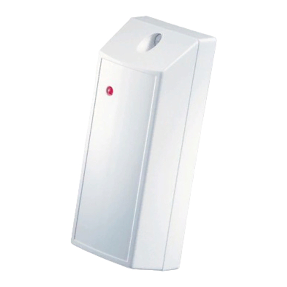
A. Transmission LED
B. Magnet
Figure 1: External View
1
A
*
3
4
B
C
5
Figure 3b. Mounting
1
Advertisement
Table of Contents

Related Manuals for Visonic MC-302 PG2


Summary of Contents for Visonic MC-302 PG2
- Page 1 1. INTRODUCTION 1. INTRODUCTION The MC-302 PG2 is a fully supervised, PowerG magnetic contact device. The device includes a built- in reed switch (that opens upon removal of a magnet placed near it). The MC-302 PG sends the parameters of the specific alarm to the control panel using PowerG 2-way communications protocol.
- Page 2 [2] Select the "Device Settings" option and refer to section 2.4 to configure the magnetic contact device parameters. 2.4. Configuring the Magnetic Contact Device Parameters DEVICE SETTINGS Enter the menu and follow the configuration instructions for the MC-302 PG2 magnetic contact device as described in the following table. Option Configuration Instructions Here you determine whether or not the alarm LED indication will be activated.
- Page 3 MISCELLANEOUS COMMENTS MISCELLANEOUS COMMENTS Visonic Ltd. wireless systems are very reliable and are tested to high standards. However, due to low transmitting power and limited range (required by FCC and other regulatory authorities), there are some limitations to be considered: A.
- Page 4 JS-700930 WARRANTY Visonic Limited (the “Manufacturer") warrants this product only (the "Product") to the original However, if the Manufacturer is held liable, whether directly or indirectly, for any loss or purchaser only (the “Purchaser”) against defective workmanship and materials under normal...
Need help?
Do you have a question about the MC-302 PG2 and is the answer not in the manual?
Questions and answers