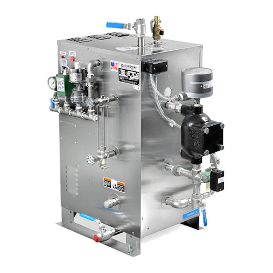
Sussman ES series Installation, Operation And Maintenance Manual
Electric boiler
Hide thumbs
Also See for ES series:
- Installation, operation and maintenance manual (24 pages) ,
- Installation, operation and maintenance manual (24 pages)
Table of Contents
Advertisement
Model No.
_____________________________________
Boiler Serial No.
_______________________________
National Board No.
___________________________
Safety Valve Set Pressure
Power Circuit Voltage
_______________________
Control Circuit Voltage
______________________
Amps
Phase
__________
_________
Steam Outlet Valve Size
_____________
This data file contains the National
IMPORTANT:
Board Registration Certificate approving your boiler.
It must be kept near the boiler at all times.
Products covered by this manual:
_________________________________________________________________________________
KW
Max
Series
Range
Steam Rate*
_________________________________________________________________________________
ES, HU 12-180
36-542 lbs/hr 1.2-18.4
_________________________________________________________________________________
*Steam Rate: Steam at 212˚ F with 50˚ F feed water
ES and HU boilers are of Carbon Steel construction.
See page 23 for Water Quality Information.
IMPORTANT NOTE:
As you follow these instructions, you will notice warning and caution symbols. This blocked information is important for the safe and efficient
WA R N I N G
states a hazard which
may cause serious injury or death if precautions
are not followed.
_______________ PSIG
HZ
__________
NPT
Design
BHP
Pressure
0-100 psig
C A U T I O N
minor injury or product damage may occur if you
do not follow instructions.
A Division of Sussman-Automatic Corporation
43-20 34th Street, Long Island City, NY 11101 • (718) 937-4500
1-800-238-3535 • Fax: (718) 937-4676 • email: seb@sussmancorp.com
www.sussmanboilers.com
ES & HU Installation, Operation
and Maintenance Manual
TABLE OF CONTENTS
Component Identification . . . . . . . . . . . . . . . . . 2
Dimensional & Clearing Specifications. . . . . . . . . 3
Wiring Diagrams . . . . . . . . . . . . . . . . . . . . . . . . . 4-7
Installation
Piping. . . . . . . . . . . . . . . . . . . . . . . . . . . . . . . . . . 8
Wiring . . . . . . . . . . . . . . . . . . . . . . . . . . . . . . . . . 9
Pre-Operation Check . . . . . . . . . . . . . . . . . . . . . . . 10
Pressure Controls, Operation & Testing . . . . . . . 10
Operation. . . . . . . . . . . . . . . . . . . . . . . . . . . . . . . . 11
Blowdown . . . . . . . . . . . . . . . . . . . . . . . . . . . . . . . 11
Digital Timer Operation Instructions. . . . . . . . . . 12
Timing Switch . . . . . . . . . . . . . . . . . . . . . . . . . . . . 13
Maintenance . . . . . . . . . . . . . . . . . . . . . . . . . . . . . 13
Work
Pressure
85 psig
Condensate Return Systems . . . . . . . . . . . . . . . . 16
Blowdown Separator Tanks . . . . . . . . . . . . . . . . . 17
Specification Charts . . . . . . . . . . . . . . . . . . . . . . . 18
Sizing . . . . . . . . . . . . . . . . . . . . . . . . . . . . . . . . . . . 19
Gauge Glass Installation . . . . . . . . . . . . . . . . . 20-21
Element Replacement . . . . . . . . . . . . . . . . . . . . . . 22
for Carbon Steel Boilers . . . . . . . . . . . . . . . . . . 23
signals a situation where
. . . . . . . . . . . . . . . . 14
. . . . . . . . . . . . . 14
. . . . . . . . . . . . . 14
. . . . . . . . . . . . . . . . . . 14
. . . . . . . . . . . . . . . . . . . 15
. . . . . . . . . . . . . . . . 15
. . . . . . . . 15
. . . . . . . . . . . . . . . . . . . . . 15
. . . . . . . . 15
IMPORTANT NOTE:
This highlights information that is especial-
ly relevant to a problem-free installation.
M A D E I N U S A
PUR 101137 4.13
Advertisement
Table of Contents

Related Manuals for Sussman ES series


Summary of Contents for Sussman ES series
-
Page 1: Table Of Contents
A Division of Sussman-Automatic Corporation 43-20 34th Street, Long Island City, NY 11101 • (718) 937-4500 M A D E I N U S A 1-800-238-3535 • Fax: (718) 937-4676 • email: seb@sussmancorp.com PUR 101137 4.13... -
Page 2: Dimensional Information And Component Identification
Installation, Operation & Maintenance Manual Dimensional Information & Component Identification Models: ES, HU Height W idth Length _________________________________ _______________________________________ ___________________________________ WATER STEAM SYMBOL ITEM ES12-18 ES24-72 ES100 ES135-180 _______________________________________ MODEL INLET OUTLET Height Overall Height 36" 44" 59" 61" __________________________________________________________________ ES 12, 18;... -
Page 3: Dimensional & Clearing Specifications
Installation, Operation & Maintenance Manual Dimensional & Clearance Specifications Pressure High Limit Operating Gauge Steam Outlet Pressure Pressure Control Control Safety Valve On/Off Sw itch Gauge Glass Assembly Height Liquid Level Control W ater Feed Inlet Drain Valve Left Front W idth Length Side Elevation... -
Page 4: Wiring Diagrams
Installation, Operation & Maintenance Manual Typical Wiring Diagrams: a. Three phase power circuit with separate 120Volt control circuit. (With singe phase power circuit insert.) b. Three phase power circuit with step down transformer. c. Detailed ES81017MR auxiliary low water cut off wiring. d. -
Page 5: Installation
Installation, Operation & Maintenance Manual Wiring Diagram Control Circuit ES Electric Boilers (Basic Control Circuit) 120V 1PH INPUT FIELD WIRING CONTROL TERMINAL FACTORY WIRING BLOCK ON-OFF SWITCH PILOT SOLENOID VALVE LIGHT PUMP MOTOR RELAY OPERATING HIGH LIMIT CONTACTORS LIQUID PRESSURE PRESSURE LEVEL CONTROL... -
Page 6: Installation
Installation, Operation & Maintenance Manual Wiring Diagram Control Circuit ES Electric Boilers with Sequencer 120V 1PH INPUT CONTROL FIELD WIRING TERMINAL BLOCK FACTORY WIRING ON-OFF SWITCH PILOT SOLENOID VALVE LIGHT PUMP MOTOR RELAY 120V COM HIGH LIMIT OPERATING LIQUID PRESSURE PRESSURE LEVEL CONTROL... - Page 7 Installation, Operation & Maintenance Manual Wiring Diagram Control Circuit ES Electric Boilers with Automatic Blowdown System 120V 1PH INPUT FIELD WIRING FACTORY WIRING CONTROL TERMINAL BLOCK PILOT LIGHT 7-DAY 24-HR OPEN TIMER CLOSE ES81600 MOTORIZED AUTOMATIC BLOWDOWN TIME DELAY RELAY BLOWDOWN SYSTEM VALVE ON-OFF...
-
Page 8: Piping
Installation, Operation & Maintenance Manual Installation REFER TO NATIONAL AND ALL APPLICABLE LOCAL CODES FOR SPECIFIC INSTALLATION REQUIREMENTS. 1. The boiler should be mounted on a solid, level foundation. 2. The boiler should be located with suitable clearances, refer to page 3 and Code requirements. NOTE: Allow minimum of 21 inches clearance in front of door for servicing of heating elements. -
Page 9: Wiring
Installation, Operation & Maintenance Manual Wiring ALL ELECTRICAL WIRING MUST BE PERFORMED BY A QUALIFIED ELECTRICIAN IN ACCORDANCE WITH NATIONAL AND LOCAL ELECTRICAL CODES. C A U T I O N Assure that the power voltage and phase being supplied to the boiler matches the power voltage and phase of the boiler. -
Page 10: Pre-Operation Check
Installation, Operation & Maintenance Manual Pre-Operation Check (All Boilers) LWCO/PUMP CONTROL OPERATION AND TESTING 1. All valves for incoming water supply are to be fully opened. Boilers equipped with an auxiliary low water cut-off Main disconnect switch is to be in the "on" position. Boiler main control with a manual re-set button (required as switch is to be in the "on"... -
Page 11: Operation
Installation, Operation & Maintenance Manual Operation C A U T I O N With main disconnect “OFF” tighten all ing pressure control set point, at which time the con- electrical connections before energizing boiler to prevent tactor(s) will de-energize. arcing, carbonizing of contact and/or overheating 7. -
Page 12: Digital Timer Operation Instructions
Installation, Operation & Maintenance Manual Digital Timer - Operation Instructions TO SET TIME & DAY OF CLOCK 1. Press Menu ON/OFF STATUS Í 2. 24h AM or PM blinking, press ON symbol displayed when timer is on and OFF + or – to select, press OK symbol displayed when timer is off. -
Page 13: Timing Switch
Installation, Operation & Maintenance Manual 24-Hour and 7-Day Time Switches Maintenance C A U T I O N HAZARD OF ELECTRIC SHOCK. DISCONNECT ALL ELECTRICAL POWER BEFORE PROGRAMMING WORKING ON BOILER. F or electric steam boilers equipped with Automatic ussman Electric Steam Boilers are designed for years of trou- Blowdown Systems ble-free performance. -
Page 14: Standard Equipment
Installation, Operation & Maintenance Manual Standard Equipment for ES & HU Optional Equipment AUXILIARY LOW WATER CUT OFF HIGH PRESSURE WATER FEED SYSTEM • For model ES12-72 PN ES38002A • For model ES & HU boilers PN ES81017MR (with manual reset). •... -
Page 15: Vacuum Breaker Systems
Installation, Operation & Maintenance Manual Optional Equipment (cont.) VACUUM BREAKER SYSTEMS BLOWDOWN SEPARATORS (see page 17) • For model ES boilers PN ES89369 • For models ES12-48 - PN BDT-ASME36 A vacuum breaker will prevent a boiler from flooding as a •... -
Page 16: Condensate Return Systems
Installation, Operation & Maintenance Manual Condensate Return Systems Models 38083V & 38084V " DIA COVER PLATE EASY ACCESS FOR MAINTENANCE " VENT WITH SAFETY BAR VENT SAFETY BAR VENT (label) COLD WATER INLET CONDENSATE RETURN FLASH TUBE (label) 1/2" COLD WATER INLET COUPLING FLOAT VALVE LIMIT MAKEUP WATER PRESSURE WITH #100 MESH STRAINER... -
Page 17: Blowdown Separator Tanks
4" 2" 18" 54" The Sussman Separator design incorporates a water seal at Maximum Boiler Working Pressure: 250 psi the outlet which permits the operator to introduce cold Maximum Blowdown Separator Pressure: 65 psi water from the bottom to mix with the hot water and boil- Blowdown Separators are sized in accordance with National Board Standards er steam blowdown in the separator. -
Page 18: Specification Charts
Installation, Operation & Maintenance Manual Steam Gauge Specifications Pressure/ __________________________________________ Temperature Chart ________________ Boiler Lbs/Hr 3-Ph Model No. KW Rating Steam** Volts*** Amps __________________________________________ Gauge Temperature Pressure F˚ C˚ ________________ PSIG ES-12* 1.22 36.2 __________________________________________ ________________________ ________________________ ES-18* 1.84 54.2 ________________________ __________________________________________ ________________________... -
Page 19: Sizing
Installation, Operation & Maintenance Manual Sizing Use the following Table to determine KW Boiler rating when steam load and feedwater temperatures are known. ___________________________________________________________________ Feed Water ___________________________________________________________________ ( F˚) .3347 .3355 .3375 .3388 .3406 .3422 .3431 .3447 .3458 .3464 .3470 ___________________________________________________________________ .3318 .3326... -
Page 20: Gauge Glass Installation
Installation, Operation & Maintenance Manual Gauge Glass Installation IMPORTANT NOTE: Read all warnings and instructions before performing installation or maintenance. Safety glass- Top Gauge es and gloves should be worn at all times when working Fitting with or examining water gauge glass and connections. Pressure in generator to be at zero before proceeding. -
Page 21: Gauge Glass Installation
Installation, Operation & Maintenance Manual Gauge Glass Installation - Use and Care DO NOTs MAINTENANCE Examine the gauge glass regularly for any signs of • DO NOT use glass if it contains any scratches, chips, or clouding, scratching, erosion, or corrosion. The glass any other visible signs of damage. -
Page 22: Element Replacement
Installation, Operation & Maintenance Manual Element Replacement READ INSTRUCTIONS COMPLETELY BEFORE STARTING WORK C A U T I O N Before Installing your new elements be sure the McDonnell Miller low water cut-off and aux. low water cutoff (if sup- Boiler w ith 1”Steam Equalizing Pipe plied) is operating properly. -
Page 23: Water Quality Information For Carbon Steel Boilers
Installation, Operation & Maintenance Manual Water Quality Information for Carbon Steel Boilers For optimum results, the feedwater supply should be tested prior to initial start-up. If the mineral content exceeds the following recommended limits, various external treatment processes (water softener, reverse osmosis, etc.) may be used to correct the problem. NOTE: An analysis of the on-site boiler feedwater must be made by a recognized and reliable water treatment company to ascertain the existing condition and treatment required. - Page 24 A Division of Sussman-Automatic Corporation 43-20 34th Street, Long Island City, NY 11101 • (718) 937-4500 M A D E I N U S A 1-800-238-3535 • Fax: (718) 937-4676 • email: seb@sussmancorp.com PUR 101137 4.13 www.sussmanboilers.com...
Need help?
Do you have a question about the ES series and is the answer not in the manual?
Questions and answers