Table of Contents
Advertisement
Quick Links
Model No. SSB- __________________
Boiler Serial No. _________________
National Board No.
Safety Valve Set Pressure________psig
Power Circuit Voltage
Control Circuit Voltage ___________
Amps _____ Phase _____ HZ ______
IMPORTANT: This data file contains the National Board
Registration Certificate approving your boiler. It must be
kept near the boiler at all times.
SSB Boilers have Stainless Steel all wetted metal parts. SSB
boilers shall be operated using only deionized water, having
a maximum conductance of 1 microSiemen per cm
(1 S/cm) [minimum specific resistivity of 1 megohm per cm
(1ΜΩ/cm)].
PRODUCTS COVERED BY THIS MANUAL:
Series
KW Range
Steam Rate*
______________________________________________________________________
SSB
12-180
36-542 lbs/hr 1.2-18.4 0-100 psig
*Steam Rate- Steam @ 212 F with 50 F feed water
IMPORTANT NOTE:
As you follow these instructions, you will notice warning and caution symbols. This blocked information is important for the safe and efficient
WA R N I N G
states a hazard
which may cause serious injury or
death if precautions are not followed.
______________
____________
BHP
Design Pres.
C A U T I O N
minor injury or product damage may occur
if you do not follow instructions.
A Division of Sussman-Automatic Corporation
43-20 34th Street, Long Island City, NY 11101 • 718-937-4500
1-800-238-3535 • Fax: 718-937-4676 • email: seb@sussmancorp.com
www.sussmanboilers.com
SSB Installation, Operation
and Maintenance Manual
TABLE OF CONTENTS
Component Identification . . . . . . . . . . . . . . . . . 2
Dimensional & Clearing Specifications . . . . . . . . . 3
Wiring Diagrams . . . . . . . . . . . . . . . . . . . . . . . . . 4-5
Piping, Wiring . . . . . . . . . . . . . . . . . . . . . . . . . . . 6
Pre-Operation Check . . . . . . . . . . . . . . . . . . . . . . . . 7
Pressure Controls, Operation & Testing . . . . . . . . 7
Operation. . . . . . . . . . . . . . . . . . . . . . . . . . . . . . . . . 8
Blowdown . . . . . . . . . . . . . . . . . . . . . . . . . . . . . . . . 8
Timing Switch . . . . . . . . . . . . . . . . . . . . . . . . . . . . . 9
Digital Timer Operation Instructions. . . . . . . . . . 10
Maintenance . . . . . . . . . . . . . . . . . . . . . . . . . . . . . 11
Optional Equipment . . . . . . . . . . . . . . . . . . . . . . . 12
Max
Work Pres.
Blowdown Separator Tanks . . . . . . . . . . . . . . . . . 14
85 psig
Specification Charts . . . . . . . . . . . . . . . . . . . . . . . 15
Sizing . . . . . . . . . . . . . . . . . . . . . . . . . . . . . . . . . . . 16
Gauge Glass Installation. . . . . . . . . . . . . . . . . . . . 17
Gauge Glass Use and Care . . . . . . . . . . . . . . . . . . 18
Element Replacement . . . . . . . . . . . . . . . . . . . . . . 19
signals a situation where
. . . . . . . . . . . . . . . . 12
. . . . . . . . . . . . . 12
. . . . . . . . . . . . . 12
. . . . . . . . . . . . . . . . 12
. . . . . . . . . . . . . . . . . . . . . 13
IMPORTANT NOTE:
This highlights information that is especially
relevant to a problem-free installation.
M A D E I N U S A
PUR 101137SSB
. . . . . . . . 13
. . . . . . . . 13
3/13
Advertisement
Table of Contents

Related Manuals for Sussman SSB 12-18


Summary of Contents for Sussman SSB 12-18
-
Page 1: Table Of Contents
A Division of Sussman-Automatic Corporation 43-20 34th Street, Long Island City, NY 11101 • 718-937-4500 M A D E I N U S A 1-800-238-3535 •... -
Page 2: Dimensional Information And Component Identification
Installation, Operation & Maintenance Manual Dimensional Information & Component Identification Model SSB _________________________________ _______________________________________ ___________________________________ WATER STEAM SYMBOL ITEM SSB12-18 SSB 24-72 SSB 100 SSB 135-180 _______________________________________ MODEL INLET OUTLET ⁄ ⁄ Steam Outlet " 10" " 9" __________________________________________________________________ SSB 12–18 37"... -
Page 3: Dimensional & Clearing Specifications
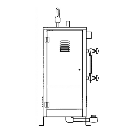
Installation, Operation & Maintenance Manual Dimensional & Clearance Specifications Steam Outlet Operating High Limit Pressure Safety Valve Pressure Pressure Gauge Control Control On/Off Sw itch Gauge Glass Liquid Level Assembly Control Height W ater Feed Drain Valve Inlet Left Front W idth Length Side Elevation... -
Page 4: Wiring Diagrams
Installation, Operation & Maintenance Manual Wiring Diagram Control Circuit 120V 1PH INPUT Control Terminal Block Pilot Light 7-Day 24 Hr Open Timer Close ES81600 Motorized Automatic Blowdown Blowdown System Time Delay Relay Valve ON/OFF SWITCH SOLENOID PILOT VALVE LIGHT PUMP MOTOR RELAY CONTACTORS OPERATING... -
Page 5: Wiring Diagrams
Installation, Operation & Maintenance Manual Wiring Diagram Power Circuit FIELD WIRING THREE PHASE SINGLE PHASE MAIN POWER MAIN POWER SUPPLY FACTORY WIRING SUPPLY L1 L2 TERMINAL POWER BLOCK TB 1 (see note 1) PILOT LIGHT POWER FUSES (see Note 2) 480V 120V CONTACTORS... -
Page 6: Installation
Installation, Operation & Maintenance Manual Wiring Installation ALL ELECTRICAL WIRING MUST BE PERFORMED BY A QUAL- REFER TO NATIONAL AND ALL APPLICA- IFIED ELECTRICIAN IN ACCORDANCE WITH NATIONAL AND BLE LOCAL CODES FOR SPECIFIC INSTAL- LOCAL ELECTRICAL CODES. LATION REQUIREMENTS. C A U T I O N Assure that the power voltage and phase being 1. -
Page 7: Pre-Operation Check
Installation, Operation & Maintenance Manual Pre-Operation Check (All Boilers) LWCO/PUMP CONTROL OPERATION AND TESTING 1. All valves for incoming water supply are to be fully at this time. Close the drain valve, water feed system opened. Main disconnect switch is to be in the will automatically refill the boiler and the contactors "on"... -
Page 8: Operation
Installation, Operation & Maintenance Manual Operation C A U T I O N With main disconnect “OFF” tighten 6. Boiler steam pressure will gradually increase to all electrical connections before energizing boiler to the operating pressure control set point, at which time the contactor(s) will de-energize. -
Page 9: Timing Switch
Installation, Operation & Maintenance Manual Digital Timer - Operation Instructions TO SET TIME & DAY OF CLOCK 1. Press Menu ON/OFF STATUS Í 2. 24h AM or PM blinking, press ON symbol displayed when timer is on and OFF + or – to select, press OK symbol displayed when timer is off. -
Page 10: Digital Timer Operation Instructions
Installation, Operation & Maintenance Manual 24-Hour and 7-Day Time Switches PROGRAMMING F or electric steam boilers equipped with Automatic Blowdown Systems ES 81600, refer to the following instruc- tions for time clock operation and settings. Timer settings for blowdown operation are at the discretion of the owner/operator. -
Page 11: Maintenance
Installation, Operation & Maintenance Manual Maintenance C A U T I O N HAZARD OF ELECTRIC SHOCK. DISCONNECT ALL ELECTRICAL POWER BEFORE WORKING ON BOILER. ussman Electric Steam Boilers are designed for years of trou- cleaned and reinstalled. ble-free performance. To establish a good preventative mainte- 11. -
Page 12: Standard Equipment
Installation, Operation & Maintenance Manual Standard Equipment Optional Equipment AUXILIARY LOW WATER CUT OFF HIGH PRESSURE WATER FEED SYSTEM • For model SSB boilers SSB81017MR • For model SSB12-72 PN SSB38002 (with manual reset). • For model SSB100-180 PN SSB38020 Used to supply makeup water and to maintain con- Senses water level electronically using a resistance stant water level when the boiler operating pressure... -
Page 13: Blowdown Separators
Installation, Operation & Maintenance Manual Optional Equipment (cont.) MULTISTAGE LOAD PROGRESSIVE BLOWDOWN SEPARATORS (see page 14) SEQUENCERS • For models SSB12-48 PN BDT-ASME36 Accurate control is provided by automatic progressive • For models SSB60-180 PN BDT-ASME42 sequencing in the use of energy and minimizing wear on A separator accepts the flash steam and effluent electrical components. -
Page 14: Blowdown Separator Tanks
" 2" 18" 42" The Sussman Separator design incorporates a water Maximum Boiler Working Pressure: 250 psi seal at the outlet which permits the operator to Maximum Blowdown Separator Pressure: 65 psi introduce cold water from the bottom to mix with... -
Page 15: Specification Charts
Installation, Operation & Maintenance Manual Specifications STEAM GAUGE PRESSURE/ __________________________________________ TEMPERATURE CHART ________________ Boiler Lbs/Hr 3-Ph Gauge Temperature __________________________________________ Model No. KW Rating Steam** Volts*** Amps Pressure F˚ C˚ ________________ PSIG SSB-12* 1.22 36.2 ________________________ __________________________________________ ________________________ SBS-18* 1.84 54.2 ________________________ __________________________________________ ________________________... -
Page 16: Sizing
Installation, Operation & Maintenance Manual Sizing Use the following Table to determine KW Boiler rating when steam load and feedwater temperatures are known. _____________________________________ ____________________ Feed Water ___________________________________ ______________________ ( F˚) .3347 .3355 .3375 .3388 .3406 .3422 .3431 .3447 .3458 ___________________________________ ______________________ .3318 .3326... -
Page 17: Gauge Glass Installation
Installation, Operation & Maintenance Manual Gauge Glass Installation IMPORTANT NOTE: Read all warnings and instruc- tions before performing installation or Top Gauge maintenance. Safety glasses and gloves should be Fitting worn at all times when working with or examining water gauge glass and connections. Pressure in gener- ator to be at zero before proceeding. -
Page 18: Gauge Glass Use And Care
Installation, Operation & Maintenance Manual Gauge Glass Installation - Use and Care DO NOTS MAINTENANCE Examine the gauge glass regularly for any signs • DO NOT use glass if it contains any scratches, chips, or of clouding, scratching, erosion, or corrosion. The any other visible signs of damage. -
Page 19: Element Replacement
Installation, Operation & Maintenance Manual Element Replacement READ INSTRUCTIONS COMPLETELY BEFORE STARTING WORK C A U T I O N Before Installing your new elements be sure the low water cut-off and aux. low water cutoff (if supplied) is operating properly. 1”Steam Equalizing Pipe The float chamber and lower equalizer column of the liquid level control must be completely clear of sludge or other foreign matter. - Page 20 M A D E I N U S A A Division of Sussman-Automatic Corporation PUR 101137SSB 3/13 43-20 34th Street, Long Island City, NY 11101 • 718-937-4500 1-800-238-3535 • Fax: 718-937-4676 • email: seb@sussmancorp.com www.sussmanboilers.com...
Need help?
Do you have a question about the SSB 12-18 and is the answer not in the manual?
Questions and answers