Table of Contents
Advertisement
Advertisement
Table of Contents

Related Manuals for aoyue Int701A++


Summary of Contents for aoyue Int701A++
- Page 1 ® ® AOYUE 701A++ 701A++ Advanced Repairing System INSTRUCTION MANUAL Thank you for purchasing Aoyue Int701A++ Repairing System. It is important to read the manual before using the equipment. Please keep manual in accessible place for future reference.
-
Page 2: Table Of Contents
This manual is designed to familiarize and instruct the operator with the proper usage and maintenance of the equipment. The “Care and Safety Precautions” section explains the hazards of using any type of soldering or reworking device. Please read carefully and observe the guidelines in order to maximize usage and minimize the risk of injury or accidents . -
Page 3: Product Description
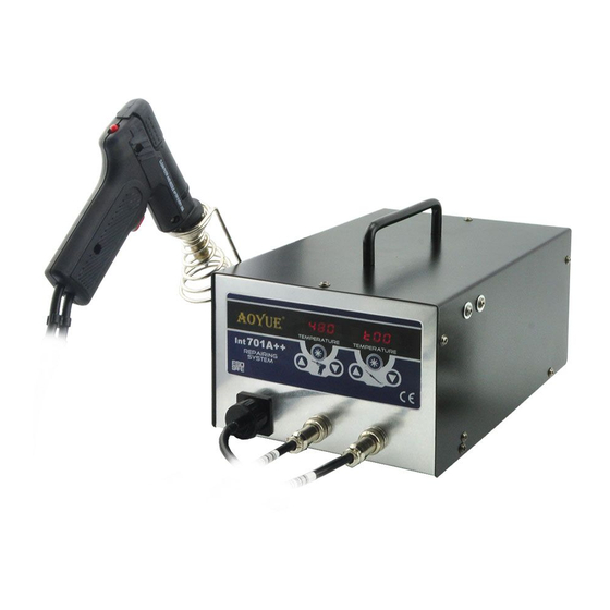
PRODUCT DESCRIPTION The Aoyue I 701A++ Advanced Repairing System is a reworking equipment that combines the functionality of 70W Soldering Iron, Smoke Absorber, and Desoldering Gun in one package. The dual port system of the Int701A++ allows simultaneous use of the desoldering gun and soldering iron. -
Page 4: Specifications
SPECIFICATION MAIN STATION Power Input : available in 110V / 220V Station Dimensions: 188(w) x 126(h) x 250(d) mm Weight: 5.6Kg SOLDERING IRON Power Consumption: Temperature Range: 200°C - 480°C Heating Element: Ceramic Heater Output Voltage: DESOLDERING GUN Power Consumption: Temperature Range: 200°C - 480°C Heating Element:... -
Page 5: Package Inclusion
PACCKAGE INCLUSIONS 1 unit 701A++Main Station 1 pc. B003A Soldering Iron with Smoke Absorbing function 1 pc. B1002A Desoldering Gun with 301212 tip (1.8mm) 1 pc. 2660 Soldering Iron Stand** 1 pc. 201252 Spring Filter 1 pc. 30201X Suction/Vacuum Cover 2 pcs. -
Page 6: Safety Precautions
SAFETY PRECAUTIONS CAUTION: Improper usage can cause serious injury to personnel and/or damage to equipment. For your own safety, please observe the ff. precautions. Check each component after opening the package to make sure ● everything is in good condition. If there are any suspected damage, do not use the item and report the issue to your vendor. -
Page 7: Assembly And Preparation
ASSEMBL Y and PREPARATIONS A. Main Station As soon as the equipment has been removed from the package, REMOVE THE SCREW located at the center of the bottom of the main unit. This screw holds the pump in place during transportation. WARNING: Failure to remove the screw before using the equipment can cause damage to the system. -
Page 8: Control Panel Guide
CONTROL PANEL GUIDE LEGEND: 1 — Desoldering Gun Temperature Display 2 — Soldering Iron Temperature Display 3 — Soldering Iron function button 4 — Desoldering Gun function button 5 — Soldering Iron Temperature Control Buttons 6 — Desoldering Gun Temperature Control Buttons 7 —... -
Page 9: Operating Guidelines
OPERATING GUIDELINES IMPORTANT REMINDERS: 1. Make sure the equipment is placed on a flat stable surface and all the heat-generating components placed on their respective holders or stands. 2. Ensure all terminal connections are properly secured. IMPORTANT: Please refer to the CONTROL PANEL GUIDE page for buttons and display panel directory. - Page 10 OPERATING GUIDELINES 7. Start using the soldering iron as soon as desired temperature is reached. 8. To deactivate the SMOKE ABSORBER function, simultaneously press both up and down button of the soldering iron temperature adjustment button (“5” from the control panel). 9.
- Page 11 OPERATING GUIDELINES 7. Check the tip temperature with an external temperature sensor, adjust temperature settings higher or lower for the right temperature. Or recalibrate at the desired temperature level 8. Ensure that all the solder is melted before triggering the pump. (Partially melted solder will still be sucked up however it would clog the barrel).
-
Page 12: Auto-Sleep Functions
AUTO SLEEP FUNCTIONS Auto-Sleep Mode (Soldering Iron and Desoldering Gun) The sleep timer can be configured to power down the soldering iron or desoldering gun after a defined time. When in sleep mode three dashes “ - - - “ will be shown indicating that it is now in sleep mode. To reactivate the simply push its corresponding function or adjustment button.\ By default the system’s sleep duration is 0 indicating the sleep timer... -
Page 13: Digital Calibration
DIGITAL CALIBRATION A. Utilizing the Solder Iron Digital Temperature Calibration By default, the system is properly calibrated but for some cases when a little adjustment of the soldering iron temperature is required the following procedure can be done. 1. Turn on the soldering iron function. 2. - Page 14 DIGITAL CALIBRATION B. Utilizing the Desolder Gun Digital Temperature Calibration By default, the system is properly calibrated but for some cases when a little adjustment of the desoldering gun temperature is required the following procedure can be done. 1. Turn on the desoldering gun function. 2.
-
Page 15: Digital Calibration
DIGITAL CALIBRATION Solder Iron Digital Temperature Calibration Example The external temperature sensor displays 250 degrees. ● The set temperature and displayed actual temperature of the ● soldering iron is 300 degrees. 300 — 250 = 50. An additional adjustment of 50 degrees is ●... -
Page 16: Care And Maintenance
CARE and MAINTENANCE Blower/Vacuum Air Terminal Filters Filters should be cleaned and replaced regularly to avoid dirt which can clog the air passage. More importantly, this will also effectively clean the toxic fumes produced during soldering process. Soldering Iron Tip Always keep the solder-plated section of the tip/nozzle coated with a small amount of solder. - Page 17 CARE and MAINTENANCE Vacuum Air Terminal Filters Filters should be cleaned and replaced regularly to avoid dirt which can clog the air passage. More importantly, this will also effectively clean the toxic fumes produced during soldering process. De-Soldering Gun 1. Before usage dampen the filter pads with a little bit of water to allow efficient air passage and filter action, re- Filter Pads dampen pads frequently for maximum efficiency.
-
Page 18: Care And Maintenance
CARE and MAINTENANCE De-Soldering Gun Disassembled illustration: Filter Pipe Filter Pads Spring Filter Filter Pipe B a c k H o l d e r Heating Element Assembly Tip Lock Desoldering Gun Body Tip Cylinder Heat Guard Assembly Desoldering Trigger Changing Desoldering Tip: 1. -
Page 19: Basic Troubleshooting Guide
CARE and MAINTENANCE Changing Filter Pad and Spring Filter: 1. Unlock the Filter Pipe by toggling the Press down Release Knob Release Knob. The Back Holder F i l t e r Assembly would spring back to P i p e allow easy extraction of the Filter Pipe Assembly which houses the Filter Pipe Cap, Spring Filter, Filter Pipe and Filter... - Page 20 CARE and MAINTENANCE WARNING: Unplug the power cord before starting this procedure. Replacing the Heating Element Unscrew the Tip Lock and pull out Tip Cylinder together with Lock remove Desoldering Tip. Tip Cylinder Heating Element Desoldering Tip Tip Lock Remove the Filter Pipe Assembly. Loosen the 3 fastening screws on the plastic handle and separate the housing.
- Page 21 CARE and MAINTENANCE Cleaning the Desoldering Tip CAUTION: The desoldering gun will be extremely hot. During maintenance, please wear proper protection and work carefully. Step 1 cleaning passes completely through the hole. Step 2 Insert the bit while turning it clockwise. Step 3 Pull the drill bit out straight without turning it.
- Page 22 SPARE PARTS LIST ⑩ ⑨ ⑪ ⑫ ⑧ ⑦ ⑬ ③ ⑥ ② ④ ① ⑤ ⑭ Part No. Part Name 30129 Desoldering Gun Tip Cylinder with Tip Lock ① 302082 Desoldering Tip 1.0MM 302092 Desoldering Tip 1.5MM ② 301212 Desoldering Tip 1.8MM C005A Desoldering Gun Heating Element...
- Page 23 BASIC TROUBLESHOOTING GUIDE PROBLEM 1: THE UNIT HAS NO POWER Check if the unit is switched ON. Power switch located at the back. Check the fuse. Replace with the same type if fuse is blown. Check the power cord and make sure there are no disconnections. Verify that the unit is properly connected to the power source.
- Page 24 They can take this product for environmental safe recycling. Manufacturer: AOYUE INTERNATIONAL LIMITED Jishui Industrial Zone, Nantou, Zhongshan City, Guangdong Province, P.R.China http://www.aoyue.co...
Need help?
Do you have a question about the Int701A++ and is the answer not in the manual?
Questions and answers