Table of Contents
Advertisement
Advertisement
Table of Contents

Related Manuals for Raymarine Remote display


Summary of Contents for Raymarine Remote display
- Page 1 Remote Display...
- Page 2 Remote Display EMC Conformance All Raymarine equipment is designed to the best industry standards for use in the recreational marine environment. The design and manufacture of Raymarine equipment conforms to the appropriate Electromagnetic Compatibility (EMC) standards. Correct installation is required to ensure that performance is not compromised.
-
Page 3: Table Of Contents
4.2 Speed Calibration - 4.3 Wind Calibration - 4.4 Compass Calibration and Alignment - Installation 5.1 Changing the Bezel - 5.2 Cradle - Maintenance and Fault Finding 6.1 Care and Maintenance - 6.2 Fault Finding and Technical Support - Warranty Information www.raymarine.com... -
Page 4: Introduction
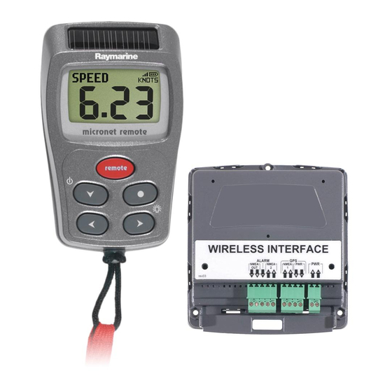
All data available on your Micronet network can be viewed wherever you are located on your vessel. Remote control of Micronet displays The Remote Display can control the other Micronet displays on your network, i.e. Maxi, Dual Maxi and remote enabled models of the Digital, Dual Digital and Analogue displays. -
Page 5: Power Management And Battery Life
Information Power Management and Battery Life What makes your Micronet display possible is Raymarine’s revolutionary approach to power management. By reducing the amount of power being used by the electronics and maximizing the potential of the sun to provide power, a Micronet display becomes a virtually perpetual device. -
Page 6: Safety And Disposal
Sleep Mode If there is no boat speed or change in heading registered on the system for a period of 12 hours your Remote Display will switch off to conserve power. A "POWER SAVE" alarm will sound before the system switches off. -
Page 7: Operation
Setup and Calibration has been performed correctly before attempting to use your Micronet system. Display Information Switching the System On and Off To switch your Micronet system on or off select any display and press button for 2 seconds. Switch on Switch off www.raymarine.com... -
Page 8: Information Display Operation
Remote Display Information Display Operation Information is displayed in a "Chapter and Page" format using the button to scroll through the chapters and the buttons to move between the pages within a chapter. The diagram below shows the information format. -
Page 9: Remote Control Operation
Operation Default Chapter and Page diagram Remote Control Operation In this mode, the Remote Display is able to control the functions of other displays on the Micronet network. All remote control screens are displayed in "reverse", with white text on a black background, to allow immediate recognition of remote control mode. -
Page 10: Backlighting
The full range of operation and configuration functions on the controlled display is available by pressing keys on the Remote Display. Note: The first press of on the remote display... -
Page 11: Keylock
The depth value that triggers the alarm is affected by any keel or waterline offsets that have been added. See page 21 S4 to set the alarm function. This alarm does not sound as the depth increases above the preset alarm level. www.raymarine.com... -
Page 12: Information Display - Data Item Descriptions
Remote Display Depth Deep Alarm The water depth has increased above or fallen below the preset alarm level. The depth value that triggers the alarm is affected by any keel or waterline offsets that have been added. See page 21 s5 to set the alarm function. - Page 13 See page 24 S18 to set an offset. A WIND KNOTS/M S (Apparent wind Speed) The apparent wind speed with respect to the vessel as measured by the Wind Transmitter, displayed in the currently selected wind units. See page 23 S11 to select wind units. www.raymarine.com...
- Page 14 Remote Display A WIND PORT/STBD (Apparent wind angle) The apparent wind angle with respect to the vessel as measured by the Wind Transmitter. T WIND KNOTS/M S (True wind speed) The true wind speed with respect to the vessel, calculated by the display taking into account the vessels speed through the water.
- Page 15 See Raymarine's "Using wind shifts to your advantage" sheet for further information, this is available on the Raymarine web site, www.raymarine.com. 16 HEADING Current magnetic compass heading of the vessel as measured by the Compass Transducer.
- Page 16 Remote Display COG (Course over the ground) The vessel's course over the ground as calculated by the GPS Antenna or a GPS receiver. LAT (Latitude) The vessel's current latitude as calculated by the GPS Antenna or a GPS receiver. LON (Longitude) The vessel's current longitude as calculated by the GPS Antenna or a GPS receiver.
- Page 17 After the countdown is completed, the timer will automatically start to count the elapsed time and this will continue until the button is pressed and held for 2 seconds. www.raymarine.com...
- Page 18 Remote Display Press and hold Press to store to enter the timer select the desired the countdown time setup countdown time Press to start Countdown in Press to reset the countdown progress timer to the nearest whole minute TIME Current time as received from the GPS Antenna, corrected to local time if an offset has been added.
- Page 19 FFD-1 to FFD-6 (Custom data displays) If you have a Wireless (NMEA) Interface connected to a PC with Raymarine proprietary NMEA output capability (PTAK) then your six user defined free format pages will be displayed in these custom data display pages.
-
Page 20: Setup And Calibration
Remote Display Setup and Calibration Entering Setup and Calibration Mode To enter the Setup and Calibration menu press and hold for 2 seconds button. Note: It is not possible to enter setup mode while the Race Timer is currently visible on a single item display page. Scroll to a different page in order to enter setup. - Page 21 The parameter option will begin to flash. Use the buttons to select the option required. Press the button again to set the new option. To toggle between ON/OFF parameter settings: Press the button. The setting will toggle between ON and OFF. www.raymarine.com...
-
Page 22: Setup Chapter And
Remote Display Setup Chapter and Page Organisation The diagram below shows the Setup and Configuration chapter and page organisation. For a full description of each setup parameter refer to items S1 to S47 on the following pages. www.raymarine.com... -
Page 23: 3.5 Setup Parameter Descriptions
(see page 22 -s10 to select units) and are all subject to any keel or waterline offset added (see page 23 s18 to set an offset). This alarm sounds as the depth increases past this value or decreases past this value. www.raymarine.com... - Page 24 Remote Display High Wind Alarm Sets the wind speed at which the display will alarm. The options are: Off and 0.0 to 100 knots (0.0 to 51.4 m/s). Values are displayed in the previously selected units (see page 22 S11 to select units).
- Page 25 Allows a keel offset to be added allowing the display depth reading to indicate depth below the bottom of the boat, or a waterline offset allowing the depth reading to indicate actual water depth. See page 31 to set a depth offset. www.raymarine.com...
- Page 26 Remote Display Wind Page Wind Response Sets the update period of the wind display. The options available are: Auto/Slow/Medium/Fast. Wind Angle Aligns the displayed apparent wind angle with the actual wind direction with respect to the boat. See page 33 for the calibration process.
- Page 27 If a single line page is set to display the OFF (null) data item, the page concerned is removed from the cycle of single line display pages. If all single line display pages are set to display the OFF (null) data item, the whole single line display chapter is removed from the chapter cycle. www.raymarine.com...
- Page 28 Remote Display Four-Line Display Page This page permits the selection of a four-line display page to configure. To select a four-line display page to configure: Press repeatedly until the desired page is next to the cursor . Press to configure the page.
- Page 29 ON and OFF. Modify Control List The Remote Display builds a list of the Micronet displays on the network that are configured for remote control. This list allows the user to select a display to control with the Remote Display.
- Page 30 Remote Display To alter the position of a display in the list of controllable displays: Press the button to scroll down the list. The sequence number of the display in the list of controllable displays is shown by the cursor.
- Page 31 Software Version/Network Nodes The top line of each Health chapter screen shows the software version of the Remote Display, battery level and charge rate to assist in troubleshooting and fault finding. If the display is the "Master" (the one used to switch on the system) then the number of items (nodes) in the system will be shown.
- Page 32 Remote Display Mast Rotation Transmitter Signal Strength As above but for the Mast Rotation Transmitter MOB Transmitter Signal Strength As above but for MOB Transmitter Type 6 to Type 9 Signal Strength For possible future use. www.raymarine.com...
-
Page 33: Seatrial And Calibration
Press the button to enter Edit Mode, the parameter value will flash. Press the buttons to change the value. Press the button to exit Edit Mode. Press and hold the button to exit Setup and return to normal operation. www.raymarine.com... -
Page 34: Speed Calibration
Setup and return to normal operation. Should you be unable to carry out this procedure due to strong tidal conditions or poor GPS information there is further information regarding Speed Calibration using a measured distance on the Raymarine website at www.raymarine.com. www.raymarine.com... -
Page 35: Wind Calibration
The display will indicate the percentage correction factor entered. Press the button to exit Edit Mode. Press and hold the button to exit Setup and return to normal operation. www.raymarine.com... -
Page 36: Compass Calibration And Alignment
Remote Display Compass Calibration and Alignment To ensure that inaccuracies caused by metallic and magnetic objects on the boat are kept to a minimum it is necessary to calibrate or swing the compass. A deviation caused by surrounding objects will be compensated for and the compass reading may be set to the correct heading. -
Page 37: Installation
Each Remote Display is supplied with 2 cradles. It is recommended that one of these is mounted in a in a sunny or well illuminated place, so that the Remote Display can be left to “recover” during the day in case it has been used extensively at night. -
Page 38: Maintenance And Fault Finding
Remote Display Maintenance and Fault Finding Care and Maintenance All Micronet products are totally sealed against water and are not serviceable. Any attempt to take a Micronet product apart will invalidate the warranty. To clean, use only a damp, soft cloth. No detergents, solvents or abrasives should be used. - Page 39 To continue using the rest of the system power down and restart the system from another display. Note: there is no external power facility for the Remote Display. Low Battery Alarm sounds. The power level is low in the Hull Transmitter, Wireless (NMEA) Interface or Wind Transmitter.
- Page 40 This display may be different each time the system is used. If the system is powered up using a Remote Display and that display is in Pocket Mode, the Remote Display will hand over the function of “Master”...
-
Page 41: Warranty Information
Warranty Information Warranty Information For warranty details for this product see the Raymarine website at www.raymarine.com/warranty. www.raymarine.com... - Page 42 Remote Display www.raymarine.com...
- Page 43 www.raymarine.com...
- Page 44 Such modifications could void the user’s authority to operate the equipment. Raymarine Ltd hereby declare that the Micronet Remote Display is in compliance with the essential requirements and other relevant provisions of Directive 1999/5/EC.
Need help?
Do you have a question about the Remote display and is the answer not in the manual?
Questions and answers