Table of Contents
Advertisement
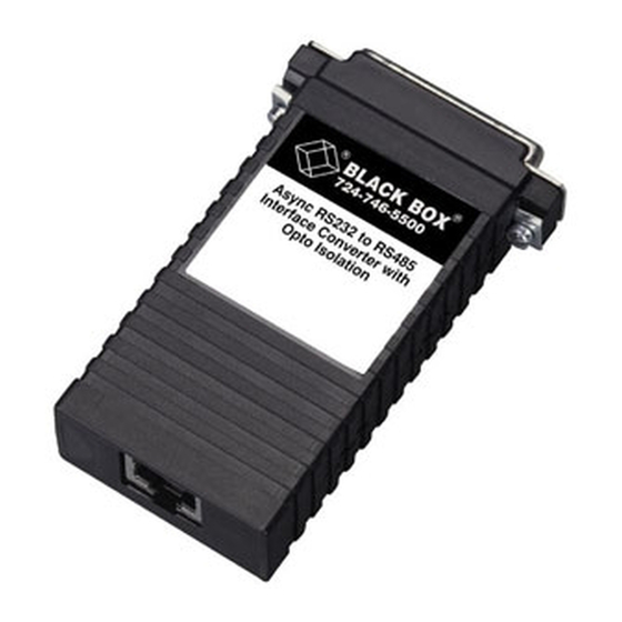
Async RS-232 to 2-Wire
CUSTOMER SUPPORT INFORMATION
Order toll-free in the U.S. 24 hours, 7 A.M. Monday to midnight Friday: 877-877-BBOX
FREE technical support, 24 hours a day, 7 days a week: Call 724-746-5500 or fax 724-746-0746
Mail order: Black Box Corporation, 1000 Park Drive, Lawrence, PA 15055-1018
Web site: www.blackbox.com • E-mail: info@blackbox.com
RS-485 Converter
APRIL 1999
IC520A-F
IC520A-M
IC521A-F
IC521A-M
Advertisement
Table of Contents

Related Manuals for Black Box IC520A-F


Summary of Contents for Black Box IC520A-F
- Page 1 Order toll-free in the U.S. 24 hours, 7 A.M. Monday to midnight Friday: 877-877-BBOX FREE technical support, 24 hours a day, 7 days a week: Call 724-746-5500 or fax 724-746-0746 Mail order: Black Box Corporation, 1000 Park Drive, Lawrence, PA 15055-1018 Web site: www.blackbox.com • E-mail: info@blackbox.com...
- Page 2 ASYNC RS-232 TO 2-WIRE RS-485 CONVERTER FEDERAL COMMUNICATIONS COMMISSION INDUSTRY CANADA RADIO FREQUENCY INTERFERENCE STATEMENTS This equipment generates, uses, and can radiate radio frequency energy and if not installed and used properly, that is, in strict accordance with the manufacturer’s instructions, may cause interference to radio communication. It has been tested and found to comply with the limits for a Class A computing device in accordance with the specifications in Subpart J of Part 15 of FCC rules, which are designed to provide reasonable protection against such interference...
- Page 3 ASYNC RS-232 TO 2-WIRE RS-485 CONVERTER NORMAS OFICIALES MEXICANAS (NOM) ELECTRICAL SAFETY STATEMENT INSTRUCCIONES DE SEGURIDAD 1. Todas las instrucciones de seguridad y operación deberán ser leídas antes de que el aparato eléctrico sea operado. 2. Las instrucciones de seguridad y operación deberán ser guardadas para referencia futura.
- Page 4 ASYNC RS-232 TO 2-WIRE RS-485 CONVERTER 10. El equipo eléctrico deber ser situado fuera del alcance de fuentes de calor como radiadores, registros de calor, estufas u otros aparatos (incluyendo amplificadores) que producen calor. 11. El aparato eléctrico deberá ser connectado a una fuente de poder sólo del tipo descrito en el instructivo de operación, o como se indique en el aparato.
- Page 5 ASYNC RS-232 TO 2-WIRE RS-485 CONVERTER TRADEMARKS The trademarks mentioned in this manual are the sole property of their owners.
-
Page 6: Table Of Contents
ASYNC RS-232 TO 2-WIRE RS-485 CONVERTER CONTENTS 1. Specifications ....... . 6 2. -
Page 7: Specifications
Data Rate — Up to 115,200 bps Distance — Up to 4000 feet (1219.2 m) on Category 5 solid cable Connectors — IC520A-F: (1) DB25 female, (1) 4-screw terminal block; IC520A-M: (1) DB25 male, (1) 4-screw terminal block; IC521A-F: (1) DB25 female, (1) RJ-45 female;... - Page 8 ASYNC RS-232 TO 2-WIRE RS-485 CONVERTER Power — Draws operating power from RS-232 data and control signals; no AC power or batteries required Size — 0.7"H x 2.1"W x 2.7"D (1.7 x 5.3 x 6.9 cm) Weight — 0.1 lb. (0.06 kg)
-
Page 9: Introduction
ASYNC RS-232 TO 2-WIRE RS-485 CONVERTER 2. Introduction 2.1 Description The Async RS-232 to 2-Wire RS-485 Converter provides excellent versatility in a compact package. Requiring no AC power or batteries for operation, the Converter supports asynchronous RS-232 data rates to 115.2 kbps over one unconditioned twisted pair in half-duplex mode. -
Page 10: Features
ASYNC RS-232 TO 2-WIRE RS-485 CONVERTER 2.2 Features • Operates asynchronously, half-duplex, point-to-point over two wires • Data rates to 115.2 kbps • No AC power or batteries are required • Compact size • Twisted-pair connection via screw terminals or RJ-45 •... -
Page 11: Configuration
ASYNC RS-232 TO 2-WIRE RS-485 CONVERTER 3. Configuration The Converter requires no configuration. It’s factory- configured as Data Communication Equipment (DCE). It connects to Data Terminal Equipment (DTE) via its DB25 RS-232 port. Figure 3-1 shows the RS-232 DB25 connector and terminal blocks on the printed circuit board. -
Page 12: Installation
50 feet (15.2 m). If your DTE equipment uses a DB9 connector, use one of the two following Black Box DB9 to DB25 adapters: FA520A-R2 (DB9 female to DB25 male) or FA521A (DB9 male to DB25 female). -
Page 13: Connection To The Rs-485 Interface
ASYNC RS-232 TO 2-WIRE RS-485 CONVERTER 4.2 Connection to the RS-485 Interface To function properly, the Converter must have one twisted pair of metallic wire. This pair must be “dry” (unconditioned) metallic wire, solid conductor, unshielded twisted pair, between 19 and 26 AWG (the higher-numbered gauges may limit distance somewhat). - Page 14 ASYNC RS-232 TO 2-WIRE RS-485 CONVERTER (no connection) Ground (no connection) (TX Data + [XMT+]) (TX Data - [XMT-]) (no connection) (Ground) (no connection) Figure 4-1. RJ-45 Interface for the Twisted Pair Line. Figure 4-2. Orientation of the RJ Connector.
-
Page 15: Connecting Via The Terminal Block
ASYNC RS-232 TO 2-WIRE RS-485 CONVERTER When connecting the twisted-pair cable from the Converter’s RJ-45 jack to the RS-485 device, your cable must be connected as shown in Table 4-1. Table 4-1. Connecting the Twisted Pair to the RS-485 Device. Converter RS-485 Device Signal... - Page 16 ASYNC RS-232 TO 2-WIRE RS-485 CONVERTER Figure 4-2. Stripping the Outer Insulation. 3. Strip back the insulation on each of the two twisted pair wires about 0.25". Figure 4-3. Strip the insulation on each of the two twisted pair wires. 4.
- Page 17 ASYNC RS-232 TO 2-WIRE RS-485 CONVERTER 5. Connect the same pair of wires to XMT A and XMT B on the RS-485 device, respectively, as shown in Table 4-2. Table 4-2. Crossover Cable Connection. Converter RS-485 Device XMT+ - - - - - - - - - - - - - - - XMT A XMT- - - - - - - - - - - - - - - - - XMT B 6.
- Page 18 ASYNC RS-232 TO 2-WIRE RS-485 CONVERTER Figure 4-4. Inserting the strain-relief assembly. 8. Bend the top half of the case as necessary to place it over the strain-relief assembly. Do not snap the case together yet. Figure 4-5. Placing the top half of the case over the strain-relief assembly.
- Page 19 ASYNC RS-232 TO 2-WIRE RS-485 CONVERTER 9. Insert one captive screw through a saddle washer and then insert the captive screw with the washer on it through the hole in the DB25 end of the case. Snap that side of the case closed. Repeat the process for the other side.
-
Page 20: Operation
ASYNC RS-232 TO 2-WIRE RS-485 CONVERTER 5. Operation Once the Converter is properly installed, it should operate transparently—as if it were a standard cable connection. The Converter derives operating power from the RS-232 data and control signals; there is no ON/OFF switch. -
Page 21: Appendix: Rs-232 Pin Configuration And Dce Connection Wiring
ASYNC RS-232 TO 2-WIRE RS-485 CONVERTER ASYNC RS-232 TO 2-WIRE RS-485 CONVERTER Appendix: RS-232 Pin Configuration and DCE Connection Wiring 1-(FG) Frame Ground 2-(TD) Transmit Data (Input) 3-(RD) Receive Data (Output) 4-(RTS) Request to Send (Input) 5-(CTS) Clear to Send (Output) 6-(DSR) Data Set Ready (Output) 7-(SG) Signal Ground (Input) Data... - Page 22 ASYNC RS-232 TO 2-WIRE RS-485 CONVERTER Table A-1. Direction of the RS-232 Signals. Pin Number Signal Name Direction Frame Ground (FG) Transmit Data (TD) To Converter Receive Data (RD) From Converter Request to Send (RTS) To Converter Clear to Send (CTS) From Converter Data Set Ready (DSR) From Converter...
- Page 23 © Copyright 1999. Black Box Corporation. All rights reserved. 1000 Park Drive • Lawrence, PA 15055-1018 • 724-746-5500 • Fax 724-746-0746...
Need help?
Do you have a question about the IC520A-F and is the answer not in the manual?
Questions and answers