LanParty Blood-Iron P45 Elite Series User Manual
System board
Hide thumbs
Also See for Blood-Iron P45 Elite Series:
- User manual (115 pages) ,
- User manual (152 pages) ,
- User manual (127 pages)
Table of Contents
Advertisement
Quick Links
Advertisement
Table of Contents

Related Manuals for LanParty Blood-Iron P45 Elite Series


Summary of Contents for LanParty Blood-Iron P45 Elite Series
- Page 1 System Board User’s Manual...
-
Page 2: Copyright
Copyright This publication contains information that is protected by copyright. No part of it may be reproduced in any form or by any means or used to make any transfor- mation/adaptation without the prior written permission from the copyright hold- ers. -
Page 3: Fcc And Doc Statement On Class B
FCC and DOC Statement on Class B This equipment has been tested and found to comply with the limits for a Class B digital device, pursuant to Part 15 of the FCC rules. These limits are designed to provide reasonable protection against harmful interference when the equipment is operated in a residential installation. -
Page 4: Table Of Contents
Table of Contents Copyright ................... 2 Trademarks ..................2 FCC and DOC Statement on Class B ..........3 Warranty ..................7 Static Electricity Precautions ............. 8 Safety Measures ................. 8 About the Package ................9 Before Using the System Board ............ - Page 5 PCI Express Slots ..............43 Download Flash BIOS Connector ..........43 Chapter 3 - BIOS Setup ..............44 Switchable Modes for Overclocking ..........44 Easy Mode ................44 Advance Mode ................ 44 Award BIOS Setup Utility .............. 45 Standard CMOS Features ............46 Advanced BIOS Features ............
- Page 6 Introduction Step 4: Install the RAID Driver During OS Installation ....115 Step 5: Install the Intel Matrix Storage Manager ....... 116 Appendix A - ABS: Auto Boost System ......... 118 Installing ABS ................118 The ABS Utility ................121 Appendix B - Troubleshooting ............
-
Page 7: Warranty
Introduction Warranty 1. Warranty does not cover damages or failures that arised from misuse of the product, inability to use the product, unauthorized replacement or alteration of components and product specifications. 2. The warranty is void if the product has been subjected to physical abuse, improper installation, modification, accidents or unauthorized repair of the product. -
Page 8: Static Electricity Precautions
Introduction Static Electricity Precautions It is quite easy to inadvertently damage your PC, system board, components or devices even before installing them in your system unit. Static electrical dis- charge can damage computer components without causing any signs of physical damage. -
Page 9: About The Package
Introduction About the Package The system board package contains the following items. If any of these items are missing or damaged, please contact your dealer or sales representative for as- sistance. One system board One IDE cable Two Serial ATA data cables ... -
Page 10: Chapter 1 - Introduction
Introduction Chapter 1 - Introduction Specifications Processor • LGA 775 socket for: - Intel Core 2 Quad and Intel Core 2 Duo ® ® • Supports Intel Enhanced Memory 64 Technology (EMT64T) • Supports Enhanced Intel SpeedStep Technology (EIST) • Supports Intel Hyper-Threading Technology • Supports 1333/1066/800MHz FSB Chipset • Intel chipset ® - Northbridge: Intel P45 Express chipset ® Intel Fast Memory Access technology ®... - Page 11 Introduction • 1 mini-DIN-6 PS/2 mouse port Rear Panel I/O • 1 mini-DIN-6 PS/2 keyboard port • 1 optical S/PDIF-out port • 1 coaxial RCA S/PDIF-out port • 6 USB 2.0/1.1 ports • 1 RJ45 LAN port • Center/subwoofer, rear R/L and side R/L jacks • Line-in, line-out (front R/L) and mic-in jacks Internal I/O • 3 connectors for 6 additional external USB 2.0 ports • 1 connector for an external COM port • 1 front audio connector • 1 CD-in connector • 1 IrDA connector • 6 Serial ATA connectors • 1 40-pin IDE connector • 1 floppy connector • 1 24-pin ATX power connector • 1 8-pin 12V power connector • 1 front panel connector • 4 fan connectors • 1 download flash BIOS connector • ACPI and OS Directed Power Management Power Management • ACPI STR (Suspend to RAM) function • Wake-On-PS/2 Keyboard/Mouse • Wake-On-USB Keyboard/Mouse • Wake-On-LAN • Wake-On-Ring • RTC timer to power-on the system • AC power failure recovery Hardware • Monitors CPU/system/Northbridge temperature and over- heat alarm Monitor • Monitors Vcore/Vdimm/Vnb/VCC5/12V/V5sb/Vbat voltages...
-
Page 12: Features
Introduction Features DDR2 DDR2 is a higher performance DDR technology whose data transfer rate delivers bandwidth of 4.3 GB per second and beyond. That is twice the speed of the con- ventional DDR without increasing its power consumption. DDR2 SDRAM modules work at 1.8V supply compared to 2.6V memory voltage for DDR modules. DDR2 also incorporates new innovations such as the On-Die Termination (ODT) as well as larger 4-bit pre-fetch against DDR which fetches 2 bits per clock cycle. - Page 13 Introduction CMOS Reloaded CMOS Reloaded is a technology that allows storing multiple user-defined BIOS settings by using the BIOS utility to save, load and name the settings. This is especially useful to overclockers who require saving a variety of overclocked set- tings and being able to conveniently switch between these settings simultane- ously.
-
Page 14: Chapter 2 - Hardware Installation
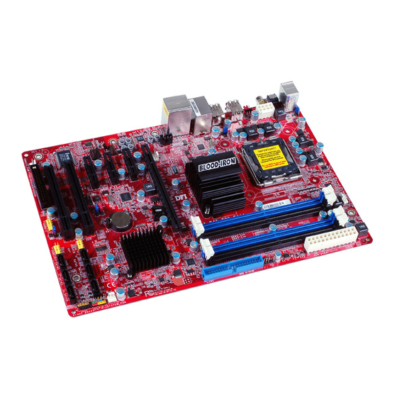
Hardware Installation Chapter 2 - Hardware Installation System Board Layout PS/2 power select (JP7) Mouse CPU fan DDR2-2 DDR2-4 Optical DDR2-3 S/PDIF-out DDR2-1 Coaxial RCA C217 S/PDIF-out Clear CMOS (JP8) USB 9 USB 8 power USB 6-11 power select (JP5) USB 11 USB 10 USB 7... -
Page 15: System Memory
Hardware Installation Important: Electrostatic discharge (ESD) can damage your system board, processor, disk drives, add-in boards, and other components. Perform the upgrade instruction procedures described at an ESD workstation only. If such a station is not available, you can provide some ESD protection by wearing an antistatic wrist strap and attaching it to a metal part of the system chassis. - Page 16 Hardware Installation The system board supports the following memory interface. Single Channel (SC) Data will be accessed in chunks of 64 bits (8B) from the memory channels. Virtual Single Channel (VSC) If both channels are populated with different memory configurations, the MCH defaults to Virtual Single Channel.
-
Page 17: Hardware Installation
Hardware Installation The table below lists the various optimal operating modes that should be config- ured for the memory channel operation. Config DIMM 4 DIMM 1 DIMM 2 DIMM 3 No memory Single channel A Single channel A Single channel A Single channel B Single channel B Single channel B... -
Page 18: Installing The Dim Module
Hardware Installation Installing the DIM Module Note: The system board used in the following illustrations may not resemble the actual board. These illustrations are for reference only. 1. Make sure the PC and all other peripheral devices connected to it has been powered down. - Page 19 Hardware Installation 6. Grasping the module by its edges, position the module above the socket with the “notch” in the module aligned with the “key” on the socket. The keying mechanism ensures the module can be plugged into the socket in only one way.
-
Page 20: Cpu
Hardware Installation The system board is equipped with a surface mount LGA 775 socket. This socket is exclusively designed for installing a LGA 775 packaged Intel CPU. Important: 1. Before you proceed, make sure (1) the LGA775 socket comes with a protective cap, (2) the cap is not damaged and (3) the socket’s con- tact pins are not bent. - Page 21 Hardware Installation 4. The CPU socket comes with a removable protec- tive cap. The cap is used to protect the CPU socket Protective cap against dust and harm- ful particles. Remove the protective cap only when you are about to install the CPU.
- Page 22 Hardware Installation 8. Position the CPU above the socket. The gold mark on the CPU must align with pin 1 of the CPU socket. Important: Handle the CPU by its edg- es and avoid touching the pins. Pin 1 of the socket Gold mark 9.
- Page 23 Hardware Installation 10. Close the load plate. Load plate 11. Push the load lever down to lock the socket. The lever should hook onto the retention tab to indicate that the CPU is completely secured in the socket. Retention tab Load lever...
-
Page 24: Installing The Fan And Heat Sink
Hardware Installation Installing the Fan and Heat Sink The CPU must be kept cool by using a CPU fan with heat sink. Without sufficient air circulation across the CPU and heat sink, the CPU will overheat damaging both the CPU and system board. Note: A boxed Intel processor already includes the CPU fan and heat sink as-... - Page 25 Hardware Installation 4. Rotate each push-pin ac- cording to the direction of the arrow shown on top of the pin. Push down two pushpins that are diagonally across the heat sink. Perform the same procedure for the other two push-pins. Push pin Heat sink 5.
-
Page 26: Northbridge Heat Sink
Hardware Installation Northbridge Heat Sink The Northbridge must be kept cool by using a heat sink. The heat sink will dis- sipate heat generated by the Northbridge. Without the heat sink, the Northbridge will overheat damaging both the Northbridge and the system board. -
Page 27: Jumper Settings
Hardware Installation Jumper Settings Clear CMOS Data C217 1-2 On: Normal (default) 1-2 On: Normal (default) 2-3 On: Clear CMOS Data 2-3 On: Clear CMOS Data If you encounter the following, a) CMOS data becomes corrupted. b) You forgot the supervisor or user password. c) The overclocked settings in the BIOS resulted to the system’s instability or caused system boot up problems. -
Page 28: Ps/2 Power Select
Hardware Installation PS/2 Power Select 1-2 On: 5V 2-3 On: 5VSB C217 (default) Selecting 5VSB will allow you to use the PS/2 keyboard or PS/2 mouse to wake up the system. Important: The 5VSB power source of your power supply must support ≥720mA. -
Page 29: Usb Power Select
Hardware Installation USB Power Select C217 USB 6-11 (JP5) 1-2 On: 5V 2-3 On: 5VSB (default) USB 0-5 (JP6) 1-2 On: 5V 2-3 On: 5VSB (default) Selecting 5VSB will allow you to use the USB keyboard or USB mouse to wake up the system. -
Page 30: Secondary Rtc Reset
Hardware Installation Secondary RTC Reset C217 JP12 1-2 On: Normal 2-3 On: RTC Reset (default) When the RTC battery is removed, this jumper resets the manageability register bits in the RTC. Note: 1. The SRTCRST# input must always be high when all other RTC power planes are on. -
Page 31: Ps/2 Ports And S/Pdif Ports
Hardware Installation PS/2 Ports and S/PDIF Ports PS/2 Mouse C217 PS/2 KB Optical S/PDIF Coaxial RCA S/PDIF PS/2 Mouse and PS/2 Keyboard Ports These ports are used to connect a PS/2 mouse and a PS/2 keyboard. Optical S/PDIF The optical S/PDIF jack is used to connect an external audio output device using an optical S/PDIF cable. -
Page 32: Usb And Lan Ports
Hardware Installation USB and LAN Ports USB 9 USB 8 C217 USB 11 USB 10 USB 7 USB 6 USB 4-5 USB 2-3 USB 0-1 The USB ports are used to connect USB 2.0/1.1 devices. The 10-pin connectors allow you to connect 6 additional USB 2.0/1.1 ports. Your USB ports may come mounted on a card-edge bracket. -
Page 33: Audio And Cd-In
Hardware Installation Audio and CD-In Rear audio C217 Center/ Line-in Subwoofer Front R/L Rear R/L Mic-in Side R/L Front audio Right audio channel Ground CD-in Ground Left audio channel Rear Panel Audio • Center/Subwoofer Jack (Orange) This jack is used to connect to the center and subwoofer speakers of the au- dio system. -
Page 34: Internal I/O Connectors
Hardware Installation Front Audio The front audio connector is used to connect to the line-out and mic-in jacks that are at the front panel of your system. CD-in The CD-in connector is used to receive audio from a CD-ROM drive, TV tuner or MPEG card. -
Page 35: Fdd Connector And Ide Connector
Hardware Installation FDD Connector and IDE Connector C217 FDD Connector The floppy disk drive connector is used to connect a floppy drive. Insert one end of the floppy cable into this connector and the other end-most connector to the floppy drive. The colored edge of the cable should align with pin 1 of this con- nector. -
Page 36: Irda And Com (Serial) Connectors
Hardware Installation IrDA and COM (Serial) Connectors C217 IRRX N. C. Ground IRTX IrDA 1 IrDA Connect the cable connector from your IrDA module to the IrDA connector. Note: The sequence of the pin functions on some IrDA cable may be reversed from the pin function defined on the system board. -
Page 37: Cooling Fan Connectors
Hardware Installation Cooling Fan Connectors CPU fan C217 Ground Speed Control Power Sense NB fan Sense Ground System fan Power Ground Power Chassis fan Sense Sense Ground Power These fan connectors are used to connect cooling fans. Cooling fans will provide adequate airflow throughout the chassis to prevent overheating the CPU and sys- tem board components. -
Page 38: Leds
Hardware Installation LEDs C217 DRAM Power LED Standby Power LED DRAM Power LED This LED will light when the system’s power is on. Standby Power LED This LED will light when the system is in the standby mode. Important: When the DRAM Power LED and/or Standby Power LED lit red, it indi- cates that power is present on the DIMM sockets and/or PCI slots. -
Page 39: Power Connectors
Hardware Installation Power Connectors Use a power supply that complies with the ATX12V Power Supply Design Guide Version 1.1. An ATX12V power supply unit has a standard 24-pin ATX main power connector that must be inserted into this connector. 12 24 +3.3VDC C217 +5VDC... - Page 40 Hardware Installation The power connectors from the power supply unit are designed to fit the 24-pin and 8-pin connectors in only one orientation. Make sure to find the proper orien- tation before plugging the connectors. The system board requires a minimum of 300 Watt power supply to operate. Your system configuration (CPU power, amount of memory, add-in cards, peripherals, etc.) may exceed the minimum power requirement.
-
Page 41: Front Panel Connectors
Hardware Installation Front Panel Connectors C217 PWR-LED HD-LED RESET ATX-SW SPEAKER 19 20 HD-LED: Primary/Secondary IDE LED This LED will light when the hard drive is being accessed. RESET: Reset Switch This switch allows you to reboot without having to power off the system thus prolonging the life of the power supply or system. - Page 42 Hardware Installation PWR-LED: Power/Standby LED When the system’s power is on, this LED will light. When the system is in the S1 (POS - Power On Suspend) or S3 (STR - Suspend To RAM) state, it will blink every second. Note: If a system did not boot-up and the Power/Standby LED did not light af- ter it was powered-on, it may indicate that the CPU or memory module...
-
Page 43: Pci Express Slots
Hardware Installation PCI Express Slots C217 PCI Express x16 PCI Express x1 PCI Express x1 PCI Express x1 Download Flash BIOS Connector C217... -
Page 44: Chapter 3 - Bios Setup
BIOS Setup Chapter 3 - BIOS Setup Switchable Modes for Overclocking Aimed to provide convenience and superb overclockability, the Genie BIOS Set- ting submenu comes available in Easy mode (default mode) and Advance mode. Easy Mode Easy mode displays fields commonly used by users. Advance Mode If you intend to tweak your PC or boost its overclock feature, you can switch the Genie BIOS Setting submenu from Easy mode to Advance mode by simply... -
Page 45: Award Bios Setup Utility
BIOS Setup Award BIOS Setup Utility The Basic Input/Output System (BIOS) is a program that takes care of the ba- sic level of communication between the processor and peripherals. In addition, the BIOS also contains codes for various advanced features found in this system board. -
Page 46: Standard Cmos Features
BIOS Setup Standard CMOS Features Use the arrow keys to highlight “Standard CMOS Features” then press <Enter>. A screen similar to the one below will appear. Phoenix - AwardBIOS CMOS Setup Utility Standard CMOS Features Date <mm:dd:yy> Thu, Jun 11 2009 Item Help Time <hh:mm:ss>... - Page 47 BIOS Setup IDE Channel 0 Master to IDE Channel 4 Slave These fields are used to configure Parallel ATA drives. Move the cursor to a field then press <Enter>. The following screen will appear. Phoenix - AwardBIOS CMOS Setup Utility IDE Channel 0 Master Press Enter Item Help...
- Page 48 BIOS Setup Head This field displays the number of read/write heads. Precomp This field displays the number of cylinders at which to change the write tim- ing. Landing Zone This field displays the number of cylinders specified as the landing zone for the read/write heads.
- Page 49 BIOS Setup Halt On This field determines whether the system will stop if an error is detected during power up. The default setting is All Errors. No Errors The system boot will not stop for any errors detected. All Errors The system boot will stop whenever the BIOS detects a non-fatal error.
-
Page 50: Advanced Bios Features
BIOS Setup Advanced BIOS Features The Advanced BIOS Features allows you to configure your system for basic op- eration. Some entries are defaults required by the system board, while others, if enabled, will improve the performance of your system or let you set some fea- tures according to your preference. - Page 51 BIOS Setup Quick Power On Self Test This field speeds up Power On Self Test (POST) whenever the system is powered on. The BIOS will shorten or skip some check items during POST. To attain the shortest POST time, select “Fast”. First Boot Device, Second Boot Device, Third Boot Device and Boot Other Device Select the drive to boot first, second and third in the “First Boot Device”...
- Page 52 BIOS Setup Typematic Rate (Chars/Sec) This field allows you to select the rate at which the keys are accelerated. Typematic Delay (Msec) This field allows you to select the delay between when the key was first de- pressed and when the acceleration begins. Security Option This field determines when the system will prompt for the password- everytime the system boots or only when you enter the BIOS setup.
-
Page 53: Bios Setup
BIOS Setup Hard Disk Boot Priority This field is used to select the boot sequence of the hard drives. Move the cursor to this field then press <Enter>. Use the Up or Down arrow keys to select a de- vice then press <+> to move it up or <-> to move it down the list. Phoenix - AwardBIOS CMOS Setup Utility Hard Disk Boot Priority 1. -
Page 54: Advanced Chipset Features
BIOS Setup Advanced Chipset Features Phoenix - AwardBIOS CMOS Setup Utility Advanced Chipset Features Enabled System BIOS Cacheable Item Help Disabled Memory Hole at 15M-16M Menu Level PCI Express Root Port Func Press Enter VT-d Disabled Close by CAS# LT Slow Slow : Move... - Page 55 BIOS Setup PCI Express Root Port Func Move the cursor to this field and press <Enter>. The following screen will appear. Phoenix - AwardBIOS CMOS Setup Utility PCI Express Root Port Func v1.0a PCI-E Compliancy Mode Item Help Menu Level ...
-
Page 56: Integrated Peripherals
BIOS Setup Integrated Peripherals Phoenix - AwardBIOS CMOS Setup Utility Integrated Peripherals Item Help Press Enter OnChip IDE Device Press Enter Onboard Device Menu Level Press Enter SuperIO Device Press Enter USB Device Setting : Move Enter: Select +/-/PU/PD: Value F10: Save... - Page 57 BIOS Setup SATA Mode This field is used to configure the SATA devices supported by the south- bridge. This option configures the Serial ATA drives as Parallel ATA storage devices. RAID This option allows you to create RAID or Intel Matrix Storage configuration on Serial ATA devices.
-
Page 58: Super Io Device
BIOS Setup Super IO Device Phoenix - AwardBIOS CMOS Setup Utility SuperIO Device Power On By Mouse Disabled Item Help Power On By Keyboard Disabled Menu Level x Power On By Button Enabled Enter x KB Power On Password x Hot Key Power On Ctrl-F1 Onboard FDC Controller... - Page 59 BIOS Setup KB Power On Password Move the cursor to this field and press <Enter>. Enter your password. You can enter up to 5 characters. Type in exactly the same password to confirm, then press <Enter>. The power button will not function once a keyboard password has been set in this field.
-
Page 60: Usb Device Setting
BIOS Setup PWRON After PWR-Fail When power returns after an AC power failure, the system’s power is off. You must press the Power button to power-on the system. When power returns after an AC power failure, the system will automatically power-on. - Page 61 BIOS Setup USB Operation Mode High Speed If the USB device is a high speed device, it will operate in high speed mode. If it is a full/low speed device, it will operate in full/low speed mode. Full/Low Speed Regardless of the speed of the USB device, it will always operate in full/low speed mode.
-
Page 62: Power Management Setup
BIOS Setup Power Management Setup The Power Management Setup allows you to configure your system to most ef- fectively save energy. Phoenix - AwardBIOS CMOS Setup Utility Power Management Setup PCI Express PM Function Press Enter Item Help Enabled ACPI Function Menu Level S3(STR) -
Page 63: Pci Express Pm Function
BIOS Setup PCI Express PM Function This field is used to configure the PCI Express PM function. Phoenix - AwardBIOS CMOS Setup Utility PCI Express PM Function PEG Port ASPM Disabled Item Help Root Port ASPM Disabled Menu Level DMI Port ASPM Disabled ... - Page 64 BIOS Setup Run VGABIOS if S3 Resume When this field is set to Auto, the system will initialize the VGA BIOS when it wakes up from the S3 state. This can be configured only if the “ACPI Suspend Type” field is set to “S3(STR)”. When this feature is disabled, the system resume time is shortened but system will need an AGP driver to initialize the VGA card.
- Page 65 BIOS Setup Suspend Mode This is configurable only when the Power Management field is set to “User De- fine”. When the system enters the power saving time set in this field, the CPU and onboard peripherals will be shut off. HDD Power Down This is configurable only when the Power Management field is set to User Define.
- Page 66 BIOS Setup Date (of Month) Alarm The system will power-on everyday according to the time set in the “Time (hh:mm:ss) Alarm” field. 1-31 Select a date you would like the system to power-on. The system will power- on on the set date, and time set in the “Time (hh:mm:ss) Alarm” field. Time (hh:mm:ss) of Alarm This is used to set the time you would like the system to power-on.
-
Page 67: Pnp/Pci Configurations
BIOS Setup PnP/PCI Configurations This section describes configuring the PCI bus system. It covers some very tech- nical items and it is strongly recommended that only experienced users should make any changes to the default settings. Phoenix - AwardBIOS CMOS Setup Utility PnP/PCI Configurations Init Display First PCI Slot... -
Page 68: Irq Resources
BIOS Setup IRQ Resources Move the cursor to this field and press <Enter>. This field is used to set each system interrupt to either Reserved or PCI Device. Phoenix - AwardBIOS CMOS Setup Utility IRQ Resources IRQ-3 assigned to PCI Device Item Help IRQ-4 assigned to PCI Device... -
Page 69: Pc Health Status
BIOS Setup PC Health Status Phoenix - AwardBIOS CMOS Setup Utility PC Health Status Shutdown Temperature Disabled Item Help Adjust CPU Temp Default Menu Level CPUFan Fully ON If CPUTemp > 50 CPUFan Turn OFF If CPUTemp < 25 CPU Core Voltage 1.18V... - Page 70 BIOS Setup Note: 1. If the CPU temperature runs between the highest (set in the “CPUFan Fully On If CPUTemp” field) and lowest (set in the “CPUFan Turn Off If CPUTemp” field) temperature, the system will automatically adjust the CPU fan’s speed according to the temperature. 2.
-
Page 71: Genie Bios Setting
BIOS Setup Genie BIOS Setting Aimed to provide convenience and superb overclockability, this submenu comes available in Easy mode (default mode) and Advance mode. Easy Mode Easy mode displays fields commonly used by users. Advance Mode If you intend to tweak your PC or boost its overclock features, you can switch the Genie BIOS Setting submenu from Easy mode to Advance mode by simply pressing <F9>... -
Page 72: Cpu Feature
BIOS Setup Phoenix - AwardBIOS CMOS Setup Utility Genie BIOS Setting Item Help Press Enter CPU Feature Press Enter DRAM Timing Menu Level Press Enter Voltage Setting Mode 2 Exit Setup Shutdown Enabled Shutdown After AC Loss Enabled AC ShutDown Free O.C Fail Retry Counter... - Page 73 BIOS Setup CPU N/2 Ratio The options are Enabled and Disabled. Target CPU Clock This field will show the targeted CPU clock. CPU Clock This field provides several options for selecting the external system bus clock of the processor. The available options allow you to adjust the processor’s bus clock by 1MHz increment.
- Page 74 BIOS Setup CPU Feature Move the cursor to this field and press <Enter>, the following screen will appear: Phoenix - AwardBIOS CMOS Setup Utility CPU Feature Thermal Management Control Enabled Item Help PPM(EIST) Mode Enabled Menu Level Limit CPUID MaxVal Disabled ...
-
Page 75: Dram Timing
BIOS Setup Core Multi-Processing The options are Enabled and Disabled. DRAM Timing Move the cursor to this field and press <Enter>. The following screen will appear. Phoenix - AwardBIOS CMOS Setup Utility DRAM Timing Item Help Auto Enhance Data Transmitting Enhance Addressing Auto Menu Level... - Page 76 BIOS Setup CAS Latency Time (tCL) This field is used to select the clock cycle of the CAS latency time. The op- tion selected specifies the timing delay before SDRAM starts a read command after receiving it. RAS# to CAS# Delay (tRCD) This field is used to select the RAS# to CAS# delay time when reading and writing to the same bank.
- Page 77 BIOS Setup Ranks Write to Write (tWRWR) The options are 0 to 15. Ranks Write to Read (tWRRD) The options are 0 to 15. Read CAS# Precharge (tRTP) The options are Auto, and 1 to 15. ALL PRE to Refresh The options are Auto, and 1 to 7.
- Page 78 BIOS Setup DLL and RECOMP Settings This field is used to configure the DLL and RECOMP settings. The options are Auto and By Menu. CH1 DRAM Default Skew and CH2 DRAM Default Skew These fields are used to select the DRAM’s default skew. The options are Model 0 to Model 7.
- Page 79 BIOS Setup Ch2 Command to CS Delay The options are Auto, 1CLK to 7CLK. Read Delay Phase Adjust Move the cursor to this field and press <Enter>. The following screen will ap- pear. Phoenix - AwardBIOS CMOS Setup Utility Read Delay Phase Adjust Item Help 7-7-7-7-7 Ch1 Read delay phase (4~0)
- Page 80 BIOS Setup Voltage Setting Move the cursor to this field and press <Enter>. The following screen will appear. Phoenix - AwardBIOS CMOS Setup Utility Voltage Setting Item Help Auto CPU VID Special Add DRAM Voltage Control 1.908 Menu Level SB Core/CPU PLL Voltage 1.55V ...
- Page 81 BIOS Setup Clockgen Voltage Control This field is used to select the clock generator’s voltage. CPU GTL 0/2 REF Volt and CPU GTL 1/3 REF Volt These fields are used to configure the CPU GTL REF voltage. The options are 0.6075 to 0.7025.
-
Page 82: Cmos Reloaded
BIOS Setup CMOS Reloaded The CMOS Reloaded submenu allows you to save different configurations and when needed, allows you to conveniently restore one of these previously saved configurations. Highlight CMOS Reloaded in the main menu then press <Enter>. Phoenix - AwardBIOS CMOS Setup Utility CMOS Reloaded Item Help Auto Save Bootable Setting... - Page 83 BIOS Setup Auto Save Bootable Setting This field is used to automatically save the last bootable setting from CMOS to an area in the SEEPROM referred to as the backup bank. To use this function: 1. Set this field to Enabled. 2.
- Page 84 BIOS Setup User Defined Setting Bank #1/2/3/4 Bank Description To name the BIOS setting, move the cursor to “Bank Description” then press <Enter>. You can enter up to 60 characters. Providing a name to the BIOS setting will allow you to easily remember the settings in the bank. Save to this Bank To save the BIOS setting, move the cursor to “Save to this Bank”...
-
Page 85: Load Optimized Defaults
BIOS Setup Load Optimized Defaults The “Load Optimized Defaults” option loads optimized settings from the BIOS ROM. Use the default values as standard values for your system. Highlight this option in the main menu and press <Enter>. Phoenix - AwardBIOS CMOS Setup Utility Genie BIOS Setting Standard CMOS Features ... -
Page 86: Set Supervisor Password
BIOS Setup Set Supervisor Password If you want to protect your system and setup from unauthorized entry, set a supervisor’s password with the “System” option selected in the Advanced BIOS Features. If you want to protect access to setup only, but not your system, set a supervisor’s password with the “Setup”... -
Page 87: Set User Password
BIOS Setup Set User Password If you want another user to have access only to your system but not to setup, set a user’s password with the “System” option selected in the Advanced BIOS Features. If you want a user to enter a password when trying to access setup, set a user’s password with the “Setup”... -
Page 88: Save & Exit Setup
BIOS Setup Save & Exit Setup When all the changes have been made, highlight “Save & Exit Setup” and press <Enter>. Phoenix - AwardBIOS CMOS Setup Utility Standard CMOS Features Genie BIOS Setting Advanced BIOS Features CMOS Reloaded ... -
Page 89: Exit Without Saving
BIOS Setup Exit Without Saving When you do not want to save the changes you have made, highlight “Exit With- out Saving” and press <Enter>. Phoenix - AwardBIOS CMOS Setup Utility Standard CMOS Features Genie BIOS Setting Advanced BIOS Features CMOS Reloaded ... -
Page 90: Raid Bios
BIOS Setup RAID BIOS (LP BI P45-T2RS Elite) The Intel RAID BIOS utility is used to configure and manage RAID on Serial ATA drives. When the system powers-up and all drives have been detected, the Intel RAID BIOS status message screen will appear. Press the <Ctrl> and <I> keys simul- taneously to enter the utility. -
Page 91: Updating The Bios
BIOS Setup Updating the BIOS To update the BIOS, you will need the new BIOS file and a flash utility, AWD- FLASH.EXE. You can download them from DFI’s web site or contact technical sup- port or your sales representative. 1. Save the new BIOS file along with the flash utility AWDFLASH.EXE to a floppy disk. -
Page 92: Chapter 4 - Supported Software
Supported Software Chapter 4 - Supported Software The DVD that came with the system board contains drivers, utilities and software applications required to enhance the performance of the system board. Insert the DVD into an optical drive. The screen shown below will appear. If after inserting the DVD, “Autorun”... -
Page 93: Intel Chipset Device Software
Supported Software Intel Chipset Device Software On the top row of the screen, click the 1st icon to open the Chipset Driver menu. 1. Click “Intel(R) Chipset De- vice Software”. 2. The setup program is now ready to install the utility. Click Next. - Page 94 Supported Software 3. Read the license agreement then click Yes. 4. Go through the readme document for system quirements and installation tips then click Next. 5. The setup program is now installing the driver. Click Next to continue.
- Page 95 Supported Software 6. Click “Yes, I want to start this computer now” then click Finish. Restarting the system will allow the new software in- stallation to take effect.
-
Page 96: Graphics Driver
Supported Software Graphics Driver On the top row of the screen, click the 2nd icon to open the Graphics Driver menu. The DVD provides both ATI and nVidia graphics drivers. Select the driver accord- ing to the graphics card that you are using. ATi Radeon Drivers 1. - Page 97 Supported Software 3. Select the language you like Catalyst Install Manager to display then click Next. 4. You are now ready to install the driver. Click Install.
- Page 98 Supported Software 5. Select the component (Ex- press or Custom) you want to install then click Next. 6. Read the license agree- ment then click Accept.
- Page 99 Supported Software 7. Click Yes to create the ATI Technologies folder. 8. Follow the remainder of the steps shown on the screen then restart the sys- tem to allow the new driver installation to take effect.
-
Page 100: Nvidia Gforce 8 Series Drivers
Supported Software nVidia GForce 8 Series Drivers 1. Click “nVidia GForce 8 Se- ries Drivers”. 2. Read the license agreement then click “I accept the terms in the license agree- ment”. Click Next. 3. Click Next to install to the destination folder or click Change to select another... - Page 101 Supported Software 4. The setup program will extract the files needed to install the driver on your computer. After all files have been extracted, click Next. 5. You are now ready to stall the driver. Click Next. 6. Click “Yes, I want to start my computer now”...
-
Page 102: Realtek Audio Drivers
Supported Software Realtek Audio Drivers On the top row of the screen, click the 3rd icon to open the Audio Driver menu. 1. Click “Realtek Audio Driv- ers”. 2. The setup program is now ready to install the driver. Click Next. 3. - Page 103 Supported Software 4. Click “Yes, I want to restart my computer now” then click Finish. Restarting the system will allow the new driver instal- lation to take effect.
-
Page 104: Jmc250 Lan Drivers
Supported Software JMC250 LAN Drivers On the top row of the screen, click the 4th icon to open the Network Driver menu. 1. Click “JMC250 LAN Drivers”. 2. Click Install to begin instal- lation. 3. The setup program is now installing the driver. - Page 105 Supported Software 4. Click Finish.
-
Page 106: Raid Floppy Driver
Supported Software RAID Floppy Driver On the top row of the screen, click the 5th icon to open the RAID Driver menu. 1. Click “RAID Floppy Driver”. 2. Windows Explorer will ap- pear showing the folder where the driver files are located in the DVD. -
Page 107: Smart Guardian
Supported Software Smart Guardian The Smart Guardian utility is capable of monitoring the system’s temperature, fan speed, voltage, etc. and allows you to manually set a range (Highest and Lowest Limit) to the items being monitored. If the settings/values are over or under the set range, a warning message will pop-up. - Page 108 Supported Software 3. Enter the necessary infor- mation then click Next. 4. Click Next to install to the designated folder or click Browse to select another folder. 5. Click Next to add the pro- gram icon to the Program Folder.
- Page 109 Supported Software 6. Select the option in ac- cordance to the operating system that you are using then click Next. 7. Click Finish. Reboot the system for the driver to take effect. 8. After rebooting the system, you will find the Smart Guardian icon displayed on the screen.
-
Page 110: Adobe Acrobat Reader 7.05
Supported Software Adobe Acrobat Reader 7.05 On the top row of the screen, click the last icon to open the Manuals menu. 1. Click “Adobe Acrobat Read- er 7.05”. 2. Click Next to continue. 3. Setup is now ready to in- stall. - Page 111 Supported Software 4. Click Next to install or click Change Destination Folder to select another folder. 5. Click Install to begin instal- lation. 6. Click Finish to exit instal- laion.
-
Page 112: Installation Notes
Supported Software Installation Notes 1. “Autorun” ONLY supports the Windows XP and Windows Vista operating ® ® systems. If after inserting the DVD, “Autorun” did not automatically start, please go directly to the root directory of the DVD and double-click “Setup”. 2. -
Page 113: Chapter 5 - Raid
RAID Chapter 5 - RAID (LP BI P45-T2RS Elite) The Intel ICH10R chip alows configuring RAID on Serial ATA drives. It supports RAID 0, RAID 1, RAID 0+1 and RAID 5. RAID Levels RAID 0 (Striped Disk Array without Fault Tolerance) RAID 0 uses two new identical hard disk drives to read and write data in parallel, interleaved stacks. -
Page 114: Settings
RAID Settings To enable the RAID function, the following settings are required. 1. Connect the Serial ATA drives. 2. Configure Serial ATA in the Award BIOS. 3. Configure RAID in the RAID BIOS. 4. Install the RAID driver during OS installation. 5. -
Page 115: Step 4: Install The Raid Driver During Os Installation
RAID Step 4: Install the RAID Driver During OS Installation The RAID driver must be installed during the Windows XP or Windows 2000 in- ® ® stallation using the F6 installation method. This is required in order to install the operating system onto a hard drive or RAID volume when in RAID mode or onto a hard drive when in AHCI mode. -
Page 116: Step 5: Install The Intel Matrix Storage Manager
RAID Step 5: Install the Intel Matrix Storage Manager The Intel Matrix Storage Manager can be installed from within Windows. It allows RAID volume management (create, delete, migrate) from within the operating system. It will also display useful SATA device and RAID volume information. The user interface, tray icon service and monitor service allow you to monitor the current status of the RAID volume and/or SATA drives. - Page 117 RAID 5. Read the warning carefully then click Next. 6. Read the license agree- ment then click Yes. 7. Go through the readme document to view system requirements and installa- tion information then click Next. 8. Follow the remainder of the steps shown on the screen; clicking “next” each time you finish a step.
-
Page 118: Appendix A - Abs: Auto Boost System
ABS - Auto Boost System Appendix A - ABS: Auto Boost System The ABS (Auto Boost System) technology provides the convenience of saving and loading several OC settings. It allows you to use the best OC setting to optimize your system’s performance. You can “Auto Boost”... - Page 119 ABS - Auto Boost System 3. The installation wizard is extracting the files needed to install the utility. The wizard will lead you to complete the installation. 4. Setup is now ready to stall the utility. Click Next. 5. Click Next to install to the destination folder or click Change to select another...
- Page 120 ABS - Auto Boost System 6. Click Install to begin the installation. 7. The installation wizard will copy all the necessary files and optimize the ABS fea- tures. 8. Click Finish to exit setup.
-
Page 121: The Abs Utility
ABS - Auto Boost System The ABS Utility 1. To run the ABS utility, power up your system then press F1. The screen will show the CPU upgrade in- formation. Press “Any Key” to continue. 2. When the system enters the operating system, the ABS utility will appear and display the system’s in-... - Page 122 ABS - Auto Boost System 5. Click Confirm. 6. ABS supports Win Reloaded and Auto Upgrade features. Click Auto Upgrade. 7. Click Backup. 8. The default settings will appear on the screen. Click Save.
- Page 123 ABS - Auto Boost System 9. Enter a name for the de- fault setting then click Save. You have just cre- ated a backup file of the board’s default setting. 10. If in any case a new OC setting causes system in- stability, you can always retrieve the backup file saved earlier by clicking...
- Page 124 ABS - Auto Boost System 12. Select the backup file then click Open. 13. Click Write to load Banks 1-4 into the BIOS. If you want the system to auto upgrade the setting the next time you boot the system, click “Enable Auto Upgrade Next Boot”.
- Page 125 ABS - Auto Boost System 14. Click Yes to reboot. Important: 1. We strongly recommend that you backup the default setting. If in any case your overclock setting causes system instability, you can always retrieve the default setting by reloading the backup file. 2. Everytime you change the BIOS settings, remember to always backup the file because the previous backup file will not match the new BIOS settings therefore it will not work.
-
Page 126: Appendix B - Troubleshooting
Troubleshooting Appendix B - Troubleshooting Troubleshooting Checklist This chapter of the manual is designed to help you with problems that you may encounter with your personal computer. To efficiently troubleshoot your system, treat each problem individually. This is to ensure an accurate diagnosis of the problem in case a problem has multiple causes. -
Page 127: Power Supply
Troubleshooting The picture seems to be constantly moving. 1. The monitor has lost its vertical sync. Adjust the monitor’s vertical sync. 2. Move away any objects, such as another monitor or fan, that may be creating a magnetic field around the display. 3. -
Page 128: Hard Drive
Troubleshooting Hard Drive Hard disk failure. 1. Make sure the correct drive type for the hard disk drive has been entered in the BIOS. 2. If the system is configured with two hard drives, make sure the bootable (first) hard drive is configured as Master and the second hard drive is config- ured as Slave. - Page 129 Troubleshooting System Board 1. Make sure the add-in card is seated securely in the expansion slot. If the add-in card is loose, power off the system, re-install the card and power up the system. 2. Check the jumper settings to ensure that the jumpers are properly set. 3.
-
Page 130: Appendix C - Debug Led Post And Troubleshooting
Debug LED POST and Troubleshooting Appendix C - Debug LED Post and Troubleshooting General Debug LED POST and Troubleshooting... - Page 131 Debug LED POST and Troubleshooting...
- Page 132 Debug LED POST and Troubleshooting...
- Page 133 Debug LED POST and Troubleshooting...
- Page 134 Debug LED POST and Troubleshooting Abnormal Debug LED POST and Troubleshooting...
Need help?
Do you have a question about the Blood-Iron P45 Elite Series and is the answer not in the manual?
Questions and answers