Table of Contents
Advertisement
Quick Links
Advertisement
Table of Contents

Related Manuals for LanParty UT 865PE-T


Summary of Contents for LanParty UT 865PE-T
- Page 1 System Board User’s Manual 82800429...
- Page 2 Copyright This publication contains information that is protected by copyright. No part of it may be reproduced in any form or by any means or used to make any transformation/adaptation without the prior written permission from the copyright holders. This publication is provided for informational purposes only. The manufacturer makes no representations or warranties with respect to the contents or use of this manual and specifically disclaims any express or implied warranties of merchantability or fitness for any...
-
Page 3: Fcc And Doc Statement On Class B
Battery: • Danger of explosion if battery incorrectly replaced. • Replace only with the same or equivalent type recommend by the manufacturer. • Dispose of used batteries according to the batter y manufacturer’s instructions. FCC and DOC Statement on Class B This equipment has been tested and found to comply with the limits for a Class B digital device, pursuant to Part 15 of the FCC rules. -
Page 4: About This Manual
About this Manual This user’s manual contains detailed information about the system board. If, in some cases, some information doesn’t match those shown in the multilingual manual, the multilingual manual should al- ways be regarded as the most updated version. The multilingual manual is included in the system board package. -
Page 5: Table Of Contents
Table of Contents Chapter 1 - Introduction 1.1 Specifications........................1.2 Special Features of the System Board............. 1.3 Package Checklist......................Chapter 2 - Hardware Installation System Board Layout ................... System Memory......................CPU............................Jumper Settings......................Rear Panel I/O Ports....................I/O Connectors......................Chapter 3 - Award BIOS Setup Utility 3.1 The Basic Input/Output System.............. - Page 6 Introduction Appendix A - Enabling the Hyper-Threading Technology A.1 Enabling the Hyper-Threading Technology........... Appendix B - System Error Messages B.1 POST Beep........................B.2 Error Messages......................Appendix C - Troubleshooting C.1 Troubleshooting Checklist.................
-
Page 7: Chapter 1 - Introduction
Introduction Chapter 1 - Introduction 1.1 Specifications Processor ® ® • Intel Pentium 4 Prescott processor Hyper-Threading Technology 533MT/s and 800MT/s (200MHz) system bus interface • Socket LGA 775 (LAN Grid Array) Chipset • Intel 865PE chipset ® ® Intel 82865PE Memory Controller Hub (MCH) ®... - Page 8 Introduction Energy Efficient Design • Suppor ts ACPI specification and OS Directed Power Management • Supports ACPI STR (Suspend to RAM) function • Wake-On-Events include: Wake-On-PS/2 Keyboard/Mouse Wake-On-USB Keyboard/Mouse Wake-On-Ring (external modem) Wake-On-LAN RTC timer to power-on the system • AC power failure recovery Hardware Monitor •...
- Page 9 Introduction IDE Interface • Supports up to UltraDMA100Mbps hard drives Rear Panel I/O Ports • 1 mini-DIN-6 PS/2 mouse port • 1 mini-DIN-6 PS/2 keyboard port • 2 S/PDIF RCA jacks (S/PDIF-in and S/PDIF-out) • 1 DB-25 parallel por t •...
-
Page 10: Special Features Of The System Board
Introduction 1.2 Special Features of the System Board Hyper-Threading Technology Functionality Requirements The system board supports Intel processors with Hyper-Threading Technology. Enabling the functionality of Hyper-Threading Technology for your computer system requires ALL of the following platforms. Components: ® ® •... - Page 11 Introduction CMOS Reloaded CMOS Reloaded is a technology that allows storing multiple user- defined BIOS settings by using the BIOS utility to save, load and name the settings. This is especially useful to overclockers who require saving a variety of overclocked settings and being able to conveniently switch between these settings simultaneously.
- Page 12 Introduction IrDA Interface The system board is equipped with an IrDA connector for wireless connectivity between your computer and peripheral devices. The IRDA (Infrared Data Association) specification suppor ts data transfers of 115K baud at a distance of 1 meter. USB Ports The system board supports USB 2.0 and USB 1.1 ports.
- Page 13 Introduction Wake-On-LAN This feature allows the network to remotely wake up a Soft Power Down (Soft-Off) PC. It is supported via the onboard LAN port or via a PCI LAN card that uses the PCI PME (Power Management Event) signal. However, if your system is in the Suspend mode, you can power-on the system only through an IRQ or DMA interrupt.
- Page 14 Introduction ACPI STR The system board is designed to meet the ACPI (Advanced Configuration and Power Interface) specification. ACPI has energy saving features that enables PCs to implement Power Management and Plug-and-Play with operating systems that support OS Direct ® ® ® ® ® Power Management.
-
Page 15: Package Checklist
Introduction 1.3 Package Checklist One LANPARTY UT 865PE-T system board Two IDE round cables One floppy round cable Two Serial ATA data cables One Serial ATA power cable One I/O shield One “Mainboard Utility” CD One LANPARTY UT 865PE-T User’s Manual... -
Page 16: Chapter 2 - Hardware Installation
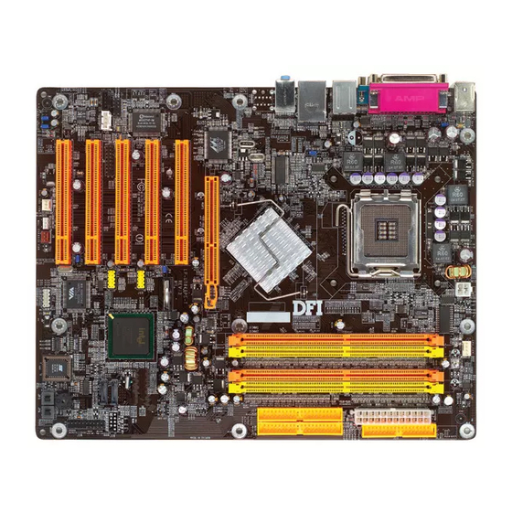
Hardware Installation Chapter 2 - Hardware Installation 2.1 System Board Layout CPU fan +12V power Mouse DDR 2 DDR 4 PS/2 power power DDR 1 DDR 3 select (JP1) S/PDIF- S/PDIF- IEEE 1394_1 USB 1-2 USB 1-4 power USB 3-4 select (JP2) Line-in Line-out... -
Page 17: System Memory
Hardware Installation Warning: Electrostatic discharge (ESD) can damage your system board, processor, disk drives, add-in boards, and other components. Perform the upgrade instruction procedures described at an ESD workstation only. If such a station is not available, you can provide some ESD protection by wearing an antistatic wrist strap and attaching it to a metal part of the system chassis. - Page 18 Hardware Installation The system board supports the following memory interface. Single Channel (SC) Data will be accessed in chunks of 64 bits (8B) from the memory channels. Virtual Single Channel (VSC) If both channels are populated with different memory configurations, the MCH defaults to Virtual Single Channel.
- Page 19 Hardware Installation The table below lists the various optimal operating modes that should be configured for the memory channel operation. Config DDR 1 DDR 2 DDR 3 DDR 4 No memory Single channel A Single channel A Single channel A Single channel B Single channel B Single channel B...
- Page 20 Hardware Installation DDR 3 DDR 4 DDR 1 DDR 2 Config P(*)(2,4) P(*)(2,4) Dynamic Mode Addressing P(*)(1,3) P(*)(1,3) Dynamic Mode Addressing P(*)(1,3) P(*)(2,4) P(*)(1,3) P(*)(2,4) Dynamic Mode Addressing P(*)(2,4) P(*)(2,4) Dynamic Mode Addressing P(*)(1,3) Dynamic Mode Addressing P(*)(1,3) P(*)(1,3) P(*)(2,4) Dynamic Mode Addressing P(*)(1,3) P(*)(2,4)
-
Page 21: Installing The Dim Module
Hardware Installation 2.2.1 Installing the DIM Module A DIM module simply snaps into a DIMM socket on the system board. Pin 1 of the DIM module must correspond with Pin 1 of the socket. Notch Pin 1 1. Pull the “tabs” which are at the ends of the socket to the side. 2. -
Page 22: Cpu
Hardware Installation 2.3 CPU 2.3.1 Overview The system board is equipped with a surface mount LGA 775 socket. This socket is exclusively designed for installing a LGA 775 packaged Prescott CPU. Important: 1. Before you proceed, make sure (1) the LGA775 1. - Page 23 Hardware Installation Important: The CPU socket must not come in contact with anything other than the CPU. Avoid unnecessary exposure. Remove the protective cap only when you are about to install the CPU. 4. The CPU socket comes with a cover that is attached with a removable protective cap.
- Page 24 Hardware Installation 7. Now lift the cover. Cover 8. Position the CPU above the socket. The gold mark on the CPU must align with pin 1 of the CPU socket. Important: Handle the CPU by its edges and avoid touching the pins. Gold mark Pin 1 of the socket...
- Page 25 Hardware Installation 9. Insert the CPU into the socket until it is seated in place. The CPU will fit in only one orientation and can easily be inserted without exerting any force. Important: Do not force the CPU into the socket. Forcing the CPU into the socket may bend the pins and damage the CPU.
-
Page 26: Installing The Fan And Heat Sink
Hardware Installation 11. Push the lever down to lock the socket. The lever should hook onto the side tab to indicate that the CPU is completely secured in the socket. 2.3.3 Installing the Fan and Heat Sink The CPU must be kept cool by using a CPU fan with heat sink. Without sufficient air circulation across the CPU and heat sink, the CPU will overheat damaging both the CPU and system board. - Page 27 Hardware Installation 2. Place the heat sink on top of the CPU. The 4 studs around the heat sink which are used to secure the heat sink onto the system board must match the 4 mounting holes around the socket. Position each stud so that the groove faces the heat sink then push it down firmly until it clicks into place.
-
Page 28: Jumper Settings
Hardware Installation 2.4 Jumper Settings 2.4.1 Clear CMOS Data 1-2 On: Normal 2-3 On: (default) Clear CMOS Data If you encounter the following, a) CMOS data becomes corrupted. b) You forgot the supervisor or user password. c) You are unable to boot-up the computer system because the processor’s ratio/clock was incorrectly set in the BIOS. - Page 29 Hardware Installation 4. After powering-on the system, press <Del> to enter the main menu of the BIOS. 5. Select the Genie BIOS Setting submenu and press <Enter>. 6. Set the processor’s ratio/clock to its default setting or an appropriate ratio or bus clock. Refer to the Genie BIOS Setting section in chapter 3 for more information.
- Page 30 Hardware Installation 2.4.2 PS/2 Power Select 1-2 On: 5V 2-3 On: 5VSB (default) JP1 is used to select the power of the PS/2 keyboard/mouse port. Selecting 5VSB will allow you to use the PS/2 keyboard or PS/2 mouse to wake up the system. BIOS Setting Configure the PS/2 keyboard/mouse wake up function in the Integrated Peripherals submenu (“Super IO Device”...
-
Page 31: Usb Power Select
Hardware Installation 2.4.3 USB Power Select USB 1-4 (JP2) 1-2 On: 5V 2-3 On: 5VSB (default) USB 5-8 (JP3) 1-2 On: 5V 2-3 On: 5VSB (default) JP2 and JP3 are used to select the power of the USB por ts. Selecting 5VSB will allow you to use the USB keyboard or USB mouse to wake up the system.. -
Page 32: Rear Panel I/O Ports
Hardware Installation 2.5 Rear Panel I/O Ports RJ45 PS/2 Parallel Mouse 1394_1 Line-in Line-out Mic-in PS/2 S/PDIF-in USB 1-2 USB 3-4 S/PDIF-out The rear panel I/O ports consist of the following: • PS/2 mouse port • PS/2 keyboard port • Parallel port •... - Page 33 Hardware Installation 2.5.1 PS/2 Mouse and PS/2 Keyboard Ports PS/2 Mouse PS/2 Keyboard The system board is equipped with an onboard PS/2 mouse (Green) and PS/2 keyboard (Purple) ports - both at location CN1 of the system board. The PS/2 mouse port uses IRQ12. If a mouse is not connected to this port, the system will reserve IRQ12 for other expansion cards.
- Page 34 Hardware Installation 2.5.2 Parallel Port Parallel The system board has a standard parallel port (Burgundy) at loca- tion CN9 for interfacing your PC to a parallel printer. It supports SPP, ECP and EPP. Setting Function Allows normal speed operation but (Standard Parallel Port) in one direction only.
- Page 35 Hardware Installation 2.5.3 S/PDIF-in/out Jacks S/PDIF-in S/PDIF-out SPDIF out SPDIF in Optical S/PDIF (J21) The system board is equipped with an onboard S/PDIF-in RCA jack (red) and a S/PDIF-out RCA jack (yellow) at locations CN2 and CN3 respectively. The S/PDIF connector at location J21 is for optical S/PDIF cable connection.
- Page 36 Hardware Installation 2.5.4 Serial Port The system board is equipped with an onboard serial port (Teal/ Turquoise) at location CN6. The serial por t is an RS-232C asynchronous communication por t with 16C550A-compatible UARTs that can be used with a modem, serial printer, remote dis- play terminal or other serial devices.
- Page 37 Hardware Installation 2.5.5 IEEE 1394 1394_1 1394_2 1 2 The system board is equipped with an onboard IEEE 1394 port at location CN7 (IEEE 1394_1) of the system board. It is also equipped with an IEEE 1394 connector at location J12 (1394_2) for connecting an additional 1394 device.
- Page 38 Hardware Installation 2.5.6 Universal Serial Bus Ports USB 2 USB 1 USB 4 USB 3 USB 5-6 USB 7-8 The system board supports 8 USB 2.0/1.1 ports. USB allows data exchange between your computer and a wide range of simultaneously accessible external Plug and Play peripherals. Four onboard USB 2.0/1.1 ports (Black) are at locations CN7 (USB 1-2) and CN8 (USB 3-4) of the system board.
- Page 39 Hardware Installation Driver Installation You may need to install the proper drivers in your operating system to use the USB device. Refer to your operating system’s manual or documentation for more information. If you are using a USB 2.0 device, install the “Intel USB 2.0 Drivers”. Refer to chapter 4 for more information.
- Page 40 Hardware Installation 2.5.7 RJ45 LAN Port The system board is equipped with an onboard RJ45 LAN port at location CN8. LAN allows the system board to connect to a local area network by means of a network hub. BIOS Setting Configure the onboard LAN in the in the Integrated Peripherals submenu (“Onboard Device”...
- Page 41 Hardware Installation 2.5.8 Audio (Rear Panel Audio and Front Audio) Line-in Line-out Mic-in Front audio Rear Panel Audio • Line-in (Light Blue) In a 2-channel or 4-channel mode, this jack is used to connect any audio devices such as Hi-fi set, CD player, tape player, AM/ FM radio tuner, synthesizer, etc.
- Page 42 Hardware Installation 4-channel 2-channel 6-channel Line-in Light Blue Line-in Center/Subwoofer Front R/L Lime Line-out Front R/L Rear R/L Pink Mic-in Rear R/L Front Audio The front audio connector (J4) allows you to connect to the line-out and mic-in jacks that are at the front panel of your system. Using this connector will disable the rear audio’s line-out and mic-in func- tions.
-
Page 43: I/O Connectors
Hardware Installation 2.6 I/O Connectors 2.6.1 CD-in Internal Audio Connector Ground Ground Right audio Left audio channel channel The CD-in (J2) connector is used to receive audio from a CD-ROM drive, TV tuner or MPEG card. - Page 44 Hardware Installation 2.6.2 Floppy Disk Drive Connector The system board is equipped with a shrouded floppy disk drive connector that supports two standard floppy disk drives. To prevent improper floppy cable installation, the shrouded floppy disk header has a keying mechanism. The 34-pin connector on the floppy cable can be placed into the header only if pin 1 of the connector is aligned with pin 1 of the header.
-
Page 45: Serial Ata Connectors
Hardware Installation 2.6.3 Serial ATA Connectors SATA 2 SATA 1 The system board is equipped with two Serial ATA connectors for connecting Serial ATA devices. Connect one end of the Serial ATA cable to J15 (SATA 1) or J14 (SATA 2) and the other end to your Serial ATA device. - Page 46 Hardware Installation 2.6.4 IDE Disk Drive Connectors IDE 2 IDE 1 The system board is equipped with two shrouded PCI IDE headers that will interface four Enhanced IDE (Integrated Drive Electronics) disk drives. To prevent improper IDE cable installation, each shrouded PCI IDE header has a keying mechanism.
- Page 47 Hardware Installation Note: Refer to your disk drive user’s manual for information about selecting proper drive switch settings. Adding a Second IDE Disk Drive When using two IDE drives, one must be set as the master and the other as the slave. Follow the instructions provided by the drive manufacturer for setting the jumpers and/or switches on the drives.
- Page 48 Hardware Installation 2.6.5 IrDA Connector IRRX N. C. Ground IRTX Connect the cable connector from your IR module to the IR connector (J1). Note: The sequence of the pin functions on some IR cable may be reversed from the pin function defined on the system board. Make sure to connect the cable connector to the IR connector according to their pin functions.
-
Page 49: Cooling Fan Connectors
Hardware Installation 2.6.6 Cooling Fan Connectors Sense Power Speed Ground Control CPU fan Ground Sense Ground N. C. Power Power 2nd fan Chassis fan Connect the CPU fan’s cable connector to the CPU fan connector (J13) on the system board. 2nd fan (J7) and chassis fan (J9) are used to connect additional cooling fans. - Page 50 Hardware Installation 2.6.7 LEDs DRAM Standby Power LED PCI Standby Power LED DIMM Standby Power LED This LED will turn red when the system’s power is on or when it is in the Suspend state (Power On Suspend or Suspend to RAM). It will not light when the system is in the Soft-Off state.
-
Page 51: Power Connectors
Hardware Installation 2.6.8 Power Connectors +12V +12V Ground Ground 1 3 1 +3.3VDC +3.3VDC -12VDC +3.3VDC +5VDC PS_ON# +5VDC PWR_OK +5VSB +5VDC +5VDC +12VDC +5VDC +12VDC +3.3VDC We recommend that you use a power supply that complies with the ATX12V Power Supply Design Guide Version 1.1. An ATX12V power supply has a standard 24-pin ATX main power connector and a 4-pin +12V power connector that must be inserted onto CN11 and CN10 connectors respectively. - Page 52 Hardware Installation 2.6.9 Front Panel Connectors PWR-LED HD-LED RESET ATX-SW SPEAKER 1 9 2 0 HD-LED: Primary/Secondary IDE LED This LED will light when the hard drive is being accessed. RESET: Reset Switch This switch allows you to reboot without having to power off the system thus prolonging the life of the power supply or system.
- Page 53 Hardware Installation PWR-LED: Power/Standby LED When the system’s power is on, this LED will light. When the system is in the S1 (POS - Power On Suspend) or S3 (STR - Suspend To RAM) state, it will blink every second. Note: If a system did not boot-up and the Power/Standby LED did not light after it was powered-on, it may indicate that the CPU...
- Page 54 Hardware Installation 2.6.10 EZ Touch Switches Power Switch Reset Switch The presence of the power switch and reset switch on the system board are user-friendly especially to DIY users. They provide convenience in powering on and/or resetting the system while fine tuning the system board before it is installed into the system chassis.
-
Page 55: Chapter 3 - Bios Setup
BIOS Setup Chapter 3 - BIOS Setup 3.1 Award BIOS Setup Utility The Basic Input/Output System (BIOS) is a program that takes care of the basic level of communication between the processor and peripherals. In addition, the BIOS also contains codes for various advanced features found in this system board. -
Page 56: Standard Cmos Features
BIOS Setup 3.1.1 Standard CMOS Features Use the arrow keys to highlight “Standard CMOS Features” and press <Enter>. A screen similar to the one below will appear. The settings on the screen are for reference only. Your version may not be identical to this one. - Page 57 BIOS Setup 3.1.1.3 IDE Channel 0 Master, IDE Channel 0 Slave, IDE Channel 1 Master and IDE Channel 1 Slave Move the cursor to the “IDE Channel 0 Master”, “IDE Channel 0 Slave”, “IDE Channel 1 Master” or “IDE Channel 1 Slave” field, then press <Enter>.
- Page 58 BIOS Setup Access Mode For hard drives larger than 528MB, you would typically select the LBA type. Certain operating systems require that you select CHS or Large. Please check your operating system’s manual or Help desk on which one to select. Capacity Displays the approximate capacity of the disk drive.
- Page 59 BIOS Setup 3.1.1.4 Drive A This field identifies the type of floppy disk drive installed. None No floppy drive is installed 360K, 5.25 in. 5-1/4 in. standard drive; 360KB capacity 1.2M, 5.25 in. 5-1/4 in. AT-type high-density drive; 1.2MB capacity 720K, 3.5 in.
- Page 60 BIOS Setup 3.1.1.7 Base Memory Displays the amount of base (or conventional) memory installed in the system. The value of the base memory is typically 512K for systems with 512K memory installed on the motherboard or 640K for systems with 640K or more memor y installed on the motherboard.
-
Page 61: Advanced Bios Features
BIOS Setup 3.1.2 Advanced BIOS Features The Advanced BIOS Features allows you to configure your system for basic operation. Some entries are defaults required by the system board, while others, if enabled, will improve the performance of your system or let you set some features according to your preference. The screen above list all the fields available in the Advanced BIOS Features submenu, for ease of reference in this manual. - Page 62 BIOS Setup 3.1.2.1 CPU Feature Move the cursor to this field and press <Enter>. The following screen will appear. The settings on the screen are for reference only. Your version may not be identical to this one. Delay Prior To Thermal This field is used to select the time that would force the CPU to a 50% duty cycle when it exceeds its maximum operating temperature therefore protecting the CPU and the system board from...
- Page 63 BIOS Setup Limit CPUID MaxVal The CPUID instruction of some newer CPUs will return a value greater than 3. The default is Disabled because this problem does not exist in the Windows series operating systems. If you are using an operating system other than Windows, this problem may occur. To avoid this problem, enable this field to limit the return value to 3 or lesser than 3.
- Page 64 BIOS Setup 3.1.2.3 Virus Warning This field protects the boot sector and partition table of your hard disk drive. When this field is enabled, the Award BIOS will monitor the boot sector and partition table of the hard disk drive. If an attempt is made to write to the boot sector or partition table of the hard disk drive, the BIOS will halt the system and an error message will appear.
- Page 65 BIOS Setup 3.1.2.8 USB Flash Disk Type Auto Automatically detects the USB device. Emulates the USB flash disk to HDD mode. Floppy Emulates the USB flash disk to floppy mode. 3.1.2.9 First Boot Device, Second Boot Device, Third Boot Device and Boot Other Device Select the drive to boot first, second and third in the “First Boot Device”...
- Page 66 BIOS Setup 3.1.2.13 Typematic Rate Setting Disabled Continually holding down a key on your keyboard will cause the BIOS to report that the key is down. Enabled The BIOS will not only report that the key is down, but will first wait for a moment, and, if the key is still down, it will begin to report that the key has been depressed repeatedly.
- Page 67 BIOS Setup 3.1.2.18 MPS Version Control for OS This field is used to select the MPS version that the system board is using. 3.1.2.19 OS Select for DRAM > 64MB This field allows you to access the memory that is over 64MB in OS/2.
- Page 68 BIOS Setup 3.1.2.23 OSB Logo Show This field is used to enable the Intel on-screen branding logo during system boot-up. It is applicable to a system that uses the Intel CPU. Enabled The logo will appear during system boot-up. Disabled The logo will not appear during system boot-up. 3.1.2.24 Small Logo(EPA) Show Enabled The EPA logo will appear during system boot-up.
-
Page 69: Advanced Chipset Features
BIOS Setup 3.1.3 Advanced Chipset Features The settings on the screen are for reference only. Your version may not be identical to this one. This section gives you functions to configure the system based on the specific features of the chipset. The chipset manages bus speeds and access to system memory resources. - Page 70 BIOS Setup If you selected “Fast” or “Turbo”: • Make sure to use DDR400. • It may cause instability to the system. If this happens, set this field to “User Define”. • The “CAS Latency Time”, “Active to Precharge Delay”, “DRAM RAS# to CAS# Delay”...
- Page 71 BIOS Setup 3.1.3.6 DRAM RAS# to CAS# Delay The options are 2, 3 and 4. 3.1.3.7 DRAM RAS# Precharge This field controls RAS# precharge (in local memory clocks). 3.1.3.8 Memory Frequency For This field is used to select the memory clock speed of the DIMM. The system board suppor ts DDR333 or DDR400 when using 800MHz FSB CPU.
- Page 72 BIOS Setup 3.1.3.11 Memory Hole At 15M-16M In order to improve system performance, certain space in memory can be reserved for ISA cards. This memory must be mapped into the memory space below 16MB. When enabled, the CPU assumes the 15- 16MB memory range is allocated to the hidden ISA address range instead of the actual system DRAM.
- Page 73 BIOS Setup 3.1.3.18 Selective CPC The options are Auto, Enabled and Disabled. 3.1.3.19 Turbo Mode Set this field to Enabled to allow DDR400 to run in Turbo mode.
-
Page 74: Integrated Peripherals
BIOS Setup 3.1.4 Integrated Peripherals The settings on the screen are for reference only. Your version may not be identical to this one. 3.1.4.1 OnChip IDE Device Move the cursor to this field and press <Enter>. The following screen will appear. The settings on the screen are for reference only. - Page 75 BIOS Setup IDE HDD Block Mode Enabled The IDE HDD uses the block mode. The system BIOS will check the hard disk drive for the maxi- mum block size the system can transfer. The block size will depend on the type of hard disk drive. Disabled The IDE HDD uses the standard mode.
- Page 76 BIOS Setup IDE Primary Master/Slave UDMA and IDE Secondary Master/ Slave UDMA These fields allow you to set the Ultra DMA in use. When Auto is selected, the BIOS will select the best available option after checking your hard drive or CD-ROM. Auto The BIOS will automatically detect the settings for you.
- Page 77 BIOS Setup 3.1.4.2 Onboard Device Move the cursor to this field and press <Enter>. The following screen will appear. The settings on the screen are for reference only. Your version may not be identical to this one. USB Controller This field is used to enable or disable the onboard USB. USB 2.0 Controller If you are using a USB 2.0 device, this field must be set to Enabled.
- Page 78 BIOS Setup Onboard 1394 Device This field is used to enable or disable the onboard 1394. BIOS Flash Protect Enabled This option will protect the system from unnecessary updating or flashing of the BIOS. When enabled, it secures the BIOS therefore any updates to the BIOS will not take effect.
- Page 79 BIOS Setup 3.1.4.3 Super IO Device Move the cursor to this field and press <Enter>. The following screen will appear. The settings on the screen are for reference only. Your version may not be identical to this one. KBC Input Clock This is used to select the input clock of your keyboard.
- Page 80 BIOS Setup Any Key Press any key to power-on the system. Keyboard 98 When this option is selected, press the “wake up” key of the Windows 98 compatible keyboard to power-on the system. KB Power On Password Move the cursor to this field and press <Enter>. Enter your pass- word.
- Page 81 BIOS Setup UART Port Select This field is used to select an I/O address for the IrDA device. UART Mode Select This field is used to select the type of IrDA standard supported by your IrDA device. For better transmission of data, your IrDA peripheral device must be within a 30 angle and within a distance of 1 meter.
- Page 82 BIOS Setup Parallel Port Mode The options are SPP, EPP, ECP and ECP+EPP. These apply to a standard specification and will depend on the type and speed of your device. Refer to your peripheral’s manual for the best option. Allows normal speed operation but in one direction only. “ECP (Extended Capabilities Port)”...
- Page 83 BIOS Setup Game Port Address This field is used to select the game port’s address. Midi Port Address This field is used to select the midi port’s address. If you have selected the midi port’s address, you may select its IRQ in the “Midi Port IRQ”...
-
Page 84: Power Management Setup
BIOS Setup 3.1.5 Power Management Setup The Power Management Setup allows you to configure your system to most effectively save energy. The settings on the screen are for reference only. Your version may not be identical to this one. 3.1.5.1 ACPI Function This function should be enabled only in operating systems that sup- ®... - Page 85 BIOS Setup 3.1.5.3 Run VGABIOS if S3 Resume When this field is set to Auto, the system will initialize the VGA BIOS when it wakes up from the S3 state. This can be configured only if the “ACPI Suspend Type” field is set to “S3(STR)”. 3.1.5.4 Power Management This field allows you to select the type (or degree) of power saving by changing the length of idle time that elapses before the Suspend...
- Page 86 BIOS Setup 3.1.5.8 MODEM Use IRQ This field is used to set an IRQ channel for the modem installed in your system. 3.1.5.9 Suspend Mode This is selectable only when the Power Management field is set to User Define. When the system enters the Suspend mode according to the power saving time selected, the CPU and onboard peripherals will be shut off.
- Page 87 BIOS Setup 3.1.5.12 Wake-Up by PCI Card Enabled This field should be set to Enabled only if your PCI card such as LAN card or modem card uses the PCI PME (Power Management Event) signal to remotely wake up the system. Access to the LAN card or PCI card will cause the system to wake up.
- Page 88 BIOS Setup 3.1.5.17 Date (of Month) Alarm The system will power-on everyday according to the time set in the “Time (hh:mm:ss) Alarm” field. 1-31 Select a date you would like the system to power-on. The system will power-on on the set date, and time set in the “Time (hh:mm:ss) Alarm”...
-
Page 89: Pnp/Pci Configurations
BIOS Setup 3.1.6 PnP/PCI Configurations This section describes configuring the PCI bus system. It covers some very technical items and it is strongly recommended that only experienced users should make any changes to the default settings. The settings on the screen are for reference only. Your version may not be identical to this one. - Page 90 BIOS Setup 3.1.6.3 IRQ Resources Move the cursor to this field and press <Enter>. This field is used to set each system interrupt to either Reserved or PCI Device. The settings on the screen are for reference only. Your version may not be identical to this one.
-
Page 91: Pc Health Status
BIOS Setup 3.1.7 PC Health Status The settings on the screen are for reference only. Your version may not be identical to this one. 3.1.7.1 Shutdown Temperature You can prevent the system from overheating by selecting a tem- perature in this field. If the system detected that its temperature exceeded the one set in this field, it will automatically shutdown. -
Page 92: Genie Bios Setting
BIOS Setup 3.1.8 Genie BIOS Setting The settings on the screen are for reference only. Your version may not be identical to this one. 3.1.8.1 Super Patch Enabled Enables the Super Patch feature but will work ONLY when using 800MHz FSB and DDR400. Make sure to use this CPU/DIMM combination to boost system per- formance. - Page 93 BIOS Setup 3.1.8.5 CPU Clock This field provides several options for selecting the external system bus clock of the processor. The available options allow you to adjust the processor’s bus clock by 1MHz increment. Important: Selecting an external bus clock other than the default setting may result to the processor’s or system’s instability and are not guaranteed to provide better system performance.
- Page 94 BIOS Setup 3.1.8.11 Chips Voltage Control This field allows you to manually select higher voltage supplied to the chipset. If you want to use the default voltage, leave this field in its default setting. Important: Although this function is supported, we do not recommend that you use a higher voltage because unstable current may be supplied to the system board causing damage.
-
Page 95: Cmos Reloaded
BIOS Setup 3.1.9 CMOS Reloaded The screen above list all the fields available in the CMOS Reloaded submenu, for ease of reference in this manual. In the actual CMOS setup, you have to use the scroll bar to view the fields. The settings on the screen are for reference only. Your version may not be identical to this one. - Page 96 BIOS Setup Auto Save Bootable Setting This field is used to automatically save the last bootable setting from CMOS to an area in the SEEPROM referred to as the backup bank. To use this function: 1. Set this field to Enabled. 2.
- Page 97 BIOS Setup Saving, Loading and Naming BIOS Settings For overclockers who require different sets of settings for various system environments or operating systems, CMOS Reloaded allows you to save, load and name up to four sets of BIOS settings - in the “User Defined Setting Bank #1”...
- Page 98 BIOS Setup Load from this Bank To load the setting saved in the bank, move the cursor to “Load from this Bank” then press <Enter>. The setting in this bank will replace the current setting. Make sure to save before you exit the BIOS setup utility by selecting “Y”...
-
Page 99: Load Optimized Defaults
BIOS Setup 3.1.10 Load Optimized Defaults The “Load Optimized Defaults” option loads optimized settings from the BIOS ROM. Use the default values as standard values for your system. Highlight this option in the main menu and press <Enter>. Type <Y> and press <Enter> to load the Setup default values. -
Page 100: Set Supervisor Password
BIOS Setup 3.1.11 Set Supervisor Password If you want to protect your system and setup from unauthorized entry, set a supervisor’s password with the “System” option selected in the Advanced BIOS Features. If you want to protect access to setup only, but not your system, set a supervisor’s password with the “Setup”... -
Page 101: Set User Password
BIOS Setup 3.1.12 Set User Password If you want another user to have access only to your system but not to setup, set a user’s password with the “System” option se- lected in the Advanced BIOS Features. If you want a user to enter a password when trying to access setup, set a user’s password with the “Setup”... - Page 102 BIOS Setup 3.1.13 Save & Exit Setup When all the changes have been made, highlight “Save & Exit Setup” and press <Enter>. Type “Y” and press <Enter>. The modifications you have made will be written into the CMOS memory, and the system will reboot. You will once again see the initial diagnostics on the screen.
-
Page 103: Exit Without Saving
BIOS Setup 3.1.14 Exit Without Saving When you do not want to save the changes you have made, highlight “Exit Without Saving” and press <Enter>. Type “Y” and press <Enter>. The system will reboot and you will once again see the initial diagnostics on the screen. If you wish to make any changes to the setup, press <Ctrl>... -
Page 104: Updating The Bios
BIOS Setup 3.2 Updating the BIOS To update the BIOS, you will need the new BIOS file and a flash utility, AWDFLASH.EXE. You can download them from DFI’s web site or contact technical support or your sales representative. Note: AWDFLASH.EXE works only in DOS mode. 1. - Page 105 BIOS Setup 6. The following will appear. Do You Want to Save BIOS (Y/N) This question refers to the current existing BIOS in your system. We recommend that you save the current BIOS and its flash utility; just in case you need to reinstall the BIOS. To save the current BIOS, press <Y>...
-
Page 106: Chapter 4 - Supported Software
Supported Software Chapter 4 - Supported Software 4.1 Drivers, Utilities and Software Applications The CD that came with the system board contains drivers, utilities and software applications required to enhance the performance of the system board. Inser t the CD into a CD-ROM drive. The autorun screen (Mainboard Utility CD) will appear. - Page 107 Supported Software 4.1.1 Intel Chipset Software Installation Utility The Intel Chipset Software Installation Utility is used for updating Windows 98/98SE/2000/ME/XP's INF files so that the Intel chipset can be recognized and configured properly in the system. To install the utility, please follow the steps below. 1.
- Page 108 Supported Software 4.1.2 Audio Drivers To install, please follow the steps below. 1. On the left side of the autorun screen, click the “AUDIO” icon. 2. Click “Audio Drivers” on the main menu. The following screen will appear. 3. Follow the prompts on the screen to complete installation. 4.
-
Page 109: Intel Usb 2.0 Drivers
Supported Software 4.1.3 Intel USB 2.0 Drivers If you are using a USB 2.0 device, you must install the USB 2.0 driver. The drivers are supported in the following operating systems: Windows 98 SE, Windows ME and Windows 2000. - Page 110 Supported Software Windows 2000 does not support auto-installation of the USB 2.0 driver. When you click “Intel USB 2.0 Drivers”, the “readme” screen will appear. 3. Follow the installation instructions shown on the screen. 4. Reboot the system for the driver to take effect. Important: ®...
-
Page 111: Lan Drivers
Supported Software 4.1.4 LAN Drivers To install, please follow the steps below. 1. On the left side of the autorun screen, click the “NETWORK” icon. 2. Click “LAN Drivers” on the main menu. The following screen will appear. 3. Follow the prompts on the screen to complete installation. 4. - Page 112 Supported Software 4.1.5 Hardware Monitor The system board comes with the Hardware Monitor utility con- tained in the provided CD. This utility is capable of monitoring the system’s “health” conditions and allows you to manually set a range (Highest and Lowest Limit) to the items being monitored. If the settings/values are over or under the set range, a warning message will pop-up.
-
Page 113: Microsoft Directx
Supported Software 4.1.6 Microsoft DirectX 9 To install, please follow the steps below. 1. On the left side of the autorun screen, click the “TOOLS” icon. 2. Click “Microsoft DirectX 9” on the main menu. The following screen will appear. 3. -
Page 114: Installation Notes
Supported Software 4.2 Installation Notes 1. "Autorun" ONLY supports the Windows 98, Windows 98 SE, Windows ME, Windows 2000, Windows NT 4.0 and Windows XP operating systems. If after inser ting the CD, "Autorun" did not automatically start (which is, the Main Board Utility CD screen did not appear), please go directly to the root directory of the CD and double-click "Setup". -
Page 115: Enabling The Hyper-Threading Technology
Enabling Hyper-Threading Technology Appendix A - Enabling Hyper-Threading Technology A.1 Enabling Hyper-Threading Technology To enable the functionality of the Hyper-Threading Technology, please follow the requirements and steps below. Basically, the following ® ® presumes that you have already installed an Intel Pentium Processor with Hyper-Threading Technology. - Page 116 Enabling Hyper-Threading Technology Click the General tab. The processor shown under Computer should resemble the one shown below. Now click the Hardware tab then click Device Manager. The items shown under Computer and Processors should resemble the ones shown below.
- Page 117 Enabling Hyper-Threading Technology Lastly, press the <Ctr l> <Alt> and <Del> keys simultaneously. The Windows Task Manager dialog box will appear. Click the Performance tab. The diagram under CPU Usage History should resemble the one shown below.
-
Page 118: Appendix B - System Error Messages
System Error Message Appendix B - System Error Message When the BIOS encounters an error that requires the user to correct something, either a beep code will sound or a message will be displayed in a box in the middle of the screen and the message, PRESS F1 TO CONTINUE, CTRL-ALT-ESC or DEL TO ENTER SETUP, will be shown in the information box at the bottom. - Page 119 System Error Message setting than indicated in Setup. Determine which setting is correct, either turn off the system and change the jumper or enter Setup and change the VIDEO selection. FLOPPY DISK(S) fail (80) Unable to reset floppy subsystem. FLOPPY DISK(S) fail (40) Floppy type mismatch.
-
Page 120: Appendix C - Troubleshooting
Troubleshooting Appendix C - Troubleshooting C.1 Troubleshooting Checklist This chapter of the manual is designed to help you with problems that you may encounter with your personal computer. To efficiently troubleshoot your system, treat each problem individually. This is to ensure an accurate diagnosis of the problem in case a problem has multiple causes. -
Page 121: Power Supply
Troubleshooting The picture seems to be constantly moving. 1. The monitor has lost its vertical sync. Adjust the monitor’s vertical sync. 2. Move away any objects, such as another monitor or fan, that may be creating a magnetic field around the display. 3. -
Page 122: Parallel Port
Troubleshooting Hard Drive Hard disk failure. 1. Make sure the correct drive type for the hard disk drive has been entered in the BIOS. 2. If the system is configured with two hard drives, make sure the bootable (first) hard drive is configured as Master and the second hard drive is configured as Slave. -
Page 123: Serial Port
Troubleshooting Serial Port The serial device (modem, printer) doesn’t output anything or is outputting garbled characters. 1. Make sure that the serial device’s power is turned on and that the device is on-line. 2. Verify that the device is plugged into the correct serial port on the rear of the computer.
Need help?
Do you have a question about the UT 865PE-T and is the answer not in the manual?
Questions and answers