Table of Contents
Advertisement
Advertisement
Table of Contents

Related Manuals for Daikin Enfinity VFC


Summary of Contents for Daikin Enfinity VFC
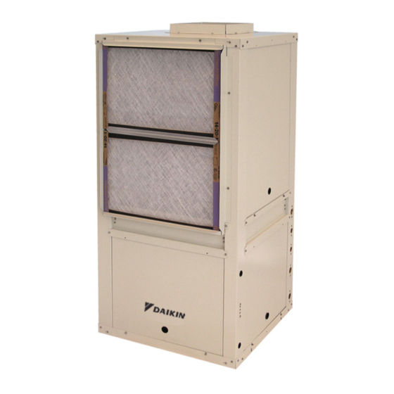
- Page 1 Installation and Maintenance Manual IM 930-6 Group: WSHP Part Number: 910157591 Date: September 2014 Enfinity™ Vertical Water Source Heat Pumps Model VFC Standard Range & VFW Geothermal Unit Sizes 009 – 070 / R-410A Refrigerant People and ideas you can trust. ™...
-
Page 3: Table Of Contents
ontents Model Nomenclature . . . . . . . . . . . . . . . . . . . . . . . . . . 4 Thermostat Connections . -
Page 4: Model Nomenclature
odel oMenClature Category Code Item Code Option Code Designation & Description Product Category = Water Source Heat Pump Product Identifier VFC = R410A, Floor Mounted, Standard Range VFW = R410A, Floor Mounted, Geothermal Range Design Series (Vintage) = A Design = B Design = C Design = D Design Nominal Capacity 009 = 9,000 Btuh Nominal Cooling 012 = 12,000 Btuh Nominal Cooling 015 = 15,000 Btuh Nominal Cooling 019 = 19,000 Btuh Nominal Cooling... -
Page 5: Receiving And Storage
eCeiving and torage Pre-Installation CAUTION WARNING Sharp edges can cause personal injury. Avoid contact with them. Use care and wear protective clothing, safety glasses and gloves The installer must determine and follow all applicable codes when handling parts and servicing heat pumps. and regulations. This equipment presents hazards of electricity, rotating parts, sharp edges, heat and weight. Failure to read and Upon receipt of the equipment, check carton for visible follow these instructions can result in property damage, severe damage. Make a notation on the shipper’s delivery personal injury or death. This equipment must be installed by ticket before signing. If there is any evidence of rough experienced, trained personnel only. handling, immediately open the cartons to check for concealed damage. If any damage is found, notify To prevent damage, do not operate this equipment the carrier within 48 hours to establish your claim and for supplementary heating and cooling during the request their inspection and a report. The Warranty construction period. -
Page 6: Locating The Unit
oCating Locate the unit in an area that allows for easy A Condensate removal of the filter and access panels, and has B Desuperheater Water Return (Optional) enough space for service personnel to perform C Desuperheater Water Supply (Optional) maintenance or repair. Provide sufficient room to D Water Return make water, electrical and duct connections. E Water Supply Make sure that sufficient access has been provided for installing the unit, including clearance for duct collars Figure 2: Typical closet installation with ducted return and fittings at water and electrical connections. Allow adequate room around the unit for a condensate piping. Return Return The unit can be installed “free standing” in an Duct & Duct & Grille Grille equipment room. However, closet installations are more common for small vertical type units. Generally, the unit is located in the corner of a closet with the non-ducted return air facing 90° to the door and the major access panels facing the door as in Figure 1. -
Page 7: Unit Installation
nstallation Ductwork and Attenuation The transition piece must not have an angle greater than 30° or severe loss of air performance can result. Do Discharge ductwork is normally used with these units. not connect the full duct size to the unit without using a Where return air ductwork is required, the unit is transition piece down to the size of the discharge collar supplied with a 1" filter rack/duct collar for connection of on the unit. With metal duct material, the sides of the return air ductwork. An optional 2" return air duct collar elbow and entire branch duct should be internally lined filter rack is available as a field-installed accessory or with acoustic insulation for sound attenuation. Glass a factory-installed, selectable option. The 2" filter rack fiber duct board material is more absorbing and may allows tool less entry for easy filter replacement. permit omission of the flexible connector. Figure 4: Sizes 007 thru 070 Optional 2" Return Air Duct The ductwork should be laid out so that there is no line Collar Filter Rack of sight between the unit discharge and the distribution diffusers. Return Air Ducting Return air ducts can be brought in through a wall grille and then to the unit. The return duct system will normally consist of a flexible connector at the unit and a trunk... -
Page 8: Ventilation Air
nstallation Ventilation Air While circulating water, the contractor should check and repair any leaks in the unit and surrounding piping. Outside air may be required for ventilation. The Drains at the lowest point(s) in the system should be temperature of the ventilation air must be controlled so opened for initial flush and blow-down, making sure city that mixture of outside air and return air entering the water fill valves are set to make up water at the same unit does not exceed application limits. It is also general rate. Check the pressure gauge at pump suction and practice to close off the ventilation air system during manually adjust the makeup to hold the same positive unoccupied periods (night setback). steady pressure both before and after opening the drain The ventilation air system is generally a separate valves. Flush should continue for at least two hours or building subsystem with distribution ductwork. To provide longer until the drain water is clean and clear. thorough mixing of the outside and return air, introduce the outside air in close proximity to the return air plenum CAUTION inlet. Do not duct outside air directly to the unit inlet. See Units must be checked for water leaks upon initial water system "Operating Limits" on page 9 . start-up. Water leaks may be a result of mishandling or damage during shipping. Failure by the installing contractor to check for CAUTION leaks upon start-up of the water system could result in property damage. Prior to making piping connections, contractor must clean and flush water loop system. Failure to clean/flush system may result Shut off supplemental heater and circulator pump in nuisance tripping and premature component failure. -
Page 9: Operating Limits
nstallation Operating Limits This equipment is designed for indoor installation only. Sheltered locations such as attics, garages, etc., generally will not provide sufficient protection against extremes in temperature and/or humidity, and equipment performance, reliability, and service life may be adversely affected. Table 2: Air limits in °F (°C) Standard Range Units Geothermal Range Units Air Limits Cooling Heating Cooling Heating Minimum Ambient Air 50°F (10°C) 50°F (10°C) 40°F (4°C) 40°F (4°C) Rated Ambient 80°F (27°C) 70°F (21°C) 80°F (27°C) 70°F (21°C) Maximum Ambient Air 100°F (38°C) 85°F (29°C) 100°F (38°C) -
Page 10: Piping
nstallation Piping Condensate piping can be steel, copper or PVC. Each unit includes a condensate connection. All units should be connected to supply and return piping in a two-pipe reverse return configuration. A Units are internally trapped. reverse return system is inherently self-balancing Do not locate any point in the drain system above and requires only trim balancing where multiple the drain connection of any unit. quantities of units with different flow and pressure drop characteristics exist in the same loop. Check for proper 10 . Automatic flow controlled devices must not be water balance by measuring differential temperature installed prior to system cleaning and flushing. reading across the water connections. For proper 11 . A high point of the piping system must be vented. water flow, the differential temperature should be 12°F to 14°F (5°C to 8°C) for units in cooling mode. 12 . Check local code for the need for dielectric fittings. A direct return system may also work, but proper water flow balancing is more difficult to achieve and maintain. Note: Do not over-torque fittings. The maximum torque without damage to fittings is 30 foot pounds. If a The piping can be steel, copper or PVC. -
Page 11: Electrical Connections
nstallation Electrical Connections Note: Voltages listed are to show voltage range. How- ever, units operating with over voltage and under Note: Installation and maintenance must be performed voltage for extended periods of time will experi- only by qualified personnel who are familiar with ence premature component failure. -
Page 12: Microtech ® Iii Unit Controller
ontrols MicroTech III Unit Controller Remote Reset of Automatic Lockouts ® The Remote Reset feature provides the means to The MicroTech III Unit Controller includes built-in remotely reset some lockouts generated by high-pressure features such as random start, compressor time delay, and/or low-temperature faults. When the MicroTech III unit shutdown, condensate overflow protection, defrost cycle, controller is locked out due to one of these faults, and the brownout, and LED/fault outputs. Refer to Table 10 on cause of the fault condition has been cleared, energizing page 14 . the O-terminal for 11 seconds or more forces the The unit has been designed for operation with a MicroTech III unit controller to clear the lockout. Cycling microelectronic wall thermostat selected by the unit power also clears a lockout if the conditions causing manufacturer. Do not operate the unit with any other the fault have been alleviated. type of wall thermostat. The Intelligent Alarm Reset feature helps to minimize Each unit has a printed circuit board control system. The nuisance trips of automatic reset lockouts caused by low low voltage output from the low voltage terminal strip temperature faults. This feature clears faults the first two is AC voltage to the wall thermostat. R is A/C voltage times they occur within a 24-hour period and triggers output to the wall stat. an automatic lockout on the 3rd fault. The retry count is The 24 volt low voltage terminal strip is set up so R-G reset to zero every 24 hours. - Page 13 ontrols Table 8: MicroTech® III Unit Controller Terminals H7 – 2 No Connection Locations and Descriptions H7 – 3 Red LED Output H1 – 1 24 VAC Power Input H7 – 4 Green LED Output H1 – 2 24 VAC common H7 – 5 Yellow LED Output H2 – 1 Fan Low Speed Output – Switched L1 H7 – 6 Red-Green-Yellow LED Common H2 – 2 Blank Terminal H8 – 1 Isolation Valve/Pump Request Relay N/O H2 – 3 Fan Low Speed Output – Neutral H8 – 2 Isolation Valve/Pump Request Relay N/C H3 – 1 HP1-1 Comp High Pressure Switch (HP1) Input Terminal 1 H8 – 3 24 VAC Common H3 – 2 HP1-2...
- Page 14 ontrols Table 10: MicroTech III Controller Status LED's Description Type* Yellow Green Emergency Shutdown Mode Flash Low Voltage Brownout Fault Flash High Pressure (HP1) Fault Flash Low Pressure (LP1) Fault Low Suction Temp (LT1) Sensor Fail Fault Flash Flash Low Suction Temp (LT1) Fault Flash Room Temp Sensor Fail (with Room Sensor Control Only) Fault Flash Flash Condensate Overflow (Cooling & Dehumidification Modes Only) Fault Low Entering Water Temp (Heating Compressor Inhibit; No Display with Boilerless EH) Fault Flash Flash Serial EEPROM Corrupted Fault Service Test Mode Enabled...
- Page 15 ontrols Note: A random start delay time between 300 and 360 Figure 12: Location of Configuration Jumpers on the seconds is generated at power up. MicroTech III Unit Controller Figure 11: MicroTech III Unit Controller Terminal Locations www .DaikinApplied .com Enfinity Vertical Water Source Heat Pumps •...
-
Page 16: I/O Expansion Module
I/O Expansion Module Figure 13: I/O Expansion Module Configuration Jumper Terminals Jumper Terminals This manual covers the installation of a Daikin Vertical Floor Unit - Model VFC, VFW Water Source Heat Pump. For installation and operation information on MicroTech III unit controller and other ancillary components, see: ■ IM 927 - MicroTech III Unit Controller for Water Source Heat Pumps (L orks The I/O Expansion Module is a field-installed option. It is an extension of the MicroTech III unit controller and provides extra functionality. The I/O Expansion Module has 4 main purposes: ■ The MicroTech III unit controller in combination Features with the I/O Expansion Module will be the standard control system for two-stage Water Source Heat Standard Heat Pumps / Single Circuit Pump equipment. (i.e. large vertical units). Units ■ The I/O Expansion Module has outputs to control ■... - Page 17 ontrols Table 11: I/O Expansion Module Jumper Settings I/O Expansion Description Jumper(s) Jumper Setting Model Open Single Compressor Model (factory default setting) Compressor Options Dual Compressor Model Shorted Open None (default) Hot Gas/Water Reheat (HGR) Dehumidification Shorted Hot Gas / Water Reheat (HGR) Open None Open Shorted Secondary Heating Options* JP3 & JP4 Supplemental Electric Heat Open Open Boilerless Electric Heat Shorted Open Single Speed Fan (PSC motor) Open Shorted Fan Speed Selection JP5 & JP6...
-
Page 18: Microtech Iii Controller With L On W Orks
MicroTech III Controller With Each unit controller orchestrates the following unit operations: Communication ® orks ■ Enable heating and cooling to maintain setpoint Module based on a room sensor. ■ Enable fan and compressor operation. This manual covers the installation of a Daikin Vertical Floor Unit - Model VFC, VFW Water Source Heat Pump. ■ Monitor all equipment protection controls. For installation and operation information on L orks Communication Module and other ancillary control ■ Monitor discharge air temperature. components, see: ■ Monitor leaving water temperature. ■ IM 927 - MicroTech III Water Source Heat Pump ■ Relay status of all vital unit functions. LonWorks Communication Module ■ Support optional control outputs. ■ IM 933 - LonMaker Integration Plug-in Tool: For use with the MicroTech III Unit Controller MicroTech III heat pumps with a MicroTech III unit ■... -
Page 19: Microtech Iii Controller With Bacnet Communication
Enable fan and compressor operation ■ OM 931 - MicroTech III Unit Controller for Water Source Heat Pumps Operation and Maintenance ■ Monitors all equipment protection controls Manual ■ Monitors room and discharge air temperatures ■ IM 955 - MicroTech III Wall Sensor For use with ■ Monitors leaving water temperature Microtech III Unit Controller ■ Relays status of all vital unit functions Daikin water source heat pumps are available with a BACnet MS/TP communication module that is designed The MicroTech III unit controller with to communicate over a BACnet MS/TP communications communication module includes: network to a building automation system (BAS). It can be factory or field-installed. ■ Return Air Temperature sensor (RAT)(field-installed) The unit controller is programmed and tested with all the ■ Discharge Air Temperature sensor (DAT)(field- logic required to monitor and control the unit. An optional installed) wall sensor may be used with the communication module to provide limited local control of the water ■... - Page 20 ontrols Figure 16: L Communication Module Placement on MicroTech III Unit Controller orks IM 930-6 • Enfinity Vertical Water Source Heat Pumps www .DaikinApplied .com...
-
Page 21: Prior To Start-Up
rior tart Changing PSC Fan Motor Speed Unit Size 019 through 036 (208/230/60/1) and (265/60/1) The fan motor can be changed from high to low speed or vice versa by interchanging the wires on the black and Fan motors on unit sizes 019-036, in both 208/230/60/1 red labeled terminals on the motor terminal block. and 265/60/1 voltages (Figure 18) have a four-position terminal block. To change between high and low speed, WARNING interchange the red and black wires. Hazardous Voltage! Figure 18: Sizes 019 through 036 (208/230/60/1), (265/60/1) The installer must determine and follow all applicable codes and regulations. This equipment presents hazards of electricity, rotating parts, sharp edges, heat and weight. Failure to read and follow these instructions can result in property damage, severe personal injury or death. CAUTION Sharp edges can cause personal injury. Avoid contact with them. - Page 22 rior tart Unit Size 024 through 036 (208/230/3) Figure 21: Sizes 042-070 (575/60/1) Fan motors on unit sizes 024-036 in voltages 208/230/3 (Figure 23) all have a four-position terminal block. In order to change between high and low speed, interchange the wires on the black and red terminals. Figure 23: Sizes 024-036 (208/230/3) Unit Size 042 through 070 (265/60/1), (208/230/1) & (208/230/3) Fan motors on unit sizes 042-070 in voltages 265/60/1, 208/230/1 and 208/230/3 (Figure 22) all have a five- position terminal block. In order to change between high Notes: All motors have a wiring label that is keyed for and low speed, interchange the wires on the black and proper wiring operation.
-
Page 23: Start-Up
tart After a few minutes of operation, check the discharge grilles for cool air delivery. Measure CAUTION the temperature difference between entering and Units must be checked for water leaks upon initial water system leaving water. It should be approximately 1-1⁄2 start-up. Water leaks may be a result of mishandling or damage times greater than the heating mode temperature during shipping. Failure by the installing contractor to check for difference. For example, if the cooling temperature leaks upon start-up of the water system could result in property difference is 15°F (8°C), the heating temperature damage. difference should be 10°F (5°C). Without automatic flow control valves, target a Open all valves to full open position and turn on cooling temperature difference of 10°F to 14°F (5°C power to the unit. to 8°C). Adjust the combination shutoff/balancing Set the thermostat for "Fan Only" operation by valve in the return line to a water flow rate which will selecting "Off" at the system switch and "On" at the result in the 10˚F to 14°F (5°C to 8°C) difference. fan switch. If "Auto" fan operation is selected, the Set thermostat to “Heat.” If the thermostat is the fan will cycle with the compressor. automatic changeover type, set system switch to For those units that have two-speed motors, the “Auto” position and depress the heat setting to reconnect for low speed operation if necessary the highest temperature. Some units have built-in time delays which prevent the compressor from Set thermostat to “Cool.” If the thermostat is an immediately starting. With most control schemes, automatic changeover type, simply set the cooling the fan will start immediately. After a few minutes of temperature to the lowest temperature. On manual compressor operation, check for warm air delivery changeover types, additionally select “Cool” at the at discharge grille. If this is a “cold building” start- system switch. -
Page 24: Typical Wiring Diagrams
yPiCal iring iagraMs MicroTech III Unit Controller (Standalone) – 208/230/460/575/60Hz/3-Phase Drawing No. 668991201 Shown with optional desuperheater pump wiring. Wiring diagrams are typical. For the latest drawing version refer to the wiring diagram located on the inside of the controls access panel of the unit. Note: Gray tinted areas in the wiring diagram: Units with factory installed communication module include Discharge Air Temperature (DAT) and Return Air Temperature (RAT) sensors shipped loose and are field installed. -
Page 25: 208/230/265/277/60 Hz/1-Phase
yPiCal iring iagraMs MicroTech III Unit Controller with Optional ECM Motor, Desuperheater and I/O Expansion Module - 208/230/265/277/60 Hz/1-Phase Drawing No. 668991501 Wiring diagrams are typical. For the latest drawing version refer to the wiring diagram located on the inside of the controls access panel of the unit. Note: Gray tinted areas in the wiring diagram: Units with factory installed communication module include Discharge Air Temperature (DAT) and Return Air Temperature (RAT) sensors shipped loose and are field installed. -
Page 26: Module - 208/230/460/60 Hz/3-Phase
yPiCal iring iagraMs MicroTech III Unit Controller with Optional ECM Motor, Desuperheater, Electric Heat Coil & I/O Expansion Module – 208/230/460/60 Hz/3-Phase Drawing No. 668991301 Wiring diagrams are typical. For the latest drawing version refer to the wiring diagram located on the inside of the controls access panel of the unit. -
Page 27: 208/230/460/60/3-Phase
yPiCal iring iagraMs MicroTech III Unit Controller with Optional ECM Motor, Desuperheater, and I/O Expansion Module 208/230/460/60/3-Phase Drawing No. 668991401 Wiring diagrams are typical. For the latest drawing version refer to the wiring diagram located on the inside of the controls access panel of the unit. Note: Gray tinted areas in the wiring diagram: Units with factory installed communication module include Discharge Air Temperature (DAT) and Return Air Temperature (RAT) sensors shipped loose and are field installed. -
Page 28: 208/230/60/1-Phase
yPiCal iring iagraMs MicroTech III Unit Controller with PSC Motor, Desuperheater and I/O Expansion Module for Hot Gas Reheat Control (Unit Sizes 019-070) 208/230/60/1-Phase Drawing No. 669007101A *Wiring diagrams are typical. For the latest drawing version refer to the wiring diagram located on the inside of the controls access panel of the unit. -
Page 29: Thermostat Connections
herMostat onneCtions 7-Day Programmable Electronic Optional Remote Sensor (P/N Thermostat (P/N 668375301) 66720401) Remove cover from remote sensor housing. MicroTech III Unit Control Board Low Voltage Terminal Strip (Circuit 1) Select an appropriate location for mounting the remote sensor. 24VAC Common Mount remote sensor unit using hardware provided. Tenant Override Install two strand shielded wire between remote sensor and thermostat. Shielded wire must be used. Cool 1 Cool 2 Note: Do not run remote sensor wire in conduit with Heat 1 other wires. -
Page 30: Microtech Iii Wall-Mounted Room Temperature Sensors
herMostat onneCtions MicroTech III Wall-Mounted Room Wiring Sensors to the MicroTech III Temperature Sensors (Kit P/N Unit Controller 669529101, 669529201, 669529001) Figure 27: Temperature Sensor Wiring to MicroTech III Unit Controller (669529101, 669529201) Figure 25: MicroTech III Wall-Mounted Room Temperature Sensors (669529201 Not Shown) Temperature Sensor Terminals... -
Page 31: Additional Accessories - General
– g dditional CCessories eneral Motorized Isolation Valve & Relay This version of the control uses VAC relays and should not be used in combination with any other accessories or The motorized valve kit is available as a factory-installed equipment that require VDC connections. and wired option or may be ordered as a field-installed Figure 30: Multiple Unit Control Panel and Board accessory. Wired as shown in Figure 29, the motorized valve will open on a call for compressor operation. Valves for unit sizes 009 to 019 are 1/2" while unit sizes 024 to 070 are 3/4". Using a Normally Closed (N/C), power open valve, wire as illustrated in Figure 29. Figure 29: Normally Closed, Power Open Motorized Valve & Relay Wiring Actuator &... -
Page 32: Hot Gas/Water Reheat Dehumidification (Option)
A field supplied humidistat is required. Wire the exposure to temperatures that will cause the water to freeze, humidistat to the dual terminal block (TB1) on the I/O resulting in damage to the desuperheater. Damage from freezing expansion module. is not covered under the Daikin product warranty. Note: Hot Gas Reheat (HGRH) utilizes high fan speed. WARNING Desuperheater (Option) For VFC/ All Federal, State and local codes should be followed when installing the desuperheater. Installation must be performed by a VFW (019-070) qualified plumber and electrician. -
Page 33: Troubleshooting
All Daikin water source heat pumps are designed for commercial use. The units are designed for the cooling mode of operation and fail safe to cooling. -
Page 34: Microtech Iii Unit Controller Led Faults
roubleshooting MicroTech III Unit Controller LED Faults Table 14: Low Voltage Brownout or Emergency Shutdown Description* Type Yellow Green Low Voltage Brownout Fault Flash Emergency Shutdown Mode Flash * Same LED display for both conditions. • Verify the E terminal is not connected to common. Remove wire, if connected, and LED should change to solid green only. •... - Page 35 roubleshooting Table 22: Occupied, Bypass Mode, Standby or Tenant Override Modes Description* Type Yellow Green Occupied, Bypass Mode, Standby or Mode Tenant Override Modes • Unit is operating normal. It may currently have a control signal or ready to operate when a control signal is active. Troubleshooting Refrigeration Circuit Figure 33: Troubleshooting Refrigeration Circuit Water...
- Page 36 roubleshooting Troubleshooting the Water Source Heat Pump Unit Figure 34: Troubleshooting Guide - Unit Operation Unit control, check thermostat Low voltage, check Fuse may be blown, Wire may be loose or broken. for correct wiring or faulty power supply voltage circuit breaker is open Replace or tighten wires thermostat...
-
Page 37: Typical Refrigeration Cycles
yPiCal efrigeration yCles Figure 35: Cooling Mode Return Air Thermal Coaxial Heat Expansion Valve Exchanger Coil – Air to Refrigerant Heat Water In Exchanger Water Out Sensing Bulb Capillary Tube Compressor Blower Reversing Valve Conditioned Air (Cooling) Cooling Refrigeration Cycle When the wall thermostat is calling for COOLING, the reversing valve directs the flow of the refrigerant, a hot gas, leaving the compressor, to the water-to-refrigerant heat exchanger. Here the heat is removed by the water and the hot gas condenses to become a liquid. The liquid then flows through a thermal expansion metering system to the air-to-refrigerant heat exchanger coil. The liquid then evaporates becoming a gas, at the same time absorbing heat and cooling the air passing over the surfaces of the coil. The refrigerant then flows as a low pressure gas through the reversing valve and back to the suction side of the compressor to complete the cycle. Figure 36: Heating Mode Return Air Thermal Coaxial Heat... -
Page 38: General Use And Information
eneral se and nforMation DANGER To avoid electrical shock, personal injury or death, be sure that field wiring complies with local and national fire, safety, and electrical codes, and voltage to the system is within the limits shown in the job-specific drawings and unit electrical data plate(s). Power supply to unit must be disconnected when making field connections. To avoid electrical shock, per- sonal injury or death, be sure to rigorously adhere to field wiring procedures regarding proper lockout and tagout of components. General Use and Information The Microtech III unit controller is provided with two drive terminals, R(24VAC) and C(0 VAC) that can be used by the end user to drive the thermostat inputs (G, Y1, Y2, W1, and W2) and control inputs (U, E, and O). Any combination of a single board drive terminal (R or C) may be used to operate the MicroTech III unit controller’s control or thermostat inputs. However, only one drive terminal (R or C) can be connected to any individual input terminal or damage may result. Some control inputs are not accessible to the end user (for example, HP, LP, SLTS, and COF). Typically the Microtech III unit controller’s R (24VAC) terminal is used to drive the board’s thermostat inputs and control inputs by connecting it to the R terminal of an industry standard thermostat. The control outputs of the standard thermostat are then connected to the Microtech III unit controller thermostat inputs and control inputs as needed. Any remaining board input(s) may be operated by additional thermostat outputs or remote relays (dry contacts only). All Microtech III unit controller inputs must be operated by dry contacts powered by the control board’s power terminals. No solid state devices (Triacs) may be used to operate the Microtech III unit controller inputs. No... -
Page 39: Start Form
Water Source Heat Pump Equipment Check, Test and Start Form This form must be completed and submitted within ten (10) days of start-up to comply with the terms of the Daikin warranty. Forms should be returned to Daikin Warranty Department. Installation Data Job Name _ ________________________________________________________ Check, Test & Start Date ________________ City or Town __________________________________________ State _________________________ Zip ________________ Equipment Type (Check all that apply) □ □ Who is Performing CTS _____________________________________ Closed Loop Open Loop □ □ General Contractor _________________________________________... - Page 40 Job Name ___________________________________________________ Check Test Date: __________________________ City __________________________________________________________ State _______________ Zip ______________ Daikin Model # ______________________________________________________ Daikin Serial # _______________________________________ Job site Unit ID # (HP #) _ ____________________________ General Contractor: _____________________________________ Mechanical Contractor: _ ____________________________ Technician Performing Start-Up: Name _ _____________________________ Employer: _ ____________________________ Complete equipment data from measurements taken at the locatons indicated on the drawing below.
- Page 41 Commercial Check, Test and Start Worksheet (Complete all equipment measurements indicated for each unit per installation on previous page) Check Amps Comments Model Serial # H.P. # Volts Cool- Filter (more comments on next sheet) Coil 10 . 11 . 12 .
- Page 42 Notes / Comments Form WS-CTS-00.01 (Rev. 4/14) IM 930-6 • Enfinity Vertical Water Source Heat Pumps www .DaikinApplied .com...
- Page 43 This page left blank intentionally www .DaikinApplied .com Enfinity Vertical Water Source Heat Pumps • IM 930-6...
- Page 44 Daikin Applied Training and Development Now that you have made an investment in modern, efficient Daikin equipment, its care should be a high priority. For training information on all Daikin HVAC products, please visit us at www.DaikinApplied.com and click on Training, or call 540-248-9646 and ask for the Training Department. Warranty All Daikin equipment is sold pursuant to its standard terms and conditions of sale, including Limited Product Warranty. Consult your local Daikin Applied representative for warranty details. Refer to Form 933-430285Y. To find your local Daikin Applied representative, go to www.DaikinApplied.com. Aftermarket Services To find your local parts office, visit www.DaikinApplied.com or call 800-37PARTS (800-377-2787). To find your local service office, visit www.DaikinApplied.com or call 800-432-1342. This document contains the most current product information as of this printing. For the most up-to-date product information, please go to www.DaikinApplied.com. Products manufactured in an ISO Certified Facility. IM 930-6 ©2014 Daikin Applied (09/14) | (800) 432–1342 | www.DaikinApplied.com...
Need help?
Do you have a question about the Enfinity VFC and is the answer not in the manual?
Questions and answers