Table of Contents
Advertisement
SERVICE MANUAL
SERVICE MANUAL
AV RECEIVER
MODEL
STANDBY/ON
POWER
STANDBY
ON
OFF
REC OUT
ZONE
2
OFF
LEVEL
DISPLAY
RT/PTY/TP
PHONES
DIRECT/
AUDIO
PURE AUDIO
DVD
VIDEO 1
VIDEO 2
SELECTOR
PURE AUDIO
VCR 1
Black, Golden and Silver models
BMDD
BMPP,SMPP,BMPA,GMPA
BMWT,GMWT,GMWR,GMWQ
GMGK
SAFETY-RELATED COMPONENT
WARNING!!
COMPONENTS IDENTIFIED BY MARK
Schematic Diagram AND IN THE PARTS LIST ARE
CRITICAL FOR RISK OF FIRE AND ELECTRIC SHOCK.
REPLACE THESE COMPONENTS WITH ONKYO
PARTS WHOSE PART NUMBERS APPEAR AS SHOWN
IN THIS MANUAL.
MAKE LEAKAGE-CURRENT OR RESISTANCE
MEASUREMENTS TO DETERMINE THAT EXPOSED
PARTS ARE ACCEPTABLY INSULATED FROM THE
SUPPLY CIRCUIT BEFORE RETURNING THE
APPLIANCE TO THE CUSTOMER.
TX-SR701/E
AUDIO
ADJUST
SETUP
TUNI NG
PRESET
LISTENING MODE
STEREO
SURROUND
THX
DSP
MEMORY
FM MODE
CLEAR
VIDEO 3
VIDEO 4
TAPE
TUNER
CD
PHONO
VCR 2
120V AC, 60Hz
230-240V AC, 50Hz
120/220-230V AC, 50/60Hz
220-230V AC, 50Hz
ON THE
Page 1
Ref. No. 3774
MASTER VOLUME
RETURN
ENTER
VIDEO
4
INPUT
S VIDEO
VIDEO
L
AUDIO
R
DIGITAL
TX-SR701/E
062003
Advertisement
Table of Contents

Related Manuals for Onkyo TX-SR701


Summary of Contents for Onkyo TX-SR701
- Page 1 COMPONENTS IDENTIFIED BY MARK ON THE SCHEMATIC DIAGRAM AND IN THE PARTS LIST ARE CRITICAL FOR RISK OF FIRE AND ELECTRIC SHOCK. REPLACE THESE COMPONENTS WITH ONKYO PARTS WHOSE PART NUMBERS APPEAR AS SHOWN IN THIS MANUAL. MAKE LEAKAGE-CURRENT OR RESISTANCE...
- Page 2 TX-SR701 Specifications (TX-SR701/701E) AMPLIFIER SECTION TUNER SECTION Continuous average power output (FTC) 100 W per channel min. RMS at 8 Ω, All channels: Tuning range: 2 channels driven from 20 Hz to 20 USA & Canadian models: 87.50–108.00 MHz (100-kHz steps) kHz with no more than 0.08% total...
- Page 3 TX-SR701/E SERVICE PROCEDURES 1. Replacing the fuses 4.Setting the voltage selector (Worldwide models only) This symbol located near the fuses indicates that the fuse used is fast operating type. For continued protection against Worldwide models are equipped with a voltage selector to conform fire hazard, replace with same type fuse.
-
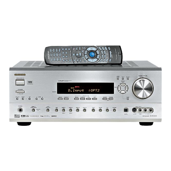
Page 4: Front Panel Facilities
TX-SR701 Front panel facilities Here is an explanation of the controls and displays on the front panel of the TX-SR701/701E/601/601E. Front panel <TX-SR701E> MASTER VOLUME AUDIO ADJUST SETUP RETURN STANDBY/ON TUNI NG PRESET POWER STANDBY LISTENING MODE REC OUT ZONE... - Page 5 Canadian models, and Australian models) FM MODE button Press to turn on and off the main power supply for the TX-SR701/ 701E/601/601E. When the TX-SR701/701E/601/601E is turned on Press to change the stereo mode from AUTO to MONO and vice with the POWER switch, the STANDBY indicator lights.
- Page 6 TX-SR701 Front panel facilities Input source buttons (DVD, VIDEO 1–4, TAPE, TUNER, CD, and PHONO (TX-SR701/701E only)) These buttons are used to select the input source. Press these buttons to select the input source for the main zone. To select the input source for the remote zone (Zone 2) or recording out (Rec Out), first press the ZONE 2 or REC OUT button, and then...
-
Page 7: Front Panel Display
TX-SR701 Front panel facilities Front panel display MUTING indicator Multi function display Flashes when the mute function is turned on. During normal operation, shows the current input source and volume. When the FM or AM input is selected, shows the frequency and preset number. -
Page 8: Rear Panel
TX-SR701 Rear panel TX-SR701/701E REMOTE When using Connecting antennas CONTROL the Zone 2 COMPONENT VIDEO LINE OUT 12V TRIGGER ZONE 2 Connecting speakers AC OUTLETS INPUT/OUTPUT terminal terminals CAUTION: SPEAKER IMPEDANCE ANTENNA FM 75 6 OHMS MIN. /SPEAKER COMPONENT VIDEO... -
Page 9: Remote Controller
SLEEP button Press to set the sleep function. The SLEEP button enables you to set the TX-SR701/701E/601/ 601E to turn off automatically after a specified time period. MACRO 1, 2 button Press to program or execute the macro function. - Page 10 1 to 9, +10, --/---, 0: For entering the number of a track. PURE A: TX-SR601/601E: Not used with the TX-SR601/601E. TX-SR701/701E: Press to select the Pure Audio mode. DIRECT, STEREO, SURR, ALL ST, DSP (TX-SR601/601E), (TX-SR701/701E), THX (TX-SR701/701E): You can select a listening mode.
-
Page 11: Supplied Accessories
TX-SR701 Supplied accessories Check that the following accessories are supplied with the TX-SR701/701E/ The following accessories may be available depending 601/601E. on the area which it was purchased. AM loop antenna × 1 FM indoor antenna × 1 Conversion plug × 1 (Use this plug if the power cord plug of the TX- SR701/701E/601/601E does not fit your AC outlet. -
Page 12: Exploded View
TX-SR701 EXPLODED VIEW P901 P101 35 U12 F903 P6931 F901 F6901 Q6050 F902 F6902 P7501 Q6060 Q6056 P7502 Q6066 F9501 T901 Except 120V and Page 12 Australian models... - Page 13 TX-SR701 BLOCK DIAGRAM - 2 HEAD PHONE MULTICHANNEL INPUT HPEN ZONE 2 (ONLY TX) (EXCEPT OF MJJ) BD3811K1 (2/2) MASTER VOLUME Power Amplifier BASS/TREBLE BOOST VLSC PREOUT MUTE +29dB SW->L BYPASS BASS/TREBLE VLSC MUTE +29dB SW->R BYPASS Z2L/SL MCSL 50KLPF...
- Page 14 TX-SR701 BLOCK DIAGRAM - 1 DIGITAL AUDIO INPUT MULT FRONT DIGITAL AUDIO OUTPUT OPTICAL +2.5V ONLY TX-SA701MJJ OPTICAL COAXIAL SRAM 1M MIN. +3.3V MEMORY CY7C1020 4ch 96/24 12.288MHZ 13.5MHZ OPTICAL 1 COAXIAL OPTICAL 2 DD/DTS/AAC CS42528 VLSC SRAM DECODER BASS-MANAGEMENT CY7C1019 SW->L...
- Page 15 TX-SR701 SCHEMATIC DIAGRAM DISPLAY-2 P7502A TO NCPS-7975 (PART-7) MODEL SA601/701 TX-SR601 TX-SR701 COUNTRY S7619 S7625 -26V AC6V AC6V S7629 NO/YES C7535 C7533 S7644 S7645 473Z 104Z S7646 5.6V S7647 R7618 R7628 NO/YES R7643 R7644 R7645 R7646 Q7582 Q7583 D7582 D7583...
- Page 16 TX-SR701 SCHEMATIC DIAGRAM DISPLAY-1 NCDIS-7960 HNA-16MM39T Q7501 P46/FIP38 P47/FIP39 FIP18 61:FIP19 P50/FIP40 FIP17 P51/FIP41 FIP16 P52/FIP42 FIP15 P53/FIP43 FIP14 P54/FIP44 FIP13 P55/FIP45 FIP12 P56/FIP46 FIP11 Q7502 P57/FIP47 FIP10 UPD78F0233GC P60/FIP48 FIP9 P61/FIP49 FIP8 P62/FIP50 FIP7 PURELED P63/FIP51 FIP6 R7535 ZONE2LED...
-
Page 17: Schematic Diagram
TX-SR701/E SCHEMATIC DIAGRAM 2-1 DSP section 000J C324 NJM4565M-D 5 R342 10 FROM FRONT P304 47/50 Q300 R334 FRONT VIDEO-4 IN P107B TO N JL7503B C330 R300 C332 392J 123J C334 47/16 R336 R338 270K PHONO 270K R339 R337 R301... - Page 18 TX-SR701/E MLS/MRS R346 R368 R374 R376 R380 10K C342 R355 1.5K DAC_L 1.2K 330J C345 SCHEMATIC DIAGRAM 2-3 122J R349 DSP section R364 R390 NJM4565M-D R321 NJM4565M-D NJM4565M-D DAC_R C340 R391 R322 R350 R356 R365 R347 122J NJM4565M-D R373 R375...
- Page 19 TX-SR701/E SCHEMATIC DIAGRAM 2-2 DSP section NADG-7952 78M12HF R9501 12 Q9501 +12VA PURE-AUDIO-SW Q101 C9509 C9507 (1W) KTC3875-GR 220/16 2SD1468-SR R9505 /2SC2712 104Z 104Z C9508 C9501 C9510 TO NAETC-7982 P105B TO TUNER PACK 220/10 +24V TO NAETC-7982 P101A C9502 220/16...
- Page 20 TX-SR701/E 1Q 6 SCHEMATIC DIAGRAM 2-4 1Q 5 DSP section 1CK 3 R181 100K 2CLR 1D 2 100K 1CLR 1 R183 Q9508 NJM2391DL1-285T R182 +2.85V +5VDSP MCLK1 R799 13.5MHZ VSS14 143 NCH-1479 NJM2933T BOOT 142 Q9510 L9501 R798 +3.3V NCH-1471...
- Page 21 TX-SR701/E SCHEMATIC DIAGRAM 3 TO NAAF-7983 TO NADG-7952 (SCH-2) (SCH-5) JL5801B P308A SEMICONDUCTORS L / R / C SL / SR / SB Q5000-04,5010-14 2SC1775A-E,F OR 2SC1845-E KTC3200-BL OR 2SC1775A-E,F OR 2SC1845-E,F C5127 Q5020-25 2SA992-E,F Q5077 10/50 R5217 Q5030-35 2SA1360-Y,O...
- Page 22 TX-SR701/E SCHEMATIC DIAGRAM 3 TO NADG-7952 NAAF-7984 Z2LPO Q5801 P308C SLPO KTC3199 Z2RPO OR 2SC1740S SRPO RL5801 *C5030~C5035 : D MODEL NONE R5163 120(1/4W) [58.0V] R5113 R5183 [57.2V] Q5033 (1/4W) C5033 R5093 [56.7V] 101K [1.1V] 100K C5053 [-0.1V] C5103 47/50...
- Page 23 TX-SR701/E SCHEMATIC DIAGRAM 4 Power amplifier section Q6030 [58.0V] R6160 R6080 R6030 Q6050 [1.1V] [1.0V] (1/4W) NAETC-7967/7973 R6140 Q6070 R6000 [0.6V] THERMAL PROT. [0.6V] 5.6K THERMAL SENS. R6381 R6380 R6070 +24V R6100 R6010 +24V 0.22 P6080 3.9K (1/4W) X2(2W) NF-FL [-0.3V]...
- Page 24 TX-SR701/E SCHEMATIC DIAGRAM 4 Power amplifier section NAAF-7966 Q6033 [58.0V] R6163 R6083 Q6053 R6033 [1.1V] (1/4W) [1.0V] Q6073 R6143 [0.6V] [0.6V] R6003 R6073 5.6K R6103 (1/4W) R6013 0.22 P6083 X2 (2W) NF-SL 3.9K NF-F C6043 Q6023 R6093 C6053 47/50 [-0.6V]...
- Page 25 TX-SR701/E SCHEMATIC DIAGRAM 5 Power supply and speaker terminal sections NAAF-7968 L6800 S1.3C SPEAKER OUT C6600 223Z R6800 22 D6600 R6810 22 ZONE2 L C6856 102J RL6600 ZONE2 R C6857 102J C6850 102J L6801 S1.3C NF-FL R6801 22 C6851 NF-FR...
- Page 26 TX-SR701/E SCHEMATIC DIAGRAM 5 Power supply and speaker terminal sections NAPS-7975 C9003 D9002 D9001 1000/35 C9001 334J D9001-9004: RL1N4003 C9004 D9003 470/35 C9002 +24V 334J D9004 -24V Q9001 +12V R9006 D9005 D9010 +5.6S C9011 NJM78M56FA C9005 D3SBA20 RL1N4003 1000/25 334J...
- Page 27 TX-SR701/E SCHEMATIC DIAGRAM 6 Video and bus line sections E201 P207B P208B NAVD-7953 C204 104Z L201 U201 OPT2 022K C205 104Z R223 U202 C245 OPT1 R224 470/6.3 C206 U203 104Z OPTOUT C203 C248 47/16 R216 P201 470/6.3 L210 022K Q211...
- Page 28 TX-SR701/E SCHEMATIC DIAGRAM 6 Video and bus line sections P2201B P2210B E2201 NAVD-7954 Q2201 RN1401 D2201 C2202 102K RL2201 P2203 P2203 RL2202 NJM4565M-D C2251 2.2/50 Q2255 Q2257 KRA102S P2203 R2275 220K NJM4565M-D C2271 104Z C2252 2.2/50 Q2255 C2201 102K P2209...
- Page 29 TX-SR701/E PRINTED CIRCUIT BOARD VIEW 7 J2909 P2201A P2210A J2924 P2202A P2212A J2910 J2918 J2908 R2909 J2907 J2956 J2946 J2954 J2916 C2903 J2952 P2001A P208A P207A J2945 NCETC-7982 25137982 J2933 J2938 J2925 J2915 Q2903 J2926 J2913 J2927 J2935 J2911 J2912...
- Page 30 TX-SR701/E WIRING VIEW P925A P926A SPEAKER Korean model only P902A NCETC- 7978 TERMINAL SOLDERING SIDE AC OUTLET TERMINAL PC BOARD PC BOARD(NAETC-7978) (NAAF-7968) JL6804B JL6803B JL6805B E921 S902 P925 P926 THERMAL PRIMARY NCETC-7967 P902 DETECTOR CIRCUIT JL6402B PC BOARD P917...
- Page 31 TX-SR701/E WIRING VIEW PREOUT. P6812 P6810 P6811 TERMINAL PC BOARD (NAAF-7983) NCAF-7983 JL5801A JL5802A MAIN -7967) CONNECTOR PC BOARD P302 P300 P301 P303 (NAETC-7982) P309 P308 CIRCUIT PC BOARD (NADG-7952) P201 DRIVER P206 P202 U203 U201 P205 P204 U202 CIRCUIT...
- Page 32 TX-SR701/E PRINTED CIRCUIT BOARD VIEW 1-2 Front panel section VIDEO1 VIDEO2 VIDEO3 S7635 S7636 S7637 PURE-AUDIO S7644 S7633 S7634 PURE-AUDIO SELECTOR D7582 AUDIO D7584 PURE-AUDIO J7507 PTY/TP DIRECT REC-OUT DISPLAY DIMMER S7642 S7643 S7645 S7646 S7647 S7632 S7631 S7621 SPK-A...
- Page 33 TX-SR701/E PRINTED CIRCUIT BOARD VIEW 1-2 Front panel section DEO3 VIDEO4 7637 S7638 S7626 S7627 S7629 S7628 TAPE TUNER P7601 TUNER TAPE PHONO VOLUME PC BOARD STEREO SURROUND MEMORY FM-MODE S7622 S7623 S7624 S7625 S7619 JL7501B NCSW-7962 25137962 S7618 ENTER...
- Page 34 TX-SR701/E PRINTED CIRCUIT BOARD VIEW 3 Q5035 C5005 R5235 R5195 J5087 R5005 R5225 C5015 J5089 R5045 R5185 C5115 J5086 R5165 Q5075 R5015 R5135 R5215 R5025 J5081 Q5065 C5095 C5045 J5084 R5105 Q5055 R5085 R5075 Q5015 R5175 J5088 R5155 R5145 J5082...
- Page 35 TX-SR701/E PRINTED CIRCUIT BOARD VIEW 2 DSP CIRCUIT PC BOARD(NADG-7952) Page 35...
- Page 36 TX-SR701/E PRINTED CIRCUIT BOARD VIEW 2-1 C390 DSP CIRCUIT PC BOARD(NADG-7952) Page 36...
- Page 37 TX-SR701/E PRINTED CIRCUIT BOARD VIEW 2-2 DSP CIRCUIT PC BOARD(NADG-7952) Page 37...
- Page 38 TX-SR701/E PRINTED CIRCUIT BOARD VIEW 2-2 R391 R379 R 377 R 377 R 77 DSP CIRCUIT PC BOARD(NADG-7952) Page 38...
- Page 39 TX-SR701/E PRINTED CIRCUIT BOARD VIEW 1-1 NCDG-7964 JL7502B P7705 HPL2 U2601 HPR2 HPDET Component side 25137961 NCETC-7961 FRONT OPTICAL INPUT PC BOARD Component side (NADG-7964) HEADPHONE TERMINAL PC BOARD(NAETC-7961) C2602 C7702 L7703 R2601 Soldering side L7701 FRONT OPTICAL INPUT PC BOARD...
- Page 40 TX-SR701/E PRINTED CIRCUIT BOARD VIEW 4 Q6015 Q6014 Q6013 Q6054 Q6053 Q6065 Q6055 Q6064 Q6063 Q6062 R6094 R6093 J6147 R6095 J6185 J6180 J6174 J6170 J6165 J6156 J6155 J6148 C6524 J6181 J6166 J6149 J6177 J6162 J6141 J6205 J6182 J6178 J6167 J6163...
- Page 41 TX-SR701/E PRINTED CIRCUIT BOARD VIEW 4 POWER AMPLIFIER PC BOARD (NAAF-7966) Q6012 Q6011 Q6010 Q6053 Q6052 Q6061 Q6051 Q6062 Q6060 Q6050 R6092 R6091 R6090 J6025 J6147 R6510 6155 J6148 J6134 J6129 J6105 J6091 J6073 J6048 J6026 J6130 J6074 J6022 J6141...
- Page 42 TX-SR701/E PRINTED CIRCUIT BOARD VIEW 5 WHITE BLACK WHITE BLACK BLUE BLACK GREEN BLACK P6803 P6802 BLACK BLACK GREY BLACK BROWN BLACK J16A J15A P6803 C6856 C6840 P6802 P6804 C6846 C6853 C6842 RL6604 C6843 RL6600 C6851 C6852 RL6603 C6857 C6845...
- Page 43 TX-SR701/E PRINTED CIRCUIT BOARD VIEW 5 D9003 C9004 25137975 E9001 JL9502B J9017 NCPS-7975 C9004 C9003 D9004 J9003 R9007 J9008 JL9501A D9001 +13VS J9013 C9002 C9001 +24V RLGND D9002 MPUGND J9007 +12V D9011 +5.6S R9001 P7502B J9005 D9010 +13VS J9002 J9001...
- Page 44 TX-SR701/E PRINTED CIRCUIT BOARD VIEW 6 Component side VIDEO CIRCUIT PC BOARD Component side (NAVD-7988) P250 2501 P250 P2211 COMPONENT VIDEO PC BOARD (NAVD-7989) Page 44...
- Page 45 TX-SR701/E PRINTED CIRCUIT BOARD VIEW 6 Soldering side R2092 R2092 VIDEO CIRCUIT PC BOARD (NAVD-7988) Soldering side R2506 R2505 R R 2519 C2511 2510 C 2512 R2518 COMPONENT VIDEO PC BOARD (NAVD-7989) Page 45...
- Page 46 TX-SR701/E IC BLOCK DIAGRAMS AND DESCRIPTIONS CS42528(192 kHz 8-Ch Codec with S/P DIF Receiver) 64 63 62 61 60 59 58 57 56 55 54 53 52 51 50 49 RXP1/GPO1 CX-SDIN1 RXP2/GPO2 CX-SCLK RXP3/GPO3 CX-LRCK RXP4/GPO4 RXP5/GPO5 DGND RXP6/GPO6...
- Page 47 TX-SR701/E IC BLOCK DIAGRAMS AND DESCRIPTIONS TC9164AF(Function switch) 74HCU04F(Hex Inverters) COM1 COM1 (TOP VIEW) Truth table COM2 COM2 TC74VHCT00AFT(2-input NAND gate) COM3 COM3 DATA SHIFT REGISTER Pin No. Symbol Function Negative power supply Ground Positive power supply 2,3,4,6,7,8,10,11 S1~S8 Input/output terminals...
- Page 48 TX-SR701/E IC BLOCK DIAGRAMS AND DESCRIPTIONS LC74763-9836(On-screen and controller) 8 BITS SERIAL LATCH PARALLEL COMMAND CONVERSION DECODER INDICATOR HORIZONTAL HORIZONTAL VERTICAL ON/OFF RAM WRITE VERTICAL SCLK CHARACTER INDICATION INDICATION INVERSION CHARACTER CONTROL ADDRESS POSITION POSITION CONTROL SIZE SIZE REGISTER REGISTER...
- Page 49 TX-SR701/E IC BLOCK DIAGRAMS AND DESCRIPTIONS LC72723M(RDS demodulator) PIN ARRANGEMENT BLOCK DIAGRAM V REF RDS-ID/READY V REF FLOUT MPXIN 15 RDCL Vdda Vddd Vdda 14 RDDA CLOCK RECOVERY Vssa LC72723 13 RST REFERENCE (57kHz) (1187.5Hz) VOLTAGE LC72723M FLOUT 12 MODE...
- Page 50 TX-SR701/E IC BLOCK DIAGRAMS AND DESCIRPIONS CS5333(24-Bit, 96 kHz Stereo A/D Converter) Interface Power Reset Master Clock MCLK Quiescent Voltage Serial Clock SCLK AINL Left Channel Analog Input Serial Data Output SDATA AINR Right Channel Analog Input Analog Power REF-GND...
- Page 51 TX-SR701/E IC BLOCK DIAGRAMS AND DESCRIPTIONS BD3812F(Audio Sound Processor) OUT1 1ch input 1ch output AGND1 OUT2 Analog ground 2ch output 2ch input Serial data select AGND2 DGND Analog ground Comparator ground MUTE (-)Power supply Mute AGND3 LOGIC Analog ground Serial data...
- Page 52 TX-SR701/E IC BLOCK DIAGRAMS AND DESCRIPTIONS BD3811K1(6ch Volume with 8ch input selector) No. Terminal Description INDSPSL DSP surround Lch input terminal INDSPC DSP center input terminal INDSPSW DSP sub woofer input terminal I N 3 1 T N F 2...
- Page 53 TX-SR701/E IC BLOCK DIAGRAMS AND DESCRIPTIONS TC9274F-020 (Analog switch) R - c h S5 S6 S7 S8 S9 S10 S11 S12 S13 S14 S15 33 32 31 30 29 28 27 26 25 24 23 S5 S6 S7 S8 S9 S10 S11 S12 S13 S14 S15...
-
Page 54: Connection Diagram
TX-SR701/E SUB-MICROPROCESSOR CONNECTION DIAGRAM Q7501 FL TUBE HNA-16MM39T D7584 PURE AUDIO IND. Q7582 D7583 ZONE 2 IND. Q7583 FIP19 P46/FIP38 40 FIP18 P47/FIP39 39 FIP17 P50/FIP40 38 FIP16 P51/FIP41 37 FIP15 P52/FIP42 36 FIP14 P53/FIP43 35 FIP13 P54/FIP44 34 FIP12... - Page 55 TX-SR701/E MAIN MICROPROCESSOR CONNECTION DIAGRAM TUNER PACK Q2253,4 Q2272,3 FRONT/CENTER/SURROUND ZONE 2 MUTE BACK/SUBWOOFER CH. RL901 PREOUT PREOUT Q 9 2 1 P O W E R R E L A Y Q9503 Q5063,4,5073,4 Q400,3 -12V Q9504 ZONE 2 OUTPUT...
-
Page 56: Connection Diagram
TX-SR701/E MAIN MICROPROCESSOR CONNECTION DIAGRAM Q205 Q201~Q203 VIDEO VIDEO CONTROL SELECTOR SWITCH SWITCH TC9164AF NJM2595M 12V TRIGGER ZONE 2 Q204 ON SCREEN DEMODULATOR LC74763 Q6701~3 ABNORMAL VOLTAGE/ CURRENT DETECTOR Y C S E P D A 1 0 0 Q7505... - Page 57 TX-SR701/E TERMINAL DESCRIPTION SUB MICROPROCESSOR Pin No. Symbol I/O Description Pin No. Symbol I/O Description Power supply terminal. Connect to 5V. Segment output terminal of P22. Ground terminal. Segment output terminal of P21. Ceramic oscillator connection terminals for main system.
- Page 58 TX-SR701/E MAIN MICROPROCESSOR TERMINAL DESCRIPTION Symbol I/O Description HPRL O Headphone relay control output pin YCSEPCLK O Not used. OSDCS O Serial communication chip select output pin for OSD IC Q204. OSDDA O Serial communication data output pin for OSD IC.
- Page 59 TX-SR701/E MAIN MICROPROCESSOR TERMINAL DESCRIPTION Symbol I/O Description DSP1BST O Boot strap output pin for first DSP IC. ~DSP1HCS O Serial communication clock output pin for Q302 and Q310. ~DSP1HACN Acknowledge input pin for first DSP IC. DSP1GP8 O PCM information output pin for first DSP IC.
- Page 60 TX-SR701/E ADJUSTMENT AND CONFIRMATION PROCEDURES 1 Idling current adjustment Before Idling adjustment, turn the trimming resistors R6040 to R6045 to counter clockwise. Connect the DC voltmeter to sockets P6080 to P6085. After turn POWER to ON, adjust the trimming resistors R6040, R6041 and R6042 so that the reading of voltmeter becomes 2.5 mV.
- Page 61 TX-SR701/E ADJUSTMENT AND CONFIRMATION PROCEDURES 2 3. Confirmation of Current detection circuit Set the unit to "Test-1-00". Connect the differentiating circuit and apply the 200Hz square signal to DVD INPUT terminal of each channel. Adjust the attenuator or Volume so that the output level becomes 35V p-p.
- Page 62 TX-SR701/E PACKING PROCEDURES Bottom Except 120V model Accessary bag Speaker Cable Put the label 81 between page 2 and page 3 of instruction manual E. Page 62...
- Page 63 REF.NO. PART NO. DESCRIPTION 27111271B Front bracket <B> 27111272B Front bracket <S> 27111273B Front bracket <G> 27212494 Front panel <B> <D/A> 27212495 Front panel <B> <D/T> 27212496 Front panel <B> <P> 27212497 Front panel <S> <P> 27212498 Front panel <G> <T/R/Q/K> 27212505 Front panel <G>...
- Page 64 801606 3SMH10W.SW+15B(CU),Special screw 830440089 4TTC+8C(BC),Self-tapping screw 27141881 Retainer <D> 838430068 3TTB+6B(BC), Self-tapping screw 801606 3SMH10W.SW+15B(CU), Special screw 29363408-1 Label, transformer 28184835 Top cover <B> 28184862 Top cover <S> 28184863 Top cover <G> 838430088 3TTB+8B(BC),Self-tapping screw <B> 838930088 3TTB+8B(UN),Self-tapping screw <G/S> 27175319B 28141494 Cushion...
- Page 65 292191 FM antenna 25056005 CV-K-1, Conversion plug <T> 25065462 YAE21-0237,Antenna adapter <T/A/K/Q/R> 29365090A Warranty card <D> 29363194 Label <D> 29363421 Label POP <D> F6901,F6902 252196 or ! 12A-UL/T-314 or F6901,F6902 252301 ! 12A-TUL-250V, Fuse <D> F6901,F6902 252100 or ! 10A-EAK or F6901,F6902 252307 ! 10A-TL250V, Fuse <O>...
- Page 66 Q6053~Q6055 2203683 * MN150S-O, Q6053~Q6055 2203684 * MN150S-Y, Q6053~Q6055 2202822 * 2SC5200-R, Q6053~Q6055 2202823 * 2SC5200-O or Q6053~Q6055 2203686 * MN150S-P,Transistor Q6060~Q6062 2202813 * 2SA1943-O or Q6060~Q6062 2202812 * 2SA1943-R,Transistor Q6063~Q6065 2203693 * MP150S-O, Q6063~Q6065 2203694 * MP150S-Y, Q6063~Q6065 2202812 * 2SA1943-R, Q6063~Q6065 2202813...
- Page 67 1A972569-1B NAETC-7969-1B,PC board for holder <O> 1A972570-1A NAETC-7970-1A,Secondary terminal PC board ass'y <D> 1A972570-1B NAETC-7970-1B,Secondary terminal PC board ass'y <O> 1A972571-1A NAETC-7971-1A,PC board for cord Clamper <D> 1A972571-1B NAETC-7971-1B,PC board for cord Clamper <O> 1A972572-1A NAETC-7972-1A, PC board for cord stopper <D> 1A972572-1B NAETC-7972-1B, PC board for cord stopper <O>...
- Page 68 1A972583-1A NAAF-7983-1A, Pre-output terminal PC board ass'y <D> 1A972583-1B NAAF-7983-1B, Pre-output terminal PC board ass'y <P> 1A972583-1D NAAF-7983-1D, Pre-output terminal PC board ass'y <T/Q> 1A972583-1E NAAF-7983-1E, Pre-output terminal PC board ass'y <R> 1A972583-1F NAAF-7983-1F, Pre-output terminal PC board ass'y <K> 1A972584-1A NAAF-7984-1A,Driver circuit PC board ass'y <D>...
- Page 69 DSP CIRCUIT PC BOARD (NADG-7952-1A/1B/1C/1D) CIRCUIT NO. PART NO. DESCRIPTION Q110,Q111 22241383R2 or NJM4565M-D or Q300 22240581R2 NJM4565M Q113,Q114 22241943R2 CS5333-KZ Q180 22241845R2 LC72723M <P> Q301 22241787R3 TC9274F-020 Q302 22241761R3 BD3811K1 Q303~Q308 22241383R2 or NJM4565M-D or 22240581R2 NJM4565M Q310 22241785R2 BD3812F Q311 222780073R2...
- Page 70 CIRCUIT NO. PART NO. DESCRIPTION Coils and Filters L131,L132 231237M022R2 or NCH-1471 or L708,L751 233533M022R2 NCH-1587-022M L180 231237K220R2 or NCH-1477 or 233533K220R2 NCH-1587-220K <P> L7001,L701 231237K220R2 or NCH-1477 or L704 233533K220R2 NCH-1587-220K L9501 231237K470R2 or NCH-1479 or 233533K470R2 NCH-1587-470K L705~L707 230958R1 BK1608LM182-T L753...
- Page 71 C9509,C9510 394542217 CE04W16V-220M(VZ),Elect. C9511 394644707 or CE04W16V-47M(VR) or 394744707 CE04W16V47M(SC),Elect. C9514,C9515 394621017 or CE04W6.3V-100M(VR) or 394721017 CE04W6.3V100M(SC),Elect. C9520,C9522 394522217 CE04W6.3V-220M(VZ) C9527 394641007 or CE04W16V-10M(VR) or 394741007 CE04W16V10M(SC),Elect. Resistors R782 43474056004R1 or RM0KJ560X04 or R787~R791 43474456004R1 RM4KJ560X4,Array R9501 442621204 RS1WBJ-12,Metal oxide R9502 441622204 RS1WBJ-22,Metal oxide...
- Page 72 CIRCUIT NO. PART NO. DESCRIPTION Coils and Filters L201~L203 231237K022R2 or NCH-1471 or L205,L208 233533K022R2 NCH-1587-022K L204,L207 231292J056R2 NCH-1572 L206 231292J056R2 NCH-1572 <O> L209 232136 NSRF-2046 L210 231237K022R2 or NCH-1471 or 233533K022R2 NCH-1587-022K Capacitors C203,C232 394644707 or CE04W16V-47M(VR) or 394744707 CE04W16V47M(SC),Elect.
- Page 73 CIRCUIT NO. PART NO. DESCRIPTION Terminals P2203 25045731 NPJ-9PDGLR519 P2209 25045333 NPJ-2PDBL185 P2211 25045696 LGY2502-0200C Sockets P2201B 25051230 NSCT-5P1020 P2210B 25051232 NSCT-7P1022 DISPLAY CIRCUIT PC BOARD (NADIS-7960-1A) CIRCUIT NO. PART NO. DESCRIPTION FL tube Q7501 212229 HNA-16MM39T Q7502 22241971R3 MPD780232GC-085-8BT Remote sensor U7501 241348...
- Page 74 CIRCUIT NO. PART NO. DESCRIPTION Sockets JL7501A 25051087 NSCT-3P874 JL7502A 25051089 NSCT-5P876 P7501A 25052345 NSCT-8P2242 P7502A 25052244 NSCT-11P2141 Plugs P7504 25056056 NPLG-8P1006 Holders Q7501A 27190989A (FL) HEADPHONE TERMINAL PC BOARD (NAETC-7961-1A) CIRCUIT NO. PART NO. DESCRIPTION Coils L7701 231237M022R2 NCH-1471 L7703,L7704 231237M022R2 NCH-1471...
- Page 75 Diodes D6000~D6005 223163, 1SS133, D6010~D6015 223205 or 1SS270A or D6306,D6307 223222 WG713A D6701,D6702 223163, 1SS133, D6906 223205 or 1SS270A or 223222 WG713A D6703,D6704 224470512 MTZJ5.1B D6707 224470512 MTZJ5.1B D6904,D6905 22380337 D10XB60H Capacitors C604~C6045 394684707 CE04W50V-47M(VR),Elect. C6050~C6055 374721034 ECQ-B50V-103J,Plastic C6230~C6235 374724734 ECQ-V50V-473J,Plastic C6701,C6706 394621017 or...
- Page 76 SPEAKER TERMINAL PC BOARD (NAETC-7968-1A/1B) CIRCUIT NO. PART NO. DESCRIPTION Diodes D6600,D6604 223163, 1SS133, D6601 223205 or 1SS270A or 223222 WG713A Coils L6800~L6805 231176S S-1.3C Capacitors C6840~C6847 374721034 ECQ-B50V-103J,Plastic C6850~C6857 374721024 ECQ-B50V-102J,Plastic Resistors RL6600,RL6601 25065563, NRL-2P5A-DC24-129, RL6603,RL6604 25065586, NRL-2P5A-DC24-142, 25065517 or NRL-2P5A-DC24-098 or 25065636 NRL-2P5A-DC24-164...
- Page 77 CIRCUIT NO. PART NO. DESCRIPTION Terminal P902 25051126 NSCT-4P913 <D> 25051125 NSCT-4P912 <P/T/Q> 25052115 NSCT-2P2013 <A> 25052664 NSCT-2P2560 <R> Sockets P931A 25051230 NSCT-5P1020 Plugs P901A 25055675 or NPLG-2P631 or 25056028 NPLG-2P0978 Label F903C 29361747 T2.5AL250V <O> CONSTANT VOLTAGE CIRCUIT PC BOARD (NAPS-7975-1A/1B/1C/1D/1E/1F) CIRCUIT NO.
- Page 78 P2210A 25055703 NPLG-7P659 PRE-OUTPUT TERMINAL PC BOARD (NAAF-7983-1A/1B/1C/1D/1E/1F) CIRCUIT NO. PART NO. DESCRIPTION Capacitors C6880~C6882 374721024 ECQ-B50V-102J,Plastic C6890~C6899 374721024 ECQ-B50V-102J,Plastic Terminals P6810 25045333 NPJ-2PDBL185 P6811 25045697 NPJ-6PWRLGGP493 P6812 25045733 NPJ-2PDNT521 Sockets JL5801A 25051096 NSCT-12P883 DRIVER CIRCUIT PC BOARD (NAAF-7984-1A/1B/1C/1D/1E/1F) CIRCUIT NO. PART NO.
- Page 79 R5180~R5185 415471004 R25J-10,NF carbon R5190~R5195 415471004 R25J-10,NF carbon Relays RL5801,RL5802 25065645 NPL-2P1A-DC4.5-169 Sockets P6000B~P6004B 25052288 NSCT-5P2185 P6005B 25052295 NSCT-12P2192 Plugs JL5801B 25055633 NPLG-12P595 P308A 25055156 NPLG-12P140 P6011B 27141859 (BUS-U) FRONT VIDEO PC BOARD (NAVD-7986-1A/1B/1C/1D/1E/1F) CIRCUIT NO. PART NO. DESCRIPTION Capacitors C2501,C2502 374724714 ECQ-B50V-471J,Plastic...
- Page 80 Sales & Product Planning Div. : 2-1, Nisshin-cho, Neyagawa-shi, OSAKA 572-8540, JAPAN Tel: 072-831-8111 Fax: 072-833-5222 ONKYO U.S.A. CORPORATION 18 Park Way, Upper Saddle River, N.J. 07458, U.S.A. Tel: 201-785-2600 Fax: 201-785-2650 E-mail: onkyo@onkyousa.com ONKYO EUROPE ELECTRONICS GmbH Liegnitzerstrasse 6, 82194 Groebenzell, GERMANY Tel: +49-8142-4401-0 Fax: +49-8142-4401-555 E-mail: info@onkyo.de...
Need help?
Do you have a question about the TX-SR701 and is the answer not in the manual?
Questions and answers