Table of Contents
Advertisement
Quick Links
OPERATION AND MAINTENANCE MANUAL FOR
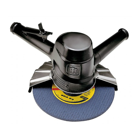
Series 99V Grinders are designed for smoothing, trimming or removing metal in foundries,
shipyards, steel mills and in construction applications.
Ingersoll–Rand is not responsible for customer modification of tools for applications on which
Ingersoll–Rand was not consulted.
IT IS THE RESPONSIBILITY OF THE EMPLOYER TO PLACE THE INFORMATION
IN THIS MANUAL INTO THE HANDS OF THE OPERATOR.
FAILURE TO OBSERVE THE FOLLOWING WARNINGS COULD RESULT IN INJURY.
PLACING TOOL IN SERVICE
•
Always operate, inspect and maintain this tool in
accordance with American National Standards
Institute Safety Code for Portable Air Tools (ANSI
B186.1).
•
For safety, top performance, and maximum durability
of parts, operate this tool at 90 psig (6.2 bar/620 kPa)
maximum air pressure at the inlet with 3/4" (19 mm)
inside diameter air supply hose.
•
Always turn off the air supply and disconnect the air
supply hose before installing, removing or adjusting
any accessory on this tool, or before performing any
maintenance on this tool.
•
Do not use damaged, frayed or deteriorated air hoses
and fittings.
•
Be sure all hoses and fittings are the correct size and
are tightly secured. See Dwg. TPD905–1 for a typical
piping arrangement.
•
Always use clean, dry air at 90 psig maximum air
pressure. Dust, corrosive fumes and/or excessive
moisture can ruin the motor of an air tool.
•
Do not lubricate tools with flammable or volatile
liquids such as kerosene, diesel or jet fuel.
•
Do not remove any labels. Replace any damaged label.
The use of other than genuine Ingersoll–Rand replacement parts may result in safety hazards, decreased tool performance, and
increased maintenance, and may invalidate all warranties.
Repairs should be made only by authorized trained personnel. Consult your nearest Ingersoll–Rand Authorized Servicenter.
Refer All Communications to the Nearest
Ingersoll–Rand Office or Distributor.
Ingersoll–Rand Company 2000
Printed in U.S.A.
SERIES 99V VERTICAL AIR GRINDERS
IMPORTANT SAFETY INFORMATION ENCLOSED.
READ THIS MANUAL BEFORE OPERATING TOOL.
03528536
USING THE TOOL
•
Always wear eye protection when operating or
performing maintenance on this tool.
•
Always wear hearing protection when operating this
tool.
•
Keep hands, loose clothing and long hair away from
rotating end of tool.
•
Anticipate and be alert for sudden changes in motion
during start up and operation of any power tool.
•
Keep body stance balanced and firm. Do not
overreach when operating this tool. High reaction
torques can occur at or below the recommended air
pressure.
•
Tool accessories may continue to rotate briefly after
throttle is released.
•
Air powered tools can vibrate in use. Vibration,
repetitive motions or uncomfortable positions may be
harmful to your hands and arms. Stop using any tool
if discomfort, tingling feeling or pain occurs. Seek
medical advice before resuming use.
•
Use accessories recommended by Ingersoll–Rand.
•
This tool is not designed for working in explosive
atmospheres.
•
This tool is not insulated against electric shock.
F
Form P6396
Edition 15
E
June, 2000
P
Advertisement
Table of Contents

Related Manuals for Ingersoll-Rand 99V60P107


Summary of Contents for Ingersoll-Rand 99V60P107
- Page 1 03528536 Form P6396 Edition 15 June, 2000 OPERATION AND MAINTENANCE MANUAL FOR SERIES 99V VERTICAL AIR GRINDERS Series 99V Grinders are designed for smoothing, trimming or removing metal in foundries, shipyards, steel mills and in construction applications. Ingersoll–Rand is not responsible for customer modification of tools for applications on which Ingersoll–Rand was not consulted.
-
Page 2: Warning Label Identification
WARNING LABEL IDENTIFICATION FAILURE TO OBSERVE THE FOLLOWING WARNINGS COULD RESULT IN INJURY. WARNING WARNING WARNING Always turn off the air sup- Always wear eye protection Always wear hearing ply and disconnect the air when operating or perform- protection when operating supply hose before install- ing maintenance on this this tool. - Page 3 COMPRESSOR (Dwg. TPD905–1) HOW TO ORDER A GRINDER VERTICAL DEPRESSED CENTER WHEEL GRINDER Model Free Speed Type 27 and 28 Wheel Spindle and Guard L. C. inches 99V60P107 6,000 5/8–11, 7” 99V60P109 6,000 5/8–11, 9” 99V77P107 7,700 5/8–11, 7” 99V85P107M 8,500 5/8–11, 7”...
- Page 4 • • Utiliser les accessoires recommandés par Ne jamais lubrifier les outils avec des liquides Ingersoll-Rand. inflammables ou volatiles tels que le kérosène, le gasol • Cet outil n’est pas conçu pour fonctionner dans des ou le carburant d’aviation.
- Page 5 SIGNIFICATION DES ETIQUETTES D’AVERTISSEMENT ATTENTION LE NON RESPECT DES AVERTISSEMENTS SUIVANTS PEUT CAUSER DES BLESSURES ATTENTION ATTENTION ATTENTION Couper toujours l’alimentation Porter toujours une Porter toujours des lunettes d’air comprimé et débrancher le protection acoustique de protection pendant flexible d’alimentation avant pendant l’utilisation de cet l’utilisation et l’entretien de d’installer, déposer ou ajuster...
-
Page 6: Mise En Service De L'outil
COMPRESSEUR D’AIR DE L’OUTIL VIDANGER RÉGULIÈREMENT (Plan TPD905–1) SPÉCIFICATIONS Modèle Vitesse à vide Meules Types 27 et 28 Arbre et protège–meule L. C. pouces 99V60P107 6.000 5/8–11, 7” 99V60P109 6.000 5/8–11, 9” 99V77P107 7.700 5/8–11, 7” 99V85P107M 8.500 5/8–11, 7”... - Page 7 MANUEL DE USO Y MANTENIMIENTO PARA AMOLADORAS NEUMATICAS VERTICALES MODELO 99V NOTA Las Amoladoras Modelo 99V están diseñadas para trabajos de pulido, recorte o eliminación de metal en fundiciones, astilleros, fábricas de acero y en la industria de construcción. Ingersoll–Rand no aceptará responsabilidad alguna por la modificación de las herramientas efectuada por el cliente para las aplicaciones que no hayan sido consultadas con Ingersoll–Rand.
-
Page 8: Etiquetas De Aviso
ETIQUETAS DE AVISO AVISO EL HACER CASO OMISO DE LOS AVISOS SIGUIENTES PODRIA OCASIONAR LESIONES. ADVERTENCIA ADVERTENCIA ADVERTENCIA Cortar siempre el suministro Use siempre protección ocular de aire y desconectar la man- Use siempre protección para cuando utilice esta herramienta guera de suministro de aire los oídos cuando utilice esta o realice operaciones de... -
Page 9: Especificaciones
ESPECIFICACIONES Modelo Velocidad Muela Tipo 27 y 28 Eje y Constante Cubremuela L. C. pulgadas 99V60P107 6.000 5/8–11, 7” 99V60P109 6.000 5/8–11, 9” 99V77P107 7.700 5/8–11, 7” 99V85P107M 8.500 5/8–11, 7”... - Page 10 MANUAL DE FUNCIONAMENTO E MANUTENÇÃ PARA RECTIFICADORES PNEUMÁTICOS VERTICAIS SÉRIE 99V AVISO Os Rectificadores Série 99V são concebidos para aplanar, aparar ou remover metal em fundições, estaleiros, aciarias e em aplicações de construção. A Ingersoll–Rand não pode ser responsabilizada pela modificação de ferramentas para aplicações para as quais não tenha sido consultada.
- Page 11 IDENTIFICAÇÃO DAS ETIQUETAS DE ADVERTÊNCIA ADVERTÊNCIA A NÃO OBEDIÊNCIA ÀS ADVERTÊNCIAS SEGUINTES PODERÁ RESULTAR EM LESÕES PESSOAIS. ADVERTÊNCIA ADVERTÊNCIA ADVERTÊNCIA Desligue sempre a alimentação Use sempre protecção Use sempre protecção para os de ar e a mangueira de auricular ao operar esta olhos ao operar ou fazer alimentação de ar antes de ferramenta.
- Page 12 PNEUMÁTICA DRENAR (Des. TPD905–1) REGULARMENTE ESPECIFICAÇÕES Velocidade Livre Mó Abrasiva Haste e Modelo Tipo 27 e 28 Protecção L. C. polegadas 99V60P107 6.000 5/8–11, 7” 99V60P109 6.000 5/8–11, 9” 99V77P107 7.700 5/8–11, 7” 99V85P107M 8.500 5/8–11, 7” Velocidade Livre Mó Abrasiva...
- Page 13 USE THIS DRAWING WITH PART LISTING FOR MODELS WITHOUT BUILT–IN OILERS (Dwg. TPA1708)
- Page 14 USE THIS PART LISTING WITH DRAWING TPA1708 FOR MODELS WITHOUT BUILT–IN OILERS PART NUMBER FOR ORDERING PART NUMBER FOR ORDERING Cylinder Case Assembly 99V60–23 ....Exhaust Deflector for models ending in –EU .
- Page 15 USE THIS DRAWING WITH PART LISTING FOR MODELS WITH BUILT–IN OILERS (Dwg. TPA717–3)
- Page 16 USE THIS PART LISTING WITH DRAWING TPA717–3 FOR MODELS WITH BUILT–IN OILERS PART NUMBER FOR ORDERING PART NUMBER FOR ORDERING ....––––– Nameplate Kit (for European Cylinder Case Assembly .
- Page 17 USE THIS PART LISTING FOR ALL MODELS PART NUMBER FOR ORDERING PART NUMBER FOR ORDERING • 33 Rotor Key ......R43F–70 Depressed Center Wheel Guard for Type 27 or 34 Rotor...
- Page 18 USE THIS PART LISTING FOR ALL MODELS PART NUMBER FOR ORDERING PART NUMBER FOR ORDERING ....99V85–186 Tune–up Kit (for models with built–in Depressed Center Wheel Nut .
- Page 19 Guards, Flanges and Spacers for 99V Grinders Guards, Flanges and Spacers for 99V Grinders Using Cup and Saucer Wheels Using Depressed Center Wheels (Dwg. TPA861–5) (Dwg. TPA862–3) Never operate the Grinder without the Wheel Retaining Screw (56 or 56A) installed in its proper place in the end of the arbor. Always securely tighten the Wheel Retaining Screw before operating the Grinder.
-
Page 20: Maintenance Section
MAINTENANCE SECTION Whenever grasping a tool or a part in a vise, always use leather–covered or copper–covered vise jaws to protect the surface of the part and help prevent distor- Always wear eye protection when operating or per- tion. This is particularly true of threaded members forming maintenance on this tool. - Page 21 MAINTENANCE SECTION 13. Set the Controller on blocks in an arbor press. Using a round piece of metal fitting the inner race of the Rear Rotor Bearing, press off the Rear Rotor Bearing Cage (45). 14. Insert the Controller into the 99V60–A952 Bearing Clamp and tighten the nut on the fixture.
- Page 22 MAINTENANCE SECTION Assembly of the Throttle and Inlet Assembly of the Motor Using an arbor press against the inner race of the bearing, install the Front Rotor Bearing (30) onto the Arbor (29). Thoroughly clean and lubricate all Throttle Valve Inspect the Front End Plate (31) for nicks or burrs.
- Page 23 MAINTENANCE SECTION 14. Center the long boss on the face of the Front End Apply a film of light grease to the inside diameter Plate (31) with the alignment mark on the face of the and outside diameter of the Rotor Bearing Seal and Cylinder Case and insert the motor into the bore align the Seal with both cylinder dowel pins.
- Page 24 MAINTENANCE SECTION TEST AND INSPECTION PROCEDURE Model Torque Speed rpm ft–lb Disconnect the Grinder from the air supply hose or 99V45 3.80 5.15 3 300 shut off air to the tool before proceeding with the test 99V60 3.50 4.75 4 400 and inspection procedure.
-
Page 25: Troubleshooting Guide
MAINTENANCE SECTION TROUBLESHOOTING GUIDE Trouble Probable Cause Solution Low power or low free speed Low air pressure at the Inlet Check the air pressure at the Inlet. The pressure must not exceed 90 psig (6.2 bar/620 kPa). Plugged Screen Clean the Screen in a clean, suitable, cleaning solution.
Need help?
Do you have a question about the 99V60P107 and is the answer not in the manual?
Questions and answers