Table of Contents
Advertisement
www.proform.com
Model No. PFEL09807.0
Serial No.
Write the serial number in the
space above for reference.
QUESTIONS?
As a manufacturer, we are commit-
ted to providing complete customer
satisfaction. If you have questions,
or if parts are damaged or missing,
DO NOT CONTACT THE STORE;
please contact Customer Care.
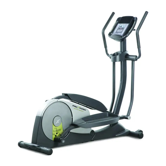
IMPORTANT: You must note the
product model number and serial
number (see the drawing above)
before contacting us:
1-888-533-1333
CALL TOLL-FREE:
Mon.–Fri. 6 a.m.–6 p.m. MT
Sat. 8 a.m.–4 p.m. MT
ON THE WEB:
www.proformservice.com
CAUTION
Read all precautions and instruc-
tions in this manual before using
this equipment. Keep this manual
for future reference.
Serial
Number
Decal
USERʼS MANUAL
Advertisement
Table of Contents

Related Manuals for Pro-Form Stride Select PFEL09807.0


Summary of Contents for Pro-Form Stride Select PFEL09807.0
- Page 1 www.proform.com USERʼS MANUAL Model No. PFEL09807.0 Serial No. Write the serial number in the space above for reference. Serial Number Decal QUESTIONS? As a manufacturer, we are commit- ted to providing complete customer satisfaction. If you have questions, or if parts are damaged or missing, DO NOT CONTACT THE STORE;...
-
Page 2: Table Of Contents
TABLE OF CONTENTS WARNING DECAL PLACEMENT ............. .2 IMPORTANT PRECAUTIONS . -
Page 3: Important Precautions
IMPORTANT PRECAUTIONS WARNING: To reduce the risk of serious injury, read all important precautions and instructions in this manual and all warnings on your elliptical exerciser before using your elliptical exerciser. ICON assumes no responsibility for personal injury or property damage sustained by or through the use of this product. -
Page 4: Before You Begin
BEFORE YOU BEGIN Thank you for selecting the revolutionary PROFORM tacting us. The model number and the location of the ® STRIDE SELECT elliptical exerciser. The STRIDE serial number decal are shown on the front cover of SELECT elliptical exerciser provides an impressive this manual. -
Page 5: Assembly
ASSEMBLY To hire an authorized service technician to assemble the elliptical exerciser, call 1-800-445-2480. Assembly requires two persons. Place all parts of the elliptical exerciser in a cleared area and remove the packing materials. Do not dispose of the packing materials until assembly is completed. In addition to the included tool(s), assembly requires a Phillips screwdriver , an adjustable wrench... - Page 6 To make assembly easier, read the information on page 5 before you begin. While another person lifts the front of the Frame (1), attach the Front Stabilizer (4) to the Frame with two M10 x 80mm Patch Screws (93) and two M10 Spring Washers (99). 2.
- Page 7 3. See the inset drawing. Hold the handle, press the latch button, and unfold the elliptical exer- ciser so that the Rear Stabilizer (3) rests on the floor. Handle Latch Button 4. Have another person hold the Water Bottle Holder (19) and the Upright (10) near the Frame (1) as shown.
- Page 8 5. Tip: Avoid pinching the Wire Harness (64). While another person slides the Water Bottle Holder (19) upward, attach the Upright (10) to the Frame (1) with four M8 x 19mm Patch Screws (86) and four M8 Split Washers (97). Avoid pinching the Wire Harness (64) 6.
-
Page 9: 24, 72), Which Are Marked With "L" And "R
7. Apply a generous amount of the included grease to the Upper Body Axle (71) and to two Wave Washers (80). Insert the Upper Body Axle (71) through the Frame (1). Place a Wave Washer (80) on each end of the Upper Body Axle. Grease Grease 8. -
Page 10: Stickers, And Orient Them As Shown
9. Identify the Left and Right Upper Body Arms (22, 23), which are marked with “L” and “R” stickers, and orient them as shown. Attach each Upper Body Arm (22, 23) with three M8 x 12mm Patch Screws (84). Orient the two Handle Covers (48) as shown. Slide the Handle Covers onto the Upper Body Arms (22, 23) so that they cover the Patch Screws (84). - Page 11 11. While another person holds the Console (11) near the Upright (10), connect the console wire to the Wire Harness (64). Insert the excess wire into the Upright. Tip: Avoid pinching the wires. Attach the Console Wire Console (11) to the Upright (10) with four M4 x 16mm Screws (78).
- Page 12 13. Apply a generous amount of grease to a Pedal Arm Axle (55). Next, tighten an M10 x 20mm Patch Screw (68) with an M10 Washer (95) into one end of the Pedal Arm Axle. Insert the Pedal Arm Axle (55) into the Right Upper Body Leg (72) as shown.
- Page 13 15. Apply a generous amount of grease to an M8 x 58mm Shoulder Bolt (104) and to the inside of the right Link Arm Bracket (45). Grease Insert the end of the right Link Arm (30) into the right Link Arm Bracket (45). Attach the right Link Arm Bracket with the M8 x 58mm Shoulder Bolt (104) and an M8 Locknut (94).
-
Page 14: How To Use The Elliptical Exerciser
HOW TO USE THE ELLIPTICAL EXERCISER HOW TO FOLD AND UNFOLD THE ELLIPTICAL HOW TO MOVE THE ELLIPTICAL EXERCISER EXERCISER To move the elliptical exerciser, first fold it as When the elliptical exerciser is not in use, the frame described at the left. Next, stand in front of the ellipti- can be folded out of the way. - Page 15 HOW TO EXERCISE ON THE ELLIPTICAL HOW TO ADJUST THE STRIDE OF THE EXERCISER ELLIPTICAL EXERCISER To mount the elliptical exerciser, hold the upper body To adjust the stride of the elliptical exerciser, first pull arms and step onto the pedal that is in the lowest one of the adjustment knobs until the adjustment arm position.
- Page 16 CONSOLE DIAGRAM FEATURES OF THE CONSOLE The console features the iFit Interactive Workout System, which enables the console to accept iFit This advanced console offers an array of features cards containing workouts designed to help you designed to make your workouts more effective and achieve specific fitness goals.
- Page 17 HOW TO USE THE MANUAL MODE The lower right display can show your Note: If there is a sheet of clear plastic on the face of pedaling pace in revo- the console, remove the plastic. lutions per minute (rpm) and the resis- 1.
- Page 18 5. Measure your heart rate if desired. 6. Turn on the fan if desired. If there are The fan has high, low, and auto speed settings; sheets of clear when you select the auto mode, the speed of the Contacts plastic on the fan will automatically increase or decrease as you metal contacts on...
- Page 19 HOW TO USE A PRESET WORKOUT During the workout, the target pacer coach will prompt you to keep your pedaling pace near the 1. Press any button on the console or begin ped- target pace setting for the current segment. When aling to turn on the console.
- Page 20 5. Begin pedaling to start the workout. HOW TO USE A HEART RATE WORKOUT 1. Press any button on the console or begin ped- Heart rate workout 1 is divided into 40 one- aling to turn on the console. minute segments. Note: For a shorter workout, stop exercising or select a different workout before When you turn on the console, the displays and the workout ends.
- Page 21 2. Insert an iFit card and select a workout. While you exercise, the target pacer coach will prompt you to maintain a constant pedaling speed. When a left indicator lights, increase your pace; To use an iFit workout, insert an iFit card into the when a right indicator lights, decrease your pace.
-
Page 22: Maintenance And Troubleshooting
MAINTENANCE AND TROUBLESHOOTING HOW TO ADJUST THE BELT Inspect and tighten all parts of the elliptical exerciser regularly. Replace any worn parts immediately. If you can feel the pedals slip while you are pedaling, To clean the elliptical exerciser, use a damp cloth and even when the resistance of the pedals is at the high- a small amount of mild soap. -
Page 23: Exercise Guidelines
EXERCISE GUIDELINES WARNING: Burning Fat—To burn fat effectively, you must exer- cise at a low intensity level for a sustained period of Before beginning time. During the first few minutes of exercise, your this or any exercise program, consult your body uses carbohydrate calories for energy. -
Page 24: Part List
PART LIST—Model No. PFEL09807.0 R0209A Key No. Qty. Description Key No. Qty. Description Frame Clamp Folding Frame Adjustment Knob Rear Stabilizer Outer Pivot Arm Bushing Front Stabilizer Link Snap Ring Pedal Bracket Pedal Arm Axle Motor Bracket Spring Upper Bushing Spindle Spacer Upper Body Arm Cap M5 Washer... - Page 25 Key No. Qty. Description Key No. Qty. Description Adjustment Pin M6 Square Nut Adjustment Spacer M4 x 45mm Screw Large Snap Ring M4 x 40mm Screw M8 x 58mm Shoulder Bolt M4 x 25mm Screw Star Washer Belt Adjustment Screw M5 x 20mm Screw –...
-
Page 26: Exploded Drawing
EXPLODED DRAWING A—Model No. PFEL09807.0 R0209A... - Page 27 EXPLODED DRAWING B—Model No. PFEL09807.0 R0209A...
-
Page 28: Ordering Replacement Parts
ORDERING REPLACEMENT PARTS To order replacement parts, please see the front cover of this manual. To help us assist you, be prepared to provide the following information when contacting us: • the model number and serial number of the product (see the front cover of this manual) •...
Need help?
Do you have a question about the Stride Select PFEL09807.0 and is the answer not in the manual?
Questions and answers
Need a battery
The type of battery needed for the Pro-Form Stride Select PFEL09807.0 is not specified in the provided context.
This answer is automatically generated